Danfoss Air Units Installation guide

Type
Installation guide
MAKING MODERN LIVING POSSIBLE
Installation Guide
Danfoss Air Units
www.heating.danfoss.com
Danfoss A/S is not liable or bound by warranty if these
instructions are not adhered to during installation or service.
The English language is used for the original instructions.
Other languages are a translation of the original instructions.
(Directive 2006/42/EC)
© 2013 Copyright Danfoss A/S
Installation Guide
Installationsvejledning
Installationshandbuch
Instrukcja obsługi
GB
.
DK
.
DE
.
PL
.
Table of Contents
1 Safety Note .............................................. 2
2 Before Start ............................................. 2
3 Installation of Air Units ...................................... 3
4 Installation of CCM Module and Air Dial ............................ 5
4.1 Electrical connections .................................... 5
4.2 Wireless connection ..................................... 5
4.3 Air Dial ............................................. 6
4.4 Mounting and removing CCM module and Air Dial .................... 6
5 Connecting to Danfoss Link™ CC ................................. 7
5.1 Connecting the Air Unit to Danfoss Link™ CC, physical installation ........... 7
5.2 Connecting the Air Unit to Danfoss Link™ CC, wireless inclusion ............ 7
5.3 Performing a network test after adding a new device .................. 8
5.4 Setting basic steps in the Danfoss Link™ CC ........................ 9
6 Balancing of the Main Air Volume ................................ 10
7 Service Menu ............................................ 11
8 Technical Specifications ...................................... 12
8.1 a² Unit ............................................. 12
8.2 a³ Unit ............................................. 14
8.3 w¹ Unit ............................................. 16
8.4 w² Unit ............................................. 18
9 Troubleshooting .......................................... 20
1 Safety Note
This appliance is not intended for use by persons (including children) with reduced physical, sensory or mental
capabilities, or lack of experience and knowledge, unless they have been given supervision or instruction con-
cerning use of the appliance by a person responsible for their safety.
Children should be supervised to ensure that they do not play with the appliance.
Apart from the replacement of air filters and exterior cleaning of the system, any kind of maintenance will re-
quire the use of trained personnel.
2 Before Start
Check the Danfoss Air Unit packing list to ensure that the shipment is complete.
If a complete Danfoss Air Solution is ordered, a packing list for the Air Flex duct system is included.
Inspect to ensure that no parts or components have been damaged.
Installation Guide Danfoss Air Units
VIEWB202 Danfoss Heating Solutions
2
Standard delivery includes:
Danfoss Air Unit
Wall bracket (if w-model)
CCM
Cabels
Optional deliveries:
Air Dial
Danfoss Link
TM
CC
3 Installation of Air Units
Attic Units a² and a³
1. Pull out the spigots
1
.
2.
Turn the spigots around and mount them using the included tapping
screws (for power drill, use lowest torque setting).
3. Make a platform
2
for the unit of 16 mm plywood or MDF sheet around
50 mm wall batts.
4.
Allow for 60 cm free space in front of unit, to assure service access.
5. Make sure that the unit is mounted absolutely horizontal.
6. A siphon
5
must always be installed with the unit (to be ordered sepa-
rately).
7.
Mount the siphon on the joist
4
below the unit or in the room below the
attic.
8.
Connect the siphon to a drain
6
.
9.
The condensate line
3
must be insulated where risk of freezing occurs.
10.
Connect the hose to the unit outlet condensate spigot. Lead the connec-
ted pipe to the outlet, allowing for a gradient of min. 1 cm/metre.
11. Remove the front panel and foam front, fill the condensate tray, check the
outlet and reassemble the front.
1
2
3
4
5
6
1
Installation Guide Danfoss Air Units
Danfoss Heating Solutions VIEWB202
3
GB
.
Wall Units w¹ and w²
1. Place the mounting bracket
1
on the wall in desired position (75 mm
from bracket bottom to unit top), mark up and drill holes. Use screws suit-
able for the wall surface (not included).
2.
Make sure that the bracket is mounted absolutely horizontal.
3. Hang the unit onto the bracket.
4. Attach the self-adhesive rubber separators
2
to the lower rear back plate.
5.
Allow for 60 cm free space in front of unit, to assure service access.
6. A siphon
3
must always be installed with the unit (to be ordered sepa-
rately).
7.
Mount the siphon on the wall below the unit.
8. Connect the siphon to the drain
5
at the unit bottom.
9.
The condensate line
4
must be insulated where risk of freezing occurs.
10.
Connect the hose to the unit outlet condensate spigot. Lead the connec-
ted pipe to the outlet, allowing for a gradient of min. 1 cm/metre.
11. Remove the front panel and foam front, fill the condensate tray, check the
outlet and reassemble the front.
75 mm
1
2
3
4
5
6
Wall Unit w¹
In order to comply with safety standards and avoid the risk of malfunction, the
supplied protection shield must be mounted on top of the w¹-unit covering the
connector plate.
Installation Guide Danfoss Air Units
VIEWB202 Danfoss Heating Solutions
4
4 Installation of CCM Module and Air Dial
4.1 Electrical connections
1. Connect power cable
4
to Air unit
3
.
2.
Plug in communication cable
2
between CCM module
1
and Air unit.
3.
Check the signal. If it is too weak, the CCM module should be placed
elsewhere, e.g. on the same floor as as the Air Dial (see Air Dial Link
Test).
4. If possible, place the CCM module close to an ethernet connection for
future connection to PC.
5. If accessories (electrical preheating, electrical afterheating, water heat-
ing surface or geothermal surface) are present, the pin on terminals 5
and 6 must be removed (also see the instructions included with the ac-
cessories).
1
2
3
4
5
6
1
2
3
4
Communication cable connections:
1. White/Orange, 2. Orange, 3. Black, 4. White/Blue, 5. Blue, 6. Black
Note! The communication cable can be extended up to 200 m. Use shielded cable , 22 or 24 AWG with 2 x twisted
pair.
4.2 Wireless connection
When powering up the CCM module a green LED will flash slowly, indicating
the CCM module has yet to be connected to the Air Dial.
To connect the Air Dial, insert the batteries. The Air Dial starts in installation
mode and automatically guides through the set-up.
1.
Set language.
2. Create network (press button on CCM module and then press Air Dial).
3. Set basic step (setting up the main air volume).
4. Finish.
Green LED lights continuously Connected established
Red LED flashes slowly 5 times Connection attempt failed, see Troubleshooting.
Tab. 2: LED blink patterns on the CCM
Installation Guide Danfoss Air Units
Danfoss Heating Solutions VIEWB202
5
GB
.
4.3 Air Dial
The Air Dial has an integrated temperature sensor. To ensure best possi-
ble performance, place the Air Dial according to following guidelines:
Place the Air Dial 80-150 cm above floor level.
Place the Air Dial free of curtains etc.
Place the Air Dial where the temperature is repre-
sentative.
!
Do not place the Air Dial in bathrooms.
Do not place the Air Dial in direct sunlight.
Do not place the Air Dial onto outer wall.
Do not place the Air Dial directly above heat
source.
Air Dial Link Test
Before mounting the Air Dial permanently, perform a link test to ensure that transmission conditions are suffi-
cient for the required location:
1.
Press the Air Dial button for 5 seconds to access the Service Menu (The Service Menu remains visible for
one hour).
2. Select the Link Test function.
3. The function shows if the transmission conditions are sufficient or not.
4. If the link test fails, see Troubleshooting.
4.4 Mounting and removing CCM module and Air Dial
CCM module
Mounting:
1.
Place the CCM on the
wall bracket.
2. Press downwards to
click the CCM into
place.
2
1
Removing:
1.
Press in the two latch-
es on the side.
2. Pull the CCM upwards.
Air Dial
Mounting:
1.
Place the Air Dial on
the wall bracket.
2. Press downwards to
click the Air Dial into
place.
1
2
Removing:
1.
Lift the Air Dial.
2. Pull the Air Dial away.
1
2
Installation Guide Danfoss Air Units
VIEWB202 Danfoss Heating Solutions
6
5 Connecting to Danfoss Link™ CC
5.1 Connecting the Air Unit to Danfoss Link™ CC, physical installation
1. Connect power cable
4
to Air unit
3
.
2.
Plug in communication cable
2
between CCM module
1
and Air unit.
3.
If possible, place the CCM module close to an ethernet connection for
future connection to PC.
4. If accessories (electrical preheating, electrical afterheating, water heat-
ing surface or geothermal surface) are present, the pin on terminals 5
and 6 must be removed (also see the instructions included with the ac-
cessories).
5. The Air Unit is now ready to be added to the Danfoss Link™ CC.
1
2
3
4
5
6
1
2
3
4
Communication cable connections:
1. White/Orange, 2. Orange, 3. Black, 4. White/Blue, 5. Blue, 6. Black
Note! The communication cable can be extended up to 200 m. Use shielded cable , 22 or 24 AWG with 2 x twisted
pair.
5.2 Connecting the Air Unit to Danfoss Link™ CC, wireless inclusion
Remove the front cover of the Danfoss Link™ CC by gently pulling it
off, pull near the edges of the cover.
Press the SETUP pin for 3 seconds to enter the service area.
Note!
The Air Unit must be added to the network as a service device. For further instructions on the network inclu-
sion, see the installation guide supplied with the Danfoss Link™ CC.
Add any dedicated repeater units (CF-RU) BEFORE adding the Air Unit to the wireless network.
Installation Guide Danfoss Air Units
Danfoss Heating Solutions VIEWB202
7
GB
.
?
1
Ser
vice Options
Rooms and Devices
es
?
2
Rooms and Devices
Add Service Devices
ices
?
3
Add Service Device
Begin Registration
ion
Click here on the CCM for adding
the Air Unit
Note! During installation, the distance between the Danfoss Link™ CC and the CCM must not exceed 1.5m.
Green LED flashes slowly CCM module has not yet been connected to the Danfoss Link™ CC
Green LED lights continuously CCM module is now connected to the Danfoss Link™ CC
Red LED flashes slowly 5 times Connection attempt failed
Tab. 2: LED blink patterns on the CCM
5.3 Performing a network test after adding a new device
After finishing installation, perform a network test, to ensure that communication between added devices and
the Danfoss Link™ CC is stable.
Note! Do not perform the network test before the Danfoss Link™ CC is mounted in its final position.
?
1
S
ervice Options
Status and Diagnostics
tics
?
2
Status and Diagnostics
Network
?
3
Wireless Network Status
Start Network Test
est
At the end of the network test the Danfoss Link™ CC awaits for all battery operated devices to wake up and
report. Follow the instructions given on the screen. If the network test is running smoothly, there will be no
need for further interaction. If the network test is performing slow, the Danfoss Link™ CC guides through trou-
bleshooting and gives usefull tips for speeding up the process.
Installation Guide Danfoss Air Units
VIEWB202 Danfoss Heating Solutions
8
5.4 Setting basic steps in the Danfoss Link™ CC
Now the Air Unit has been added to the wireless system, and is ready for balancing of the air flow. If the Air Unit
has just been added to the system, the screen will prompt for setting the basic extract and supply air step.
If the system was started earlier/by others, enter the basic settings through the Service Menu by pressing the
Air Dial button for 5 seconds. Go through the following steps.
?
1
Ser
vice Options
Rooms and Devices
es
?
2
Rooms and Devices
Manage Devices
es
?
3
Manage Devices
Congure device
?
4
S
elect Device
Air unit
?
5
Congure Device
System settings
?
6
S
ystem settings
Set basic steps
Installation Guide Danfoss Air Units
Danfoss Heating Solutions VIEWB202
9
GB
.
6 Balancing of the Main Air Volume
To achieve the best possible performance, it is vital to balance the main air
volumes (balancing will also help protecting the house against fungus and
dry rot). The system should not be balanced/commisioned at outdoor tem-
peratures below -3°C, as the system will go into frost protection mode (indica-
ted by a flashing icon on the display. If necessary to perform balancing at out-
door air temperatures below -3°C, remove power for 20 seconds to de-acti-
vate frost protection for 90 minutes.
Note! Close all doors and turn off the cooker hood.
1.
Remove the front panel from unit by pulling the handles.
2. See the drawing of the duct system, where suggested pre-setting values
for all air valves are stated. Close the valves completely, and turn them
full turns towards open (number of turns as indicated on the duct sys-
tem drawing). When setting up the systems for which Danfoss has not
dimensioned the duct system, set the supply and extract valves in ac-
cordance with the instructions of the project manager.
3. If dampers are included in the system, open these completely.
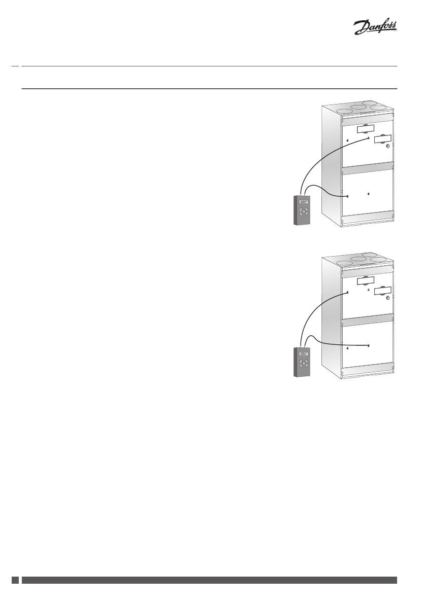
4. Mount measuring tubes between the unit’s measuring points on the ex-
tract side and differential pressure gauge.
5. Find the required flow on the system diagram (sticker on front cover)
with the corresponding differential pressure value. If the pressure is too
low, adjust the fan step upwards until you reach the required pressure.
6. Move the measuring tubes to the measuring points on the supply side
and use the same procedure to set the supply air.
7. After the main air volumes have been adjusted, the set-up of individual
valves needs to be carried out. In most cases, this will entail minor
changes to the chosen basic steps, but this can be done in the room by
adjusting the valves, or by using the Air Dial to fine tune basic steps.
Measuring the extract
Measuring the supply
Adjusting an operational system
1.
Press Air Dial for 5 seconds to get access to the Service menu.
2. Press ”set basic step” to activate the special commissioning mode
(where all outside influences are blocked - the installer controls the ex-
tract and supply air fans completely with 1-100% fan speed). The Service
menu remains visible for one hour and then disappears.
Installation Guide Danfoss Air Units
VIEWB202 Danfoss Heating Solutions
10
7 Service Menu
Press Air Dial for 5 seconds to access the Service Menu to change basic set-
tings like language, filter timer, basic steps etc.
System Reset
1.
If the system has already been balanced, make a note of the basic fan
steps for later use. The values are found in the Service Menu: Service >
Info > Basic Steps.
2. Remove and re-insert the Air Dial batteries while pressing the button
until a beep is heard. The Air Dial is now in start-up mode.
3. Remove the supply or communication cable.
4. While re-connecting the cable, press the CCM module button until only
the green LED is flashing.
5. The system is now reset to factory settings.
Service
Back
Info
Set filter timer
Set language
Set basic step
Link test
Accessories
Installation Guide Danfoss Air Units
Danfoss Heating Solutions VIEWB202
11
GB
.
8 Technical Specifications
8.1 a² Unit
Dimensions
450
325
177
160
1263
1180
600
1
2
3
4
580
450
325
177
1
Outdoor air
2
Exhaust air
3
Extract air
4
Supply air
Weight of unit: 52 kg
Front view (without front panel)
1
2
3
4
5
6
6
5
1
Filter, extract air
2
Filter, supply air
3
Flow chart (for balancing)
4
Filter reset button
5
Differential pressure for extract air
6
Differential pressure for supply air
Capacity Temperature ratio
Pressure [Pa] η [%]
100%
85%
1000 J/m³
70%
58%
46%
33%
21%
350
300
250
200
150
100
50
0
0 50 100 150 200 250 300 350 400 450
*0.45 W/m³/h
Flow [m³/h]
83%
84%
85%
86%
87%
88%
89%
90%
91%
92%
93%
94%
0
50 100 150 200 250 300
Flow [m³/h]
* 0.45 W/m³/h = "Passiv Haus" requirements.
Flow [m³/h] Pext. [Pa] SFP [J/m³] P
1
tot. [W]
160 50 615 27
220 70 728 44
220 100 854 52
260 70 783 57
260 100 894 65
300 90 936 78
Tab. 3: Capacity for the a² unit
Extract air Fresh air
t = 21 °C RH = 36% t = -3 °C RH = 80% with condensation and 5% imbalance
t = 25 °C RH < 27% t = 5 °C as acc. to EN308
Tab. 4: Temperature ratio for the a² unit
Installation Guide Danfoss Air Units
VIEWB202 Danfoss Heating Solutions
12
Flow
m³/h
Pres-
sure
Pa
Meas-
ured at
Frequency band [Hz], sound power Lw (A) [dB(A)] Sound pres-
sure Lp(A)
(standard*
room) [dB(A)]
63 125 250 500 1000 2000 4000 8000
162 70
Supply
air duct
23 34 40 36 29 25 17 18
Extract
air duct
23 33 39 37 29 24 18 18
Cabinet 40
162 100
Supply
air duct
25 35 43 38 31 28 18 18
Extract
air duct
25 36 42 39 30 25 17 18
Cabinet 41
216 70
Supply
air duct
26 36 44 39 33 30 19 18
Extract
air duct
28 36 43 41 34 29 18 18
Cabinet 45
216 100
Supply
air duct
26 37 44 40 34 31 19 18
Extract
air duct
27 37 45 42 35 30 19 18
Cabinet 46
250 100
Supply
air duct
28 39 46 42 37 33 21 18
Extract
air duct
30 39 48 45 38 33 20 18
Cabinet 49
* Values for sound pressure calculated for a standard room with A = 10 m², H = 2.4m and mean absorption 0.2.
Tab. 5: Sound data for the a² unit
Installation Guide Danfoss Air Units
Danfoss Heating Solutions VIEWB202
13
GB
.
8.2 a³ Unit
Dimensions
250
440
160
528
318
1180
1342
600
1
2
3
4
780
440
160
528
318
1
Outdoor air
2
Exhaust air
3
Extract air
4
Supply air
Weight of unit: 67 kg
Front view (without front panel)
1
2
3
4
5
6
6
5
1
Filter, extract air
2
Filter, supply air
3
Flow chart (for balancing)
4
Filter reset button
5
Differential pressure for extract air
6
Differential pressure for supply air
Capacity Temperature ratio
Pressure [Pa] η [%]
40%
56%
82%
100%
1000 J/m³
300
250
200
150
100
50
0
0
50 100 150 200 250 300 350 400 450 500 550 600
*0.45 W/m³/h
Flow [m³/h]
80%
81%
82%
83%
84%
85%
86%
87%
88%
89%
90%
0
50 100 150 200 250 300 350
400 450 500
Flow [m³/h]
* 0.45 W/m³/h = "Passiv Haus" requirements.
Flow [m³/h] Pext. [Pa] SFP [J/m³] P
1
tot. [W]
200 70 787 44
350 70 835 81
450 70 973 122
350 100 1000 97
Tab. 6: Capacity for the a³ unit
Extract air Fresh air
t = 21 °C RH = 36% t = -3 °C RH = 80% with condensation and 5% imbalance
t = 25 °C RH < 27% t = 5 °C as acc. to EN308
Tab. 7: Temperature ratio for the a³ unit
Installation Guide Danfoss Air Units
VIEWB202 Danfoss Heating Solutions
14
Flow
m³/h
Pres-
sure
Pa
Meas-
ured at
Frequency band [Hz], sound power Lw (A) [dB(A)] Sound pres-
sure Lp(A)
(standard*
room) [dB(A)]
63 125 250 500 1000 2000 4000 8000
350 70
Supply
air duct
35 45 56 49 47 44 31 16
Extract
air duct
35 44 54 48 48 44 31 19
Cabinet 57
450 100
Supply
air duct
39 48 62 55 52 50 37 22
Extract
air duct
39 47 61 55 53 48 37 20
Cabinet 61
* Values for sound pressure calculated for a standard room with A = 10 m², H = 2.4m and mean absorption 0.2.
Tab. 8: Sound data for the a³ unit
Installation Guide Danfoss Air Units
Danfoss Heating Solutions VIEWB202
15
GB
.
8.3 w¹ Unit
530
1005
108
287
438
125
161
254
296
125
430
224
160
1
2
3
4
5
6
7
89
98
10
1
Supply air
2
Extract air
3
Exhaust air
4
Outdoor air
5
Condensate drain
6
Filter, extract air
7
Filter, supply air
8
Differential pressure for ex-
tract air
9
Differential pressure for sup-
ply air
10
Filter reset button
Weight of unit: 32 kg
Capacity Temperature ratio
Pressure [Pa] η [%]
85%
70%
58%
46%
33%
21%
*0.45 W/m³/h
1000 J/m³
350
300
250
200
150
100
50
0
0 50 100 150 200 250 300
100%
Flow [m³/h]
84%
85%
86%
87%
88%
89%
90%
91%
92%
93%
0 50 100 150 200 250
Flow [m³/h]
* 0.45 W/m³/h = "Passiv Haus" requirements.
Flow [m³/h] Pext. [Pa] SFP [J/m³] P
1
tot. [W]
100 35 588 16
100 55 682 19
140 60 710 28
140 70 759 30
180 70 798 40
180 100 945 47
Tab. 9: Capacity for the w¹ unit
Extract air Fresh air
t = 21 °C RH = 52% t = 5 °C RH = 80% with condensation and 5% imbalance
t = 25 °C RH < 27% t = 5 °C as acc. to EN308
Tab. 10: Temperature ratio for the w¹ unit
Installation Guide Danfoss Air Units
VIEWB202 Danfoss Heating Solutions
16
Flow
m³/h
Pres-
sure
Pa
Meas-
ured at
Frequency band [Hz], sound power Lw (A) [dB(A)] Sound pres-
sure Lp(A)
(standard*
room) [dB(A)]
63 125 250 500 1000 2000 4000 8000
126 70
Supply
air duct
20 30 41 42 38 30 19 18
Extract
air duct
18 30 41 41 30 26 18 18
Cabinet 47
126 100
Supply
air duct
22 32 46 45 39 32 21 18
Extract
air duct
22 33 43 42 32 27 19 18
Cabinet 50
162 70
Supply
air duct
23 31 43 46 41 33 22 18
Extract
air duct
26 31 42 43 33 29 21 18
Cabinet 53
162 100
Supply
air duct
28 33 44 48 43 35 23 18
Extract
air duct
29 34 44 51 37 31 23 18
Cabinet 55
216 70
Supply
air duct
28 33 44 54 46 37 28 18
Extract
air duct
27 33 43 52 39 33 27 18
Cabinet 57
216 100
Supply
air duct
28 35 45 55 46 38 29 18
Extract
air duct
32 34 44 52 40 34 28 18
Cabinet 56
* Values for sound pressure calculated for a standard room with A = 10 m², H = 2.4m and mean absorption 0.2.
Tab. 11: Sound data for the w¹ unit
Installation Guide Danfoss Air Units
Danfoss Heating Solutions VIEWB202
17
GB
.
8.4 w² Unit
590
1055
580
126
270
389
110
295
480
1
2
3
4
5
6
7
8
9
98
10
1
Supply air
2
Extract air
3
Exhaust air
4
Outdoor air
5
Condensate drain
6
Filter, extract air
7
Filter, supply air
8
Differential pressure for ex-
tract air
9
Differential pressure for sup-
ply air
10
Filter reset button
Weight of unit: 45 kg
Capacity Temperature ratio
Pressure [Pa] η [%]
100%
85%
70%
58%
46%
33%
21%
300
250
200
150
100
50
0
*0.45 W/m³/h
1000 J/m³
0 50 100 150 200 250 300 350 400
Flow [m³/h]
83%
84%
85%
86%
87%
88%
89%
90%
91%
92%
93%
94%
0
50 100 150 200 250 300
Flow [m³/h]
* 0.45 W/m³/h = "Passiv Haus" requirements.
Flow [m³/h] Pext. [Pa] SFP [J/m³] P
1
tot. [W]
160 50 700 31
220 70 832 51
220 100 963 59
260 70 892 64
260 100 996 72
280 90 1000 78
Tab. 12: Capacity for the w² unit
Extract air Fresh air
t = 21 °C RH = 36% t = -3 °C RH = 80% with condensation and 5% imbalance
t = 25 °C RH < 27% t = 5 °C as acc. to EN308
Tab. 13: Temperature ratio for the w² unit
Installation Guide Danfoss Air Units
VIEWB202 Danfoss Heating Solutions
18
  • Page 1 1
  • Page 2 2
  • Page 3 3
  • Page 4 4
  • Page 5 5
  • Page 6 6
  • Page 7 7
  • Page 8 8
  • Page 9 9
  • Page 10 10
  • Page 11 11
  • Page 12 12
  • Page 13 13
  • Page 14 14
  • Page 15 15
  • Page 16 16
  • Page 17 17
  • Page 18 18
  • Page 19 19
  • Page 20 20
  • Page 21 21
  • Page 22 22
  • Page 23 23
  • Page 24 24
  • Page 25 25
  • Page 26 26
  • Page 27 27
  • Page 28 28
  • Page 29 29
  • Page 30 30
  • Page 31 31
  • Page 32 32
  • Page 33 33
  • Page 34 34
  • Page 35 35
  • Page 36 36
  • Page 37 37
  • Page 38 38
  • Page 39 39
  • Page 40 40
  • Page 41 41
  • Page 42 42
  • Page 43 43
  • Page 44 44
  • Page 45 45
  • Page 46 46
  • Page 47 47
  • Page 48 48
  • Page 49 49
  • Page 50 50
  • Page 51 51
  • Page 52 52
  • Page 53 53
  • Page 54 54
  • Page 55 55
  • Page 56 56
  • Page 57 57
  • Page 58 58
  • Page 59 59
  • Page 60 60
  • Page 61 61
  • Page 62 62
  • Page 63 63
  • Page 64 64
  • Page 65 65
  • Page 66 66
  • Page 67 67
  • Page 68 68
  • Page 69 69
  • Page 70 70
  • Page 71 71
  • Page 72 72
  • Page 73 73
  • Page 74 74
  • Page 75 75
  • Page 76 76
  • Page 77 77
  • Page 78 78
  • Page 79 79
  • Page 80 80
  • Page 81 81
  • Page 82 82
  • Page 83 83
  • Page 84 84
  • Page 85 85
  • Page 86 86
  • Page 87 87
  • Page 88 88
  • Page 89 89
  • Page 90 90
  • Page 91 91
  • Page 92 92

Danfoss Air Units Installation guide

Type
Installation guide

Ask a question and I''ll find the answer in the document

Finding information in a document is now easier with AI