Page is loading ...

© Copyright 2016, Capital Safety
FORM NO: 5903352
REV: F
USER INSTRUCTION MANUAL
The Ultimate in Fall Protection
ADVANCED
Davit with Guardrail Cage
Model Number: 8530352
1
8530352

2
2
C
C
A
B

3
3 4
A≤10°
H ≤ 2’
(0.62 m)
A
5 6
A. B. C. D.
E. F. G.
ABC

4
7
1 2
3 4
5 6

5
8

6
9
1
2
3

7
10
Legend
Work Positiong
Fall Arrest

8
WARNING: This product is part of a Personal Fall Arrest and Work Positioning system. The user must follow the manufacturer’s instructions
for each component of the system. These instructions must be provided to the user of this equipment. The user must read and understand
these instructions before using this equipment. Manufacturer’s instructions must be followed for proper use and maintenance of this equipment.
Alterations or misuse of this product or failure to follow instructions may result in serious injury or death.
IMPORTANT: If you have questions on the use, care, or suitability of this equipment for your application, contact Capital Safety. For general
questions, refer to national Standards including the ANSI Z359 (.0, .1, .2, .3, and .4) family of standards on fall protection, ANSI A10.32, and
applicable local, state, and federal (OSHA) requirements governing occupational safety for more information about fall protection systems.
IMPORTANT: Prior to installation and use of this equipment, record the product identifi cation information from the ID label in the
Inspection and Maintenance Log (Table 2) at the back of this manual.
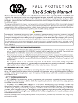
PRODUCT DESCRIPTION:
Figure 1 illustrates the Advanced
®
Davit with Guardrail Cage. The Davit with Guardrail Cage is a folding Guardrail Cage (A) with
an integrated Davit Base (B) for inserting an Advanced One-Piece Davit Mast (C). See Table 1 for Parts and Specifi cations.
1
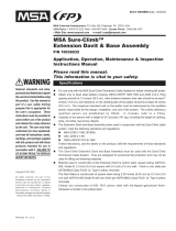
Table 1 – Parts and Specifi cations
Component Specifi cations:
Figure 2
Reference Component Materials
A
Guardrail Cage Guard Rail Sections - Powder Coated Aluminum Tubing
Legs - Powder Coated Aluminum Tubing
Strap - Polyester Webbing
B
Davit Base
(Rated for use with
8548276 Davit only.)
Sleeve - Powder Coated Aluminum Tubing
Plates - Powder Coated Aluminum
Disc - Plastic
C
One-Piece Davit Mast Mast - Powder Coated Aluminum Tubing
Mast Head Receiver - Powder Coated Aluminum Tubing
Head Tube - Zinc Plated Steel Tubing
Head Plates -Zinc Plated Steel
Gusset Plates - Powder Coated Aluminum
Gusset Adjustement Tubes - Annodized Aluminum Tube and Steel Rod
Mounting Bracket - Powder Coated Aluminum
Adapter Bracket - Steel
U-Bracket (Fall Arrest Anchorage Point on the Upright Mast) - Stainless
Steel, rated for up to 5,000 lb (22.2 kN) Vertical () Load
System Specifi cations:
Capacity
(Personnel):
1 Person ≤ 450 lbs (204 kg) - The Davit is designed for one user with a combined weight (clothing, tools,
etc.) of no more than 450 lbs (204 kg) at a minimum 2:1 Safety Factor.
For Rescue, a 5:1 safety factor is maintained up to a maximum weight of 310 lbs (141 kg) per ANSI Z359.4.
Structure: 5,000 lb (22.2 kN) - Structure on which the Davit with Guardrail Cage rests must be certifi ed by a Qualifi ed
Person
1
as capable of supporting a 5,000 lb (22.2 kN) load.
Anchorage
Points:
Each Anchorage Point on the system has been tested and verifi ed with a Safety Factor of 2:1 (1,800 lbs) per
OSHA 1926.502 (d)(15) & (d)(15)(i):
A4
A3
A2
A1
*Max.
15”
A1
A1
5,000 lbs*
(22 kN)
ANSI Z359.1
OSHA 1926.502
A2
1,800 lbs
(8 kN)
OSHA 1926.502
A3
1,800 lbs
(8 kN)
OSHA 1926.502
A4
1,800 lbs
(8 kN)
OSHA 1926.502
* 5,000 lbs (22 kN) @ ≤ 15” (38 cm)
1 Qualifi ed Person: A person with a recognized degree or professional certifi cate and with extensive knowledge, training, and experience in the Fall Protection and
Rescue fi eld who is capable of designing, analyzing, evaluating, and specifying Fall Protection and Rescue systems to the extent required by the standard(s).

9
Table 1 – Parts and Specifi cations
Parts Diagram:
Parts List:
Item Qty Part No. Description Item Qty Part No. Description
1 1 8510518 FOOT,SWIVEL,3 1/2" RUBBER 19 1 8515570 LABEL,WARNING,INSTRUCT
2 2 8511512 FOOT PAD ASSEMBLY 20 2 8542019 SPACER,SS,.390X.500X3.020
3 1 8548276 DAVIT ARM ASSEMBLY 21 2 8542021 SPACER,STEEL,.516X.675X2.531,ZP
4 1 8542023 WELDMENT,BASE,BASIC HOIST W/CAGE 22 2 9500826 WASHER,FLAT,3/8,N,ZP
5 1 8542027 WELDMENT,GATE,BASIC HOIST W/CAGE 23 1 9500983 BOLT,HH,3/8-16X1 1/4,ZP,GR8
6 1 8542028 WELDMENT,LEFT SECTION,BASIC HOIST W/CAGE 24 6 9501720 SCREW,HSH,1/4-20X4,ZP
7 1 8542029 WELDMENT,RIGHT LEG,BASIC HOIST W/CAGE 25 2 9501831 NUT,HEX,LOCK,1/2-13,ZP
8 1 8542030 WELDMENT,LEFT LEG,BASIC HOIST W/CAGE 26 2 9503645 WASHER,FLAT,3/8,W,ZP
9 1 8542035 STRAP,8530352 27 4 9503821 NUT,HEX,LOCK,1/4-20,ZP
10 1 8543465 PIN & CABLE ASSY,3/8 X 1.75,LOCK,X8" 28 1 9504040 RIVET, BLIND,3/16x1/2,ZP
11 2 8547656 PIN & CABLE ASSY,8530352 29 1 9504547 LABEL,ID,ADVANCE SYS,MADE IN USA
12 1 5903352 INSTRUCT,BASIC HOIST WITH CAGE 30 1 9505716 NUT,HEX,LOCK,3/8-16,ZP
13 4 8510037 WASHER,FLAT,1/2,N,ZP 31 1 9510992 LOCKTITE,380,BLACK
14 1 8510074 DISC,SLIDE,SLEEVE,UCL 32 1 9510993 SCREW,SET,1/4-28X1/2,HALF DOG,ZP
15 1 8510075 LINER,PVC,SLEEVE,UCL 33 1 9512131 1"-10 DBLE START x 6, ALUM SCREW LEG
16 2 9512389 BOLT,HH,3/8-16X4 1/4,ZP,GR8 34 1 9512142 HANDLE,PLASTIC,4"OD
17 1 8512041 RRING,EXT,1,ZP 35 1 9512143 PIN,SPRING,3/8X3.75,ZP
18 2 8512454 BOLT,HH,1/2-13X3 3/4,ZP,GR8 36 1 9512148 FOOT,LEVELING,1/2-13X3 THREAD,1.5"DIA FOOT

10
1.0 PRODUCT APPLICATION
1.1 PURPOSE: Advanced
™
Anchorage Systems are designed to provide anchorage connection points for a Personal Fall Arrest
System (PFAS).
WARNING: Unless otherwise noted, Capital Safety equipment is designed for use with Capital Safety approved components and
subsystems only. Substitution or replacement with non-approved components or subsystems may jeopardize compatibility of equipment
and may affect safety and reliability of the complete system. Do not hang, lift, or support tools or equipment from the Anchorage
System, or attach guy lines for antennas, phone lines, etc.
1.2 SUPERVISION: Installation of this equipment must be supervised by a Qualifi ed Person
1
. Use of this equipment must be
supervised by a Competent Person
4
.
1.3 TRAINING: This equipment must be installed and used by persons trained in its correct application. This manual is to be
used as part of an employee training program as required by OSHA. It is the responsibility of the users and installers of
this equipment to ensure they are familiar with these instructions, trained in the correct care and use of this equipment,
and are aware of the operating characteristics, application limitations, and consequences of improper use of this
equipment.
IMPORTANT: Training must be conducted without exposing the user to a fall hazard. Training should be repeated periodically.
1.4 RESCUE PLAN: When using this equipment and connecting subsystem(s), the employer must have a rescue plan and
the means at hand to implement and communicate that plan to users, authorized persons
2
, and rescuers
3
. A trained, on-
site rescue team is recommended. Team members should be provided with the equipment and techniques to perform a
successful rescue. Training should be provided on a periodic basis to ensure rescuer profi ciency.
1.5 INSPECTION FREQUENCY:
The Advanced
Davit with Guardrail Cage
shall be inspected by the user before each use and,
additionally, by a competent person
4
other than the user at intervals of no more than one year
5
. Inspection procedures
are described in the “Inspection and Maintenance Log” (Table 2). Results of each Competent Person inspection should be
recorded on copies of the “Inspection and Maintenance Log”.
1.6 AFTER A FALL: If the Advanced Davit with Guardrail Cage is subjected to the forces of arresting a fall, it must be
removed from the fi eld of service immediately and replaced or inspected by an Authorized Capital Safety Representative.
2.0 SYSTEM CONSIDERATIONS
2.1 ANCHORAGE: Structure on which the Advanced Davit with Guardrail Cage is placed or mounted must meet the
Anchorage specifi cations defi ned in Table 1.
FROM OSHA: Anchorages used for attachment of Personal Fall Arrest Systems shall be independent of any anchorage being used
to support or suspend platforms, and capable of supporting at least 5,000 lbs (22 kN) per user attached, or be designed, installed, and
used as part of a complete Personal Fall Arrest System which maintains a safety factor of a least 2, and is under the supervision of a
qualifi ed person.
2.2 PERSONAL FALL ARREST SYSTEM: Figure 1 illustrates typical Fall Arrest applications of the Advanced Davit with
Guardrail Cage. Personal Fall Arrest Systems (PFAS) used with the system must meet applicable OSHA, ANSI, state, and
federal requirements. The PFAS shall incorporate a Full Body Harness and meet the following capabilities:
Maximum Arresting Force Maximum Free Fall Distance
PFAS with Shock Absorbing Lanyard 900 lb (4 kN) 6 ft (1.8 m)
Arresting Force Maximum Free Fall Distance
PFAS with Self Retracting Device 900 lb (4 kN) Maximum Arresting Force
or 900 lb (4 kN) Average Arresting
Force (as defi ned in ANSI Z359.14)
2 ft (0.61 m)
IMPORTANT: Under NO circumstances is a PFAS with a Free Fall distance greater than 6 ft (1.8 m) acceptable for use with the
Advanced Anchorage System.
2.3 FALL PATH AND SRL LOCKING SPEED: A clear path is required to assure positive locking of an SRL. Situations which
do not allow for an unobstructed fall path should be avoided. Working in confined or cramped spaces may not allow the
body to reach sufficient speed to cause the SRL to lock if a fall occurs. Working on slowly shifting material, such as sand
or grain, may not allow enough speed buildup to cause the SRL to lock.
2.4 HAZARDS: Use of this equipment in areas with environmental hazards may require additional precautions to prevent
injury to the user or damage to the equipment. Hazards may include, but are not limited to: heat, chemicals, corrosive
environments, high voltage power lines, explosive or toxic gases, moving machinery, sharp edges, or overhead materials
that may fall and contact the user or Personal Fall Arrest System.
1 Qualifi ed Person: A person with a recognized degree of professional certifi cate and with extensive knowledge, training, and experience in the fall protection
and rescue fi eld who is capable of designing, analyzing, evaluating, and specifying fall protections and rescue systems to the extent required by OSHA and other
applicable standards.
2 Authorized Person: For purposes of the Z359 standards, a person assigned by the employer to perform duties at a location where the person will be exposed
to a fall hazard.
3 Rescuer: Person or persons other than the rescue subject acting to perform an assisted rescue by operation of a rescue system.
4 Competent Person: One who is capable of identifying existing and predictable hazards in the surroundings or working conditions which are unsanitary, hazard-
ous, or dangerous to employees, and who has authorization to take prompt corrective measures to eliminate them.
5 Inspection Frequency: Extreme working conditions (harsh environments, prolonged use, etc.)may require increasing the frequency of competent person
inspections.

11
2.5 FALL CLEARANCE: There must be suffi cient clearance below the user to arrest a fall before the user strikes the ground
or other obstruction. Fall Clearance is dependent on the following factors:
• Deceleration Distance • Worker Height • Elevation of Anchorage Connector
• Free Fall Distance • Movement of Harness Attachment Element • Connecting Subsystem Length
See the instruction for your Personal Fall Arrest System (SRL, Lanyard, Drop Line, etc.) for specifi cs regarding Fall
Clearance calculation.
2.6 SWING FALLS: Swing Falls occur when the anchorage point is not directly above the point where the fall occurs (see
Figure 3). The force of striking an object while swinging from the pendulum effects of a Swing Fall can cause serious
injury. Swing Falls can be minimized by limiting the horizontal distance (H) between the user and the anchorage point. In
a Swing Fall, the total vertical fall distance will be greater than if the user had fallen directly below the anchorage point,
thus increasing Fall Clearance required to safely arrest the user’s fall. See the instruction for your Personal Fall Arrest
System (SRL, Lanyard, Drop Line, etc.) for details regarding Swing Falls and Fall Clearance calculation.
SAFE WORK AREA: Figure 3 illustrates the Safe Work Area for the Davit System. To minimize Swing Fall impact, limit the
horizontal distance from the anchorage Point (H) to 1 ft. (0.3 m), or the angle of the Lifeline to 10°; whichever value is reached fi rst.
2.7 SHARP EDGES: Avoid working where Lifeline or Lanyard components of the Personal Fall Arrest System (PFAS) can
contact or abrade against unprotected sharp edges (see Figure 4). Where contact with a sharp edge is unavoidable, cover
the edge with protective material (A).
2.8 COMPONENT COMPATIBILITY: Capital Safety equipment is designed for use with Capital Safety approved components
and subsystems only. Substitutions or replacements made with non-approved components or subsystems may jeopardize
compatibility of equipment and may effect the safety and reliability of the complete system.
IMPORTANT: Equipment substitutions require written consent from Capital Safety.
2.9 CONNECTOR COMPATIBILITY: Connectors are considered to be compatible with connecting elements when they
have been designed to work together in such a way that their sizes and shapes do not cause their gate mechanisms
to inadvertently open regardless of how they become oriented. Contact Capital Safety if you have any questions about
compatibility.
Connectors (hooks, carabiners, and D-rings) must be capable of supporting at least 5,000 lbs. (22.2 kN). Connectors
must be compatible with the anchorage or other system components. Do not use equipment that is not compatible.
Non-compatible connectors may unintentionally disengage (see Figure 5). Connectors must be compatible in size, shape,
and strength. If the connecting element to which a snap hook or carabiner attaches is undersized or irregular in shape, a
situation could occur where the connecting element applies a force to the gate of the snap hook or carabiner (A). This force
may cause the gate to open (B), allowing the snap hook or carabiner to disengage from the connecting point (C).
Self-locking snap hooks and carabiners are required by ANSI Z359 and OSHA.
2.10 MAKING CONNECTIONS: Snap hooks and carabiners used with this equipment must be self-locking. Ensure all
connections are compatible in size, shape and strength. Do not use equipment that is not compatible. Ensure all
connectors are fully closed and locked.
Capital Safety connectors (snap hooks and carabiners) are designed to be used only as specifi ed in each product’s user’s
instructions. See Figure 6 for examples of inappropriate connections. Do not connect snap hooks and carabiners:
A. To a D-ring to which another connector is attached.
B. In a manner that would result in a load on the gate.
NOTE: Large throat snap hooks should not be connected to standard size D-rings or similar objects which will
result in a load on the gate if the hook or D-ring twists or rotates, unless the snap hook complies is equipped with
a 3,600 lb (16 kN) gate. Check the marking on your snap hook to verify that it is appropriate for your application.
C. In a false engagement, where features that protrude from the snap hook or carabiner catch on the anchor, and
without visual confi rmation seems to be fully engaged to the anchor point.
D. To each other.
E. Directly to webbing or rope lanyard or tie-back (unless the manufacturer’s instructions for both the lanyard and
connector specifi cally allows such a connection).
F. To any object which is shaped or dimensioned such that the snap hook or carabiner will not close and lock, or that
roll-out could occur.
G. In a manner that does not allow the connector to align properly while under load.

12
3.0 INSTALLATION
IMPORTANT: The Advanced
®
Davit with Guardrail Cage must be installed by a Qualifi ed Person and the installation must be
certifi ed by a Qualifi ed Person as: meeting the criteria for a Certifi ed Anchorage, or capable of supporting the potential forces that could
be encountered during a fall.
1
IMPORTANT: Do not alter or intentionally misuse this equipment. Consult Capital Safety when installing or using this equipment in
combination with components or subsystems other than those described in this manual. Some subsystems and component combinations
may interfere with the operation of this equipment.
3.1 PLANNING: Plan your fall protection system prior to installation of the Advanced Davit with Guardrail Cage. Account
for all factors that may affect your safety before, during, and after a fall. Consider all requirements, limitations, and
specifi cations defi ned in Section 2 and Table 1.
3.2 GUARDRAIL CAGE SETUP: Figure 7 illustrates set up of the Guardrail Cage. To unfold and assemble the Guardrail:
1. Stand the folded Guardrail upright on a level surface and then undo the Cinch Strap.
2. Remove the Detent Pin and swing out the attached Leg until it contacts the Stop Screw, preventing the leg from
swinging further. Reinsert the Detent Pin.
3. Remove the second Detent Pin and swing out the attached Leg until it contacts the Stop Screw, preventing the leg
from swinging further. Reinsert the Detent Pin.
4. Fold a the Gate Section out perpendicular to its attached Leg.
5. Fold the remaining Guardrail Section out perpendicular to its attached Leg. Align the Latch Plate Hole with the Pin
Hole on the Gate and then insert the Detent Pin.
6. Turn the Adjustment Knob on the Rear Leveling Foot to level the Guardrail and then adjust the Front Leveling Foot
until it fi rmly contacts the ground.
3.3 DAVIT INSTALLATION: Figure 8 illustrates installation of the Advanced Davit on the Guard Rail Cage. Insert the Davit
Mast into the Davit Base so the Stop Screw on the Davit Mast rests in the Anti-Rotation Notch on the top edge of the
Davit Base.
IMPORTANT: The Davit Base is only rated for the 8548276 Advanced Davit. No other Davit shall be used with the Davit Base.
3.4 RETRIEVAL DEVICE INSTALLATION: The Davit Mast is equipped with an Adapter Bracket and Pulleys for mounting a
DBI-SALA Winch or Self-Retracting Device (SRD) with integrated 3-Way Retrieval (see Figure 9). To install the Retrieval
Device on the Davit Mast:
IMPORTANT: Winches or Retrieval SRDs attached on the Guardrail side of the Davit Mast must be mounted within the top six
mounting hoes to allow proper clearance for the Retrieval Hand Crank.
1. Remove the Detent Pin from the Winch/SRD Mounting Bracket.
2. Position the notches in the Winch/SRD Mounting Bracket over the Rod Ends protruding from the Davit Adapter
Bracket and then pivot the Winch/SRD until the holes in the Mounting Bracket align with the holes in the Davit
Adapter Bracket.
3. Insert the Detent Pin through the holes in the Winch/SRD Mounting Bracket and Davit Adapter Bracket.
4. Route the Winch/SRL Lifeline over the Davit Boom Roller and appropriate Davit Head Pulley.
IMPORTANT: There are two Davit Head Pulleys on the Davit. Your application will determine the proper Davit Head Pulley to
use. See the “System Specifi cations - Anchorage Points” in Table 1 for details.
1 Qualifi ed Person: A person with a recognized degree of professional certifi cate and with extensive knowledge, training, and experience in the fall protection
and rescue fi eld who is capable of designing, analyzing, evaluating, and specifying fall protections and rescue systems to the extent required by OSHA and other
applicable standards

13
4.0 USE
WARNING: Consult your doctor if there is any reason to doubt your fi tness to safely absorb the shock from a fall arrest or
suspension. Age and fi tness seriously affect a worker’s ability to withstand falls. Pregnant women or minors must not use DBI-SALA
equipment unless in an emergency situation.
WARNING: Never exceed the Capacity maximums specifi ed in Table 1. Exceeding the stated capacity could collapse or tip the
system, resulting in serious injury or death.
4.1 BEFORE EACH USE: Verify that your work area and Personal Fall Arrest System (PFAS) meet all criteria defi ned in
Section 2 and a formal Rescue Plan is in place. Inspect the Davit with Guardrail Cage per the ‘User’ inspection points
defi ned on the “Inspection and Maintenance Log” (Table 2). If inspection reveals an unsafe or defective condition, do not
use the Davit with Guardrail Cage. Remove the system from service and contact Capital Safety regarding replacement or
repair.
SAFE WORK AREA: Figure 3 illustrates the Safe Work Area for the Advanced Davit with Guardrail Cage. The gray shading
indicates safe working distances where the angle of the Lifeline is less than or equal to 10° from vertical or the Horizontal Distance (H)
from the anchorage connection point is less than or equal to 1 ft (0.3 m); whichever value is reached fi rst.
4.2 SYSTEM CONNECTIONS: The Davit with Guardrail Cage must be used with a Full Body Harness and Fall Arrest
subsystem (see Figure 10). Possible subsystem applications are as follows:
• A Self-Retracting Device (SRD) with Integrated 3-Way Retrieval.
• A Work Positioning Winch with a backup Self-Retracting Device (SRD)
• A Work Positioning Winch with a Vertical Lifeling (Drop Line) and Rope Grab
Consult the instructions provided with your respective Fall Arrest and Work Positioning equipment for additional details
regarding proper connection and use.
WARNING: Inappropriate or incompatible connections between components of the Personal Fall Arrest System (PFAS) may result in
serious injury or death. See Section 2 for details regarding connector compatibility and safe connections.

14
5.0 INSPECTION
5.1 INSPECTION FREQUENCY: The Anchorage System must be inspected at the intervals defi ned in Section 1. Inspection
procedures are described in the “Inspection and Maintenance Log” (Table 2). Inspect all other components of the Fall
Protection System per the frequencies and procedures defi ned in the manufacturer’s instructions.
i-Safe™ RFID: Some Anchorage Systems are equipped with an i-Safe Radio Frequency Identifi cation (RFID) Tag. The RFID Tag can
be used in conjunction with the i-Safe Handheld Reading Device to simplify inspection and inventory control and provide records for you
fall protection equipment. If you are a fi rst-time i-Safe user, contact Capital Safety or visit www.capitalsafety.com.
5.2 DEFECTS: If inspection reveals an unsafe or defective condition, remove the Anchorage System from service
immediately and contact Capital Safety regarding replacement or repair. Do not attempt to repair the Anchorage System.
IMPORTANT: Only Capital Safety or parties authorized in writing by Capital Safety may make repairs to this equipment.
5.3 PRODUCT LIFE: The functional life of the Anchorage System is determined by work conditions and maintenance. As long
as the product passes inspection criteria, it may remain in service.
6.0 MAINTENANCE, SERVICING, STORAGE
6.1 CLEANING: Periodically clean the Anchorage System’s metal components with a soft brush, warm water, and a mild soap
solution. Ensure parts are thoroughly rinsed with clean water.
IMPORTANT: Although highly resistant to chemicals and environmental conditions, avoid contaminating the Anchorage System with
acids, bitumen, cement, paint, cleaning fl uids, etc. If the equipment contacts acids or other caustic chemicals, remove from service and
wash with water and a mild soap solution. Inspect per Table 2 before returning to service.
6.2 SERVICE: Only Capital Safety or parties authorized in writing by Capital Safety may make repairs to this equipment. If
the Anchorage System has been subject to fall force or inspection reveals an unsafe or defective conditions, remove the
system from service and contact Capital Safety regarding replacement or repair.
6.3 STORAGE AND TRANSPORT: When not in use, store and transport the Anchorage System and associated fall protection
equipment in a cool, dry, clean environment out of direct sunlight. Avoid areas where chemical vapors may exist.
Thoroughly inspect components after extended storage.
• Jack extension feet must be installed during storage.
• Mast must be fully lowered during storage.
• Should be stored indoors or out of the elements if possible.

15
LABELS
The following labels must be present on the Advanced Davit with Guardrail Cage. Labels must be replaced if they are not fully
legible. Contact Capital Safety for replacement labels.
1
2
1
2
3
4
5
1
2
3
8513219 Rev. C
WARNING/AVERTISSEMENT
This component is rated for a working load of
450 lb. (205 kg). Retractable devices or shock absorbers
must have an AVERAGE ARRESTING FORCE OF 900 lb. (4kN)
OR LESS, to provide a safety factor of 2:1. System rating is
that of the lowest rated system component.
Cette composant est conçu pour une charge de travail de
450 lb (205 kg). Des dispositifs rétractables ou amortisseurs
doit avoir une moyenne force d’arret de 900 lb (4 kN) ou
moins, pour fournir un facteur de sécurité de 2:1.
Classement du Système est celui de la composante plus
bas nominale système
4
5


Table 2 – Inspection and Maintenance Log
Serial Number(s): Date Purchased:
Model Number: Date of First Use:
Inspection Date: Inspected By:
Components: Inspection: (See Section 1 for Inspection Frequency) User
Competent
Person
Davit with
Guardrail Cage
Inspect the entire system for damage, deformation, corrosion, and rust.
Look for cracks, bends, dents, or wear that could affect strength and
operation of the system.
Inspect all fasteners for damage or corrosion. Tighten as necessary.
Inspect rollers and pulleys for chips, groove, or excessive wear. Ensure
rollers and pulleys roll freely.
Inspect all moving parts for chips, cracks, breaks, or worn areas that can
cause malfunction during operation.
Verify that all adjustment points (pins, bolts, tri-screws, adjusting screws,
etc.) are in full functional condition and are adjusted properly.
Anchor Connection
Points
Make sure Anchor Connection Points are free of corrosion, cracks, or other
imperfections that my cause malfunction during operation.
Retrieval Devices Make sure Winches and Self-Retracting Devices are securely pinned in
place and mounting brackets and adapter brackets are secure. Mounting
brackets and adapter brackets should be free of cracks, bends, corrosion,
etc.
Labels Verify that all labels are securely attached and are legible (see ‘Labels’)
PFAS and Other
Equipment
Additional Personal Fall Arrest System (PFAS) equipment, Winches, Self-
Retracting Devices, etc. that are used with the system should be inspected
per the manufacturer’s instructions.
Corrective Action/Maintenance: Approved By:
Date:
Corrective Action/Maintenance: Approved By:
Date:
Corrective Action/Maintenance: Approved By:
Date:
Corrective Action/Maintenance: Approved By:
Date:
Corrective Action/Maintenance: Approved By:
Date:
Corrective Action/Maintenance: Approved By:
Date:
Corrective Action/Maintenance: Approved By:
Date:
Corrective Action/Maintenance: Approved By:
Date:
Corrective Action/Maintenance: Approved By:
Date:
Corrective Action/Maintenance: Approved By:
Date:
Corrective Action/Maintenance: Approved By:
Date:
Corrective Action/Maintenance: Approved By:
Date:

Inspection and Maintenance Log
Inspection Date: Inspected By:
Serial Number(s): Date Purchased:
Model Number: Date of First Use:
Corrective Action/Maintenance: Approved By:
Date:
Corrective Action/Maintenance: Approved By:
Date:
Corrective Action/Maintenance: Approved By:
Date:
Corrective Action/Maintenance: Approved By:
Date:
Corrective Action/Maintenance: Approved By:
Date:
Corrective Action/Maintenance: Approved By:
Date:
Corrective Action/Maintenance: Approved By:
Date:
Corrective Action/Maintenance: Approved By:
Date:
Corrective Action/Maintenance: Approved By:
Date:
Corrective Action/Maintenance: Approved By:
Date:
Corrective Action/Maintenance: Approved By:
Date:
Corrective Action/Maintenance: Approved By:
Date:
Corrective Action/Maintenance: Approved By:
Date:
Corrective Action/Maintenance: Approved By:
Date:
Corrective Action/Maintenance: Approved By:
Date:
Corrective Action/Maintenance: Approved By:
Date:
Corrective Action/Maintenance: Approved By:
Date:
Corrective Action/Maintenance: Approved By:
Date:
Corrective Action/Maintenance: Approved By:
Date:
Corrective Action/Maintenance: Approved By:
Date:
Corrective Action/Maintenance: Approved By:
Date:

ISO
9001
USA
3833 SALA Way
Red Wing, MN 55066-5005
Toll Free: 800.328.6146
Phone: 651.388.8282
Fax: 651.388.5065
solutions@capitalsafety.com
Brazil
Rua Anne Frank, 2621
Boqueirão Curitiba PR
81650-020
Brazil
Phone: 0800-942-2300
brasil@capitalsafety.com
Mexico
Calle Norte 35, 895-E
Col. Industrial Vallejo
C.P. 02300 Azcapotzalco
Mexico D.F.
Phone: (55) 57194820
mexico@capitalsafety.com
Colombia
Compañía Latinoamericana de Seguridad S.A.S.
Carrera 106 #15-25 Interior 105 Manzana 15
Zona Franca - Bogotá, Colombia
Phone: 57 1 6014777
servicioalcliente@capitalsafety.com
Canada
260 Export Boulevard
Mississauga, ON L5S 1Y9
Phone: 905.795.9333
Toll-Free: 800.387.7484
Fax: 888.387.7484
info.ca@capitalsafety.com
EMEA (Europe, Middle East, Africa)
EMEA Headquarters:
5a Merse Road
North Moons Moat
Redditch, Worcestershire
B98 9HL UK
Phone: + 44 (0)1527 548 000
Fax: + 44 (0)1527 591 000
csgne@capitalsafety.com
France:
Le Broc Center
Z.I. 1re Avenue - BP15
06511 Carros Le Broc Cedex
France
Phone: + 33 04 97 10 00 10
Fax: + 33 04 93 08 79 70
information@capitalsafety.com
Australia & New Zealand
95 Derby Street
Silverwater
Sydney NSW 2128
Australia
Phone: +(61) 2 8753 7600
Toll-Free : 1800 245 002 (AUS)
Toll-Free : 0800 212 505 (NZ)
Fax: +(61) 2 8753 7603
sales@capitalsafety.com.au
Asia
Singapore:
69, Ubi Road 1, #05-20
Oxley Bizhub
Singapore 408731
Phone: +65 - 65587758
Fax: +65 - 65587058
inquiry@capitalsafety.com
Shanghai:
Rm 1406, China Venturetech Plaza
819 Nan Jing Xi Rd,
Shanghai 200041, P R China
Phone: +86 21 62539050
Fax: +86 21 62539060
inquiry@capitalsafety.cn
www.capitalsafety.com
LIMITED LIFETIME WARRANTY
Warranty to End User: D B Industries, LLC dba CAPITAL SAFETY USA (“CAPITAL SAFETY”)
warrants to the original end user (“End User”) that its products are free from defects in materials and
workmanship under normal use and service. This warranty extends for the lifetime of the product
from the date the product is purchased by the End User, in new and unused condition, from a CAPITAL
SAFETY authorized distributor. CAPITAL SAFETY’S entire liability to End User and End User’s exclusive
remedy under this warranty is limited to the repair or replacement in kind of any defective product
within its lifetime (as CAPITAL SAFETY in its sole discretion determines and deems appropriate). No oral
or written information or advice given by CAPITAL SAFETY, its distributors, directors, offi cers, agents
or employees shall create any different or additional warranties or in any way increase the scope of
this warranty. CAPITAL SAFETY will not accept liability for defects that are the result of product abuse,
misuse, alteration or modifi cation, or for defects that are due to a failure to install, maintain, or use the
product in accordance with the manufacturer’s instructions.
CAPITAL SAFETY’S WARRANTY APPLIES ONLY TO THE END USER. THIS WARRANTY IS THE ONLY
WARRANTY APPLICABLE TO OUR PRODUCTS AND IS IN LIEU OF ALL OTHER WARRANTIES AND
LIABILITIES, EXPRESSED OR IMPLIED. CAPITAL SAFETY EXPRESSLY EXCLUDES AND DISCLAIMS
ANY IMPLIED WARRANTIES OF MERCHANTABILITY OR FITNESS FOR A PARTICULAR PURPOSE, AND
SHALL NOT BE LIABLE FOR INCIDENTAL, PUNITIVE OR CONSEQUENTIAL DAMAGES OF ANY NATURE,
INCLUDING WITHOUT LIMITATION, LOST PROFITS, REVENUES, OR PRODUCTIVITY, OR FOR BODILY
INJURY OR DEATH OR LOSS OR DAMAGE TO PROPERTY, UNDER ANY THEORY OF LIABILITY, INCLUDING
WITHOUT LIMITATION, CONTRACT, WARRANTY, STRICT LIABILITY, TORT (INCLUDING NEGLIGENCE) OR
OTHER LEGAL OR EQUITABLE THEORY.
/