Page is loading ...

FALL PROTECTION
Use & Safety Manual
This instruction manual is intended to serve as the Manufacturer’s Instructions required by OSHA and ANSI/ASSE Z359
Standards. The Manufacturer’s Instructions must be followed for proper equipment use, inspection and maintenance,
and as part of an employee training program. The following set of instructions must be provided to all users of this
equipment. The user must read and understand these instructions prior to using this equipment. Contact Kong USA LLC
for additional copies.
The equipment detailed in this manual is a component in a Personal Fall Arrest System (PFAS). According to state and
federal laws, employers must ensure that users read, understand and follow the Manufacturer’s Instructions, employer’s
safety protocols, state and federal regulations, and any relevant instructions, markings, warnings or product limitations
for each component in the fall protection system as part of a safety training program.
PLEASE READ THE FOLLOWING DISCLAIMERS:
• All PFAS or additional fall protection system components associated with the use of this equipment must comply
with all current and applicable ANSI/ASSE Z359 standards and any applicable new standards. The manufacturer
denies liability for incidents that occur due to non-compliant or incompatible components.
• The manufacturer assumes no liability for improperly donned harnesses nor the adequacy of installations incorpo-
rating full body harnesses and connecting subsystem components (i.e. anchorage, lanyards and connectors) be-
yond the limitations set by this manual and the limitations set by the Manufacturer’s Instructions of equipment used
in conjunction.
• This equipment contains no user-serviceable components. Do not attempt to disassemble, modify or repair. The
manufacturer assumes no liability for the consequences of disassembling or altering this equipment. If equipment
is damaged or has been subject to a fall it must be taken out of service and destroyed.
DEFINITIONS AND FUNCTIONS
LANYARD: The lanyard acts as a connection or connecting subsystem between the body support and anchorage con-
nector. The lanyard should be selected based on the work to be performed and the work environment. This lanyard
should be used for fall arrest applications where the maximum free fall distance is 6 ft. (1.83 m.) and the shock-absorber
limits fall arrest forces.
1.0 SYSTEM REQUIREMENTS
1.1 APPLICATION: This lanyard must be used in combination with an approved, compatible harness and ensure that
the impact force does not exceed 1,800 lbs. (8 kN). The lanyard may be attached to the back D-ring using approved,
compatible connection hardware.
A. PERSONAL FALL ARREST SYSTEM (PFAS): can be used to reduce potential injury whenever a worker at an
elevated level is exposed to a fall hazard. All PFAS are required to comply with ANSI Z359 Standards. The height thresh-
old (for example, 4 ft. for general industry workplaces, and 6 ft. for construction) is dictated by industry-specic OSHA
standards. A PFAS typically includes a full body harness, a shock-absorbing lanyard and anchorage. Maximum arresting
force must not exceed fall arresting forces of 1,800 lbs. (8 kN). For fall arrest applications the lanyard must be connected
to the harness dorsal D-ring.
Important: Full body harness and lanyard components are for personal fall protection only and never to load, hang, or sup-
port materials or tools.
WARNING
WARNING: Use of compatible fall protection system components is mandatory. Failure to comply with instructions regarding
use, maintenance and inspection of fall protection equipment and/or failure to remove damaged or defective equipment from
service may result in serious injury or death. Do not use this equipment if you are unsure how to do so properly or have questions
regarding compatibility, inspection or care. Contact Kong USA LLC and your company safety professional for further assistance.
ALL FALL PROTECTION SYSTEM COMPONENTS MUST BE INSPECTED PRIOR TO INSTALLATION AND PRIOR TO EACH USE. A COM-
PETENT PERSON OTHER THAN THE USER MUST INSPECT THIS EQUIPMENT AND RECORD THE DETAILS IN THE INSPECTION LOG AT
LEAST ANNUALLY.

1.2 CAPACITY: this equipment may only be used by trained authorized persons within the capacity range of 130
to 310 lbs. (including clothing, tools). Subsystem components used in conjunction with this equipment must have a
capacity rating appropriate to the application. Important: No more than one harness-user may attach to a connecting
subsystem at once. Each connecting subsystem user must have a separate anchor point and lifeline.
1.3 CONNECTING SUBSYSTEM COMPATIBILITY: this equipment is intended for use with approved subsystem
components (i.e. anchorage and connectors) that meet ANSI/ASSE Z359 and OSHA Standards. Substitutions made with
non-compliant components are not allowed, may jeopardize equipment compatibility and the safety of the user.
1.4 CONNECTOR COMPATIBILITY: this equipment is intended for use with approved connectors (e.g. snap hooks,
carabiners, D-rings). ANSI/ASSE Z359.1 requires the use of self-locking snap hooks and carabiners that are compatible
in size, shape and strength. Connectors must be capable of supporting at least 5,000 lbs. and must be compatible with
the anchorage and other subsystem components. Non-compatible connectors may accidentally disengage (roll-out).
When used properly, ANSI compliant connectors can reduce, but cannot eliminate the possibility of disengagement.
1.5 ANCHORAGE: before installation an anchorage site survey and hazard risk analysis must be conducted by a com-
petent or qualied person to determine the safe ANSI/ASSE Z359.2-2007 Section 5.4 compliant installation location. A
competent or qualied person must ensure that the anchorage to which the fall protection system is attached is com-
patible and capable of supporting static loads in the directions permitted by the application. Anchorage certication
requirements are detailed in ANSI/ASSE Z359 Standards and are subject to revision. The required anchorage strength
will vary based on the application. The following table shows ANSI/ASSE Z359.2-2007 requirements by application:
Table 1: Anchorage Requirements by Application
1. APPLICATION 2. QUALIFIED PERSON
CERTIFIED ANCHOR
3. NON-CERTIFIED
ANCHOR
4. MORE THAN 1 SYSTEM AT-
TACHED TO THE SAME STRUCTURE
Personal Fall Arrest
Static strength of two
times maximum arresting
force or 3,600 lbs.
Static strength of
5000 lbs.
Multiply (2.) & (3.) by number of
systems attached
Important: Non-certied anchors are those that a competent person can judge to be capable of supporting the predeter-
mined anchor forces prescribed by the standard. Fall protection systems connected to non-certied anchors must, in all cases,
limit potential free fall distance to 6 ft or less and be equipped with an energy-absorbing device that limits maximum arrest
forces to 900 lbs. or less.
1.6 TRAINING: Prior to using this equipment, it is the responsibility of both the user and the employer that supplies
this equipment to ensure that they are familiar with these instructions as well as professionally trained under safe con-
ditions (conditions free from risk of injury or fall hazards) in the correct use, limitations, maintenance, inspection, rescue
protocols, and the consequences of improper use of this equipment. The user must not attempt to use fall protection
equipment unless professionally trained. Document and maintain records of all safety, equipment and application train-
ing.
Important: Training should be repeated on a periodic basis, when changes occur in company safety protocols or following
any safety incident that may occur.
2.0 OPERATION AND USE
2.1 NORMAL OPERATION: If a fall occurs, the harness will distribute dynamic force across the shoulders, thighs and
pelvis. The shock-absorber within this lanyard will deploy reducing the impact force on the body. If any PFAS equipment
is damaged or exposed to dynamic fall arrest forces, it must be removed from service and destroyed.
WARNING: Do not use equipment that is not compatible or non-compliant. Use of such equipment may jeopardize the safety of
the user.
WARNING
WARNING: The anchor point should be above the user’s head. Do not work above the anchorage point. Never use an anchor point
that prevents connecting hardware from closing or causes any form of gate loading.
WARNING

2.2 BEFORE USE
Following a hazard assessment, a fall protection plan
should be established prior to installing or using a fall
protection system. Consider user safety before, during
and after a fall. Important conditions and limitations
to evaluate prior to use include:
A. USER: users should consult with a physician to
evaluate their health, tness level, and their ability to
absorb shock from a fall arrest, or to be suspended
while using fall arrest equipment. Before operating,
a worker should be mentally and physically t for the
purpose, especially at heights or in conned spaces.
They must be free from inuence of alcohol or drugs,
and trained under safe conditions. Individuals that do
not meet these minimum health requirement, minors
and pregnant women should not use this equipment.
B. ANCHORAGE: a competent or qualied person
must approve the anchorage point to be used in the
fall protection system in accordance with ANSI and
OSHA Standards outlined in Section 1.5
Important: Only one employee fall protection system
may be connected to an anchorage point at a time.
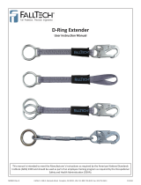
C. FALL CLEARANCE: a competent or qualied per-
son must calculate an appropriate fall clearance below
an elevated work area that is free from obstructions to
a potential fall, prior to beginning work. When calcu-
lating fall clearance the following must be considered:
C.1 Free Fall Distance: must be limited to a maxi-
mum of 6 ft. (Distance may vary by state. Check local
standards.)
C.2 Deceleration Distance: the vertical distance a
falling person travels, excluding lifeline elongation
and free fall distance, between the activation of the
PFAS and nal fall arrest.
The deceleration distance must be included in the calculation of total necessary fall clearance. Important: employ-
ment of a rope grab will increase the deceleration distance.
C.3 Height of Worker
C.4 Connecting Subsystem: the length of the connecting subsystem must be factored into the fall clearance dis-
tance.
C.5 Stretch: during a fall arrest and after a fall, a harness can stretch by approximately 1 ft. and shock absorbers can
elongate by an additional 4 ft.
C.6 Safety Factor: it is prudent to allow for an additional safety factor of 3 ft. below the fallen worker’s feet.
D. FALL PATH: this fall protection equipment requires an unobstructed fall path. Fall paths can be obstructed if the
user is positioned on a granular surface like sand or coal; and also by low pitched or cramped work areas where a user
may slide instead of fall.
E. SWING FALL: can occur when the worker moves laterally from the anchorage point. The impact force can cause
serious injury or death. To prevent the risk of swing fall the lanyard, lifeline or other anchorage connector must be in-
stalled to an anchor point that is above the user and that the user maintain a safe work zone that does not exceed 30°
on either side of anchor point. The risk of swing falls will signicantly increase when a self-retracting lifeline or other
variable length connecting subsystem is used.
F. SHARP EDGES: Avoid working where the equipment webbing will be in contact with an abrasive or sharp edge.
G. HAZARDS: Use of this equipment where surrounding hazards exist may result in injury to the user or damage to
the equipment. Some hazards include: high heat, severe cold, corrosive or caustic chemicals, high voltage power lines,
explosive or toxic gases, moving machinery, sharp edges or unstable overhead materials that could strike a user or fall
6 ft. Length
of Lanyard
4 ft.
Deceleration
Distance
18.5 ft. Total Fall Clearance
6 ft. Height
of Worker
3 ft.
Safety Factor
26
(1.0)
20
(0.8)
152
(6.0)
124
(4.9)
Back of
Worker
Before Fall
Front of Worker
After Fall
Energy
Absorber
Elongation
(4 ft.)
ANCHORAGE
Figure 1: Fall Clearance Diagram

protection system components. Important: Use caution when working near high voltage power lines; electricity can
pass through the metal components and could electrocute the user.
H. TEMPERATURE: this equipment is not designed for high temperature environments. Important: keep equipment
away from hot surfaces, excessive heat, ames or sparks.
I. IMPACT: Any component of a PFAS that has been subjected to fall arrest forces shall be removed from service and
destroyed.
J. SUSTAINED SUSPENSION: this equipment is not intended for use in sustained suspension applications.
K. RESCUE: Rescue protocol must be determined prior to use and training and put in writing by the company safety
professional. Rescue systems must be rigged so that no vertical free fall is possible during rescue. The employer shall
provide for prompt and safe rescue in the event of a fall.
2.3 USE
A. CONNECTING SUBSYSTEM
Connecting lanyards must be suitable for your application. Do not attach a snap hook directly to a horizontal lifeline
or to a webbing loop. The web loop of this lanyard must only be attached to other components with compatible con-
nections. When a web lanyard is used as a D-ring extension on a harness, connect the snap hook to the dorsal harness
connector. Always follow the manufacturer’s instructions supplied with each subsystem component. Follow the table
below for steps on connecting a lanyard.
A.1 Connection Steps
1. INSPECT 2. CONNECT TO BODY SUPPORT 3. CONNECT TO ANCHORAGE
Before each use
carefully inspect the
lanyard according to
the instructions listed
in Section 3.2.
Connect the snap hook of this lan-
yard to the dorsal D-ring of a pre-in-
spected harness.
Connect the web loop of the lanyard
end1 to an appropriate anchorage or
anchorage connector. Important: do
not connect the shock-absorbing end
to anchorage point.
Fall Arrest
Single Leg
Lanyard
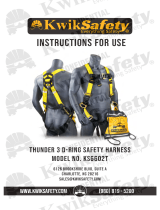
A.2 Limit risk of roll-out:
1. Do not use carabiner or snap hook that will not completely close and lock over the attachment. (Fig. A)
2. Do not connect to small rings or other non-compatible anchors (Fig. B)
3. Ensure that carabiner or snap hook has completely closed and fully engaged to the anchor point. (Fig. C)
4. Do not loop lanyard or rope through carabiner or snap hook and tie-back. (Fig. D)
5. Do not connect carabiners or snap hooks to other carabiners or snap hooks. (Fig. E and H)
6. Do not install more than one snap hook or carabiner into a single connection. (Fig. F)
7. Connect carabiner so that the load is only on the carabiner’s xed steel portion. Never allow load to be directed to
the gate. (Fig. G)
1 The non-shock absorbing end is the lanyard end.
WARNING: All PFAS are required to comply with OSHA and ANSI standards and limit free fall to 6 ft. or less. Consult lo-
cal government regulations for allowable free fall distances as they may vary between ANSI, OSHA, national and local
codes. Plan and conrm that there is adequate, unobstructed fall clearance to prevent the user from striking lower
levels. Avoid working above the anchorage level which increases the free fall distance.
WARNING
WARNING
WARNING: Rescue protocol must be determined prior to use and training and put in writing by the company safety professional.
Do not allow fall protection equipment to be used near any physical hazards like those mentioned in Section 2.2 F. If fall occurs,
the operator must await rescue and must not manipulate the shock-absorbing lanyard.

8. Do not use knots to attach car-
abiner.
9. Only attach fall protection sys-
tems to anchorages that meet the
application-specic criteria out-
lined in Section 1.5.
A.3 A competent person, fully
aware of applicable safety regula-
tions for use, inspection and main-
tenance should ensure all compo-
nents are installed correctly and
that connections are compliant
and compatible in size, shape and
strength to prevent injury to the
user or damage to the equipment.
See the anchorage manufacturer’s
instructions for more information
on making connections. Important:
a person other than the user should
verify that the harness dorsal D-ring
is properly connected to the user’s
lanyard prior to being exposed to a fall hazard.
3.0 INSPECTION
3.1 FREQUENCY
A. PRIOR TO USE: OSHA and ANSI Standards require that the user or a competent or qualied person inspect the all
fall protection equipment according to the inspection guidelines listed in Section 3.2 as well as all subsystem compo-
nents and connectors attached and/or used in conjunction with this equipment as per the Manufacturer’s Instructions.
B. ANNUALLY: ANSI/ASSE Z359.1 requires a formal inspection of all PFAS components and connectors be completed
by a competent or qualied person other than the user at least annually. This is subject to local, state, federal and pro-
vincial law, which can require more than one inspection a year. More frequent inspections by a competent person may
also be required based on the nature and severity of workplace conditions aecting the equipment and the modes of
use and exposure time of the equipment.
Inappropriate Connections
A. B. C. D.
E. F. G. H.
Figure 2: Inappropriate Connections
Table 2: ANSI Z359.14 Inspection Requirements
Types of Use Application Examples Conditions of Use Inspection Frequency by
a Competent Person
Infrequent to
light
Rescue & Conned space,
Factory maintenance
Good storage conditions, indoor or infre-
quent outdoor use, room temperature,
clean environments
Annually
Moderate to
heavy
Transportation, Residen-
tial construction, Utilities,
Warehouse
Fair storage conditions, indoor and
extended outdoor use, all temperatures,
clean or dusty environments
Semi-annually to
annually
Severe to contin-
uous
Commercial construction,
Oil & Gas, Mining
Harsh storage conditions, prolonged or
continuous outdoor use, all tempera-
tures, dirty environment
Monthly
WARNING
WARNING: If equipment fails inspection, do not attempt to alter or repair. If it is dirty follow instructions below.
ALL FALL PROTECTION EQUIPMENT THAT FAILS INSPECTION OR IS EXPOSED TO FALL ARREST FORCES MUST BE PER-
MANENTLY REMOVED FROM SERVICE AND DESTROYED.

B.1 Record: Record inspection results in this manual and on device label. Keep records on le. If in doubt about
the safety or condition of any equipment, immediately mark it “Do Not Use” and remove from service and destroy to
prevent accidental use. A user, competent or qualied person can remove any PFAS product from use.
C. AFTER A FALL ARREST: IF EQUIPMENT IS EXPOSED TO FALL FORCES, IT MUST BE IMMEDIATELY REMOVED FROM
SERVICE AND DESTROYED.
3.2 INSPECTION STEPS
B.1 Visually inspect the lanyard hardware (snap hooks, adjusters, thimbles): These items must not be damaged or
broken or show signs of corrosion, defects, cracks, sharp edges, burns, dents, deformation, distortion or missing
parts. Ensure the connecting hooks work properly. The hook gates must move freely and lock upon closing. Ensure
any adjusters work properly.
B.2 Inspect lanyard for chemical or heat damage indicated by brown, discolored, or brittle areas. Check for bad
smell or mildew. Check for ultraviolet damage, indicated by discoloration and the presence of splinters and slivers on
the rope surface. Inspect the lanyard per the following as applicable:
• Webbing and Stitching: Visually inspect to ensure that webbing is free of: kinks, broken strands, cuts, burns, cor-
rosion, welding splatter, paint coating, excessive abrasion and knots throughout its length. Inspect for excessive
soiling and rust staining. Check for pulled or cut stitches which may be an indication the lanyard has been impact
loaded and must be removed from service
B.3 If present, inspect the energy absorber to determine if it has been activated. There should be no evidence of
elongation. Ensure energy absorber cover is secure and not torn or damaged
B.4 Inspect the labels. All labels must be present and fully legible. All labels and markings must be fully intact and
easy to read. Never remove a label from a piece of equipment.
B.5 Inspect each system component or subsystem per the Manufacturer’s Instructions.
B.6 Log inspection on device label and on the last page of the manual.
4.0 MAINTENANCE
4.1 CLEANING: Periodically or as needed. Clean this equipment with cold water and mild soap. After washing, thor-
oughly rinse with clear water and hang to dry (away from sunlight or high heat).
Important: an excessive buildup of dirt, chemicals, sweat or paint may weaken or damage the functionality of equipment. Do
not machine wash or clean with petroleum, solvent agents, acids etc.
4.2 STORAGE: Store in a cool, dry, clean environment. Precautions should be taken to avoid prolonged exposure to
sunlight and/or uorescent lights, which can degrade equipment. Never store in areas where the harness or lanyard
could come into contact with chemicals, moisture or other corrosive substances. This equipment must be kept away
from contact with heat or sharp, abrasive surfaces.
Important: Do not store in sealed plastic bags. Inspect the equipment according to Section 3.2 after extended storage prior to
issuing .
WARNING
WARNING: EXTREME WORKING CONDITIONS MAY REQUIRE THAT THE USER INSPECT EQUIPMENT MORE FREQUENTLY. READ AND
FOLLOW ALL INSTRUCTIONS, MARKINGS AND/OR LABELS ON THIS EQUIPMENT. MARKINGS AND LABELS SHOULD BE INTACT AND
LEGIBLE.

RECORD ALL INSPECTIONS:
Date of Manufacture:____________ Date Put In Service:____________
Serial # Date Inspector Pass-Fail Maintenance Performed
5.0 LABELS

KONG USA, LLC
401-253-3759
WWW.KONG.IT
/