Page is loading ...

I277 Rev. B / MFP9720157
20 August 2012

2
1.0 Purpose..................................................................................... 3
2.0 General Requirements.............................................................. 3-5
2.1 General Warnings / 2.2 Warnings and Limitations
3.0 System Compatibility................................................................. 5-6
3.1 Personal Fall Arrest System Components / 3.2 Component Warnings and Limitations
4.0 Operation................................................................................. 7
5.0 Installation................................................................................. 8-11
5.1 General Installation and Making Connections
5.2 Installation of MightEvac to Mounting Bracket
5.3 Installation Procedure to Tripod
5.4 Installation Procedure to DuraHoist Mast or Davit Arm
5.5 Installation Procedure to Davit System
5.6 Installation Procedure to Quad Pod
5.7 Installation Procedure to Wall Mount
6.0 Calculating Fall Clearance Distance......................................... 12-13
7.0 Training..................................................................................... 13
8.0 Inspection and Maintenance..................................................... 14-15
8.1 Inspection and Operation Checkpoints / 8.2 Maintenance
3URGXFW6SHFL¿FDWLRQV
Product Labels.......................................................................... 44-45
Inspection and Maintenance Log.............................................. 46
Table des Matières
1.0 Objet......................................................................................... 16
2.0 Exigences, Mises en Garde et Restrictions Générales............. 16-18
3.0 Compatibilité du Système......................................................... 18-19
4.0 Fonctionnement........................................................................ 20
5.0 Installation................................................................................. 21-24
6.0 Calcul de la Distance de la Zone de Dégagement en cas de Chute.... 24-26
7.0 Formation.................................................................................. 26
8.0 Inspection et Entretien.............................................................. 27-28
Fiche Technique sur les Produits........................................... 42-43
Étiquettes sur les Produits........................................................ 44-45
Registre D’inspection et D’entretien.......................................... 46
Índice
1.0 Propósito................................................................................... 29
2.0 Requisitos, Advertencias y Limitaciones Generales................. 29-31
3.0 Compatibilidad del Sistema...................................................... 31-32
4.0 Manejo...................................................................................... 33
5.0
Instalación.................................................................................... 34-37
6.0 Cómo Calcular la Distancia del Margen de Caída.................... 38-39
7.0 Entrenamiento........................................................................... 39
8.0 Inspección y Mantenimiento..................................................... 40-41
(VSHFL¿FDFLRQHVGHORV3URGXFWRV
Etiquetas de los Productos....................................................... 44-45
Registro de Inspección y Mantenimiento.................................. 46
Table of Contents

User Instructions - English
3
All warnings and instructions shall be
provided to authorized persons/users.
All authorized persons/users must
reference the regulations governing
RFFXSDWLRQDOVDIHW\LQFOXGLQJFRQ¿QHG
space regulations), as well as applicable
ANSI or CSA standards. Please refer to
SURGXFWODEHOLQJIRULQIRUPDWLRQRQVSHFL¿F
OSHA regulations, and ANSI and CSA
standards met by product.
All authorized persons/users of this equip-
PHQWPXVWEHWUDLQHGLQSURSHUFRQ¿QHG
space procedures.
Proper precautions should always be taken to
remove any obstructions, debris, material, or
other recognized hazards from the work area
that could cause injuries or interfere with the
operation of the system.
All equipment must be inspected before
each use according to the manufacturer’s
instructions.
All equipment should be inspected by a
TXDOL¿HGSHUVRQRQDUHJXODUEDVLV
To minimize the potential for accidental
disengagement, a competent person must
ensure system compatibility.
Equipment must not be altered in any
way. Repairs must be performed only by
the manufacturer, or persons or entities
authorized in writing by the manufacturer.
Any product exhibiting deformities, unusual
wear, or deterioration must be immediately
discarded.
Any equipment subject to a fall must be
removed from service.
1.0 Purpose
The Miller MightEvac
®
Self-Retracting Lifeline with Emergency Retrieval Hoist is a retractable
GHYLFHGHVLJQHGWREHXVHGE\SHUVRQQHOIRUIDOOSURWHFWLRQLQFRQ¿QHGVSDFHDSSOLFDWLRQVZLWKD
quick-activating retrieval mechanism for emergency evacuation.
2.0 General Requirements,
Warnings and Limitations
Questions?
CALL
1.800.873.5242
It is crucial that the authorized person/user of this equipment read and understand these instruc-
tions. In addition, federal law requires employers to ensure that all users are trained in the
SURSHULQVWDOODWLRQXVHLQVSHFWLRQDQGPDLQWHQDQFHRIIDOOSURWHFWLRQDQGFRQ¿QHGVSDFHHTXLS-
ment. Fall protection training should be an integral part of a comprehensive safety program.
Proper use of fall arrest systems can save lives and reduce the potential of serious injuries from
a fall. The user must be aware that forces experienced during the arrest of a fall or prolonged
suspension may cause bodily injury. Consult a physician if there is any question about the
user’s ability to use this product. Pregnant women and minor children must not use this product.
Thank you for your purchase of Miller fall protection equipment manufactured by Honeywell Safety
Products. Miller brand products are produced to meet the highest standards of quality at our ISO
FHUWL¿HGIDFLOLW\0LOOHUHTXLSPHQWZLOOSURYLGH\RXZLWK\HDUVRIXVHZKHQFDUHGIRUSURSHUO\
Thank You
All persons using this equipment must read, understand and follow all
instructions. Failure to do so may result in serious injury or death. Do
not use this equipment unless you are properly trained.
WARNING
!

User Instructions - English
4
CAPACITY
For use by ONE person only in both
fall protection and rescue applications.
Maximum capacity is 310 lbs. (140.6kg),
including body weight, clothing and tools,
unless labeled otherwise. — DO NOT
EXCEED THIS WEIGHT.
When used with a Miller 928LS shock
absorber, Miller brand self-retracting
lifelines are rated to *400 lbs. (181.4kg)
maximum capacity in overhead
installation applications. The shock
absorber must be attached between
the user’s harness back D-ring and the
self-retracting lifeline. Additional fall
FOHDUDQFHLVQHHGHGIRUWKLVFRQ¿JXUDWLRQ
Refer to the label on the shock absorber
to determine its maximum elongation/
deceleration distance and add this
factor to your self-retracting lifeline fall
clearance calculation.
*If the system is used by an employee having
a combined tool and body weight between 310
lbs. (140.6 kg) and 400 lbs. (181.4 kg), then the
employer must appropriately modify the criteria
and protocols to provide proper protection for such
heavier weights, or the system will not be deemed
to be in compliance with the requirements of OSHA
1926.502(d)(16). [ANSI capacity range is 130 lbs.-
310 lbs. (59kg-140,6kg).]
Force required to operate rescue features
when device is loaded to capacity is 22
lbs. (98N).
The authorized person/user shall have
a rescue plan and the means at hand to
implement it when using this equipment.
Never use fall protection equipment for
purposes other than those for which it was
designed. Fall protection equipment should
never be used for towing or hoisting.
All synthetic material must be protected from
VODJKRWVSDUNVRSHQÀDPHVRURWKHUKHDW
sources. The use of heat resistant materials
is recommended in these applications.
Environmental hazards should be considered
when selecting fall protection equipment.
Equipment must not be exposed to
environmental hazards and chemicals which
may produce a harmful effect. Use in highly
corrosive or caustic environments dictates
a more frequent inspection and servicing
program to ensure the integrity of the device
is maintained.
Do not allow equipment to come in contact
with anything that will damage it including, but
not limited to, sharp, abrasive, rough or high-
temperature surfaces, welding, heat sources,
electrical hazards, or moving machinery.
Do not expose the equipment to any hazard
which it is not designed to withstand. Consult
the manufacturer in cases of doubt.
Always check for obstructions below the work
area to make sure potential fall path is clear.
Allow adequate fall clearance below the work
surface.
Never remove product labels, which include
important warnings and information for the
authorized person/user.
2.2 Warnings and Limitations
LIFELINE RETRACTION & LOCKING
Do not use the device if it does not retract.
Always maintain tension on the lifeline
while retracting.
Device must be tested for locking before
each use. Do not use the device if the
brakes do not engage.
USE
This device is designed for overhead
installation applications and applications
whereby the unit is used in conjunction
with a mounting bracket and installed to
Honeywell-approved anchorages, such as
a tripod or davit system.
Do not use this device for horizontal use
or with horizontal lifeline systems, unless
approved by the manufacturer.
Never work above the device.
The device should be installed and used
in such a manner as to minimize the
potential for a swing fall.
Never allow lifeline to become slack while
being used for fall protection or while in
rescue mode.
Do not allow lifeline in any application
to bend or be subjected to fall arresting
forces over structural members or edges.
Never use the device as a restraint or
positioning device.

User Instructions - English
5
Three key components of the Personal Fall Arrest System (PFAS) need to be in place and
properly used to provide maximum worker protection.
ANCHORAGE/ANCHORAGE CONNECTOR
7KH¿UVWFRPSRQHQWLVWKHDQFKRUDJHDQFKRUDJHFRQQHFWRU
The anchorage, also referred to as the anchor point or tie-off
point, is a secure point of attachment for connecting devices
and must be capable of supporting 5,000 lbs. (22.2kN) per
worker or meet OSHA requirements for a safety factor of two,
such as an I-beam or other support structure. An anchorage
connector, such as the cross-arm strap, D-bolt or rebar
hook anchor, is sometimes necessary to make a compatible
connection between the connecting device and the anchorage.
BODY WEAR
The second system component is the personal protective gear
worn by the worker while performing the job. The only form of
body wear acceptable for fall arrest is the full-body harness.
Full-body harnesses are engineered to aid in the arrest of a
free fall and must be worn in all situations where workers are
exposed to a potential free fall.
CONNECTING DEVICE
The third component of the system is the connecting
device, the critical link which joins the body wear to the anchorage/anchorage connector. The
most important feature of the connecting device is the built-in shock absorber. Whether the
connecting device is a shock-absorbing lanyard or self-retracting lifeline, they are designed to
dramatically reduce fall arrest forces. Rope, web or wire rope lanyards being used for fall arrest
MUST be used in conjunction with a shock absorber (i.e., Miller SofStop pack).
Individually, none of these components will provide protection from a fall. However,
when used properly and in conjunction with each other, they form a Personal Fall Arrest
System that becomes vitally important to safety on the job site.
3.0 System Compatibility
The Miller MightEvac Self-Retracting Lifeline is designed for use with Honeywell-approved
components only. Substitution or replacement with non-approved component combinations or
subsystems or both may affect or interfere with the safe function of each other and endanger
the compatibility within the system. This incompatibility may affect the reliability and safety of the
total system.
A
B
C
3.1 Personal Fall Arrest System Components
The retrieval mechanism in this device
is FOR EMERGENCY USE ONLY. Do not
use for routine hoisting of personnel or
materials.
MAINTENANCE
Do not lubricate this device.
The device must be kept clean and free of
contaminants.
This unit must be removed from service
if any part of the system appears to be
damaged or does not pass inspection, or if
the unit has been subjected to the forces of
arresting a fall or affecting a rescue.
Do not attempt to service this device. If the
device does not operate properly or requires
repairs, return the device to the equipment
manufacturer, or service center authorized
in writing by the manufacturer, for repairs.

User Instructions - English
6
ANCHORAGES/ANCHORAGE CONNECTORS
$QFKRUDJHVPXVWEHFDSDEOHRIVXSSRUWLQJSRXQGVN1SHUZRUNHUor meet OSHA
UHTXLUHPHQWVIRUDVDIHW\IDFWRURItwo.
$QFKRUDJHUHTXLUHPHQWVEDVHGRQ$16,DUHDVIROORZV
)RUIDOODUUHVWV\VWHPVDQFKRUDJHVPXVWZLWKVWDQGDVWDWLFORDGRIOEVN1IRU
QRQFHUWL¿HGDQFKRUDJHVRUWZRWLPHVWKHPD[LPXPDUUHVWLQJIRUFHIRUFHUWL¿HGDQFKRUDJHV
)RUUHVFXHV\VWHPVRQO\DQFKRUDJHVPXVWZLWKVWDQGDVWDWLFORDGRIOEVN1
IRUQRQFHUWL¿HGDQFKRUDJHVRU¿YHWLPHVWKHDSSOLHGORDGIRUFHUWL¿HGDQFKRUDJHV1RWH
When an anchorage may be utilized for both fall arrest AND rescue, the fall arrest load
requirement applies.)
:KHQPRUHWKDQRQHV\VWHPLVDWWDFKHGWRDQDQFKRUDJHWKHDERYHDQFKRUDJHVWUHQJWKV
must be multiplied by the number of systems attached to the anchorage.
$OZD\VZRUNGLUHFWO\XQGHUWKHDQFKRUSRLQWWRDYRLGDVZLQJIDOOLQMXU\
When selecting an anchorage point, always refer to the fall clearance calculation information
provided with the connecting device to ensure that the anchorage point is at a height that will
not allow a user to strike a lower level should a fall occur. Remember that shock absorbers
will elongate when subjected to fall arrest forces (refer to the labels/instructions provided with
the shock absorber for additional details).
$QFKRUDJHFRQQHFWRUPXVWEHFRPSDWLEOHZLWKVQDSKRRNRUFDUDELQHUDQGPXVWQRWEH
capable of causing a load to be applied to the gate (keeper).
BODY WEAR
7KHRQO\IRUPRIERG\ZHDUDFFHSWDEOHIRUIDOODUUHVWLVWKHIXOOERG\KDUQHVV
,WLVLPSHUDWLYHWKDWWKHKDUQHVVEHZRUQSURSHUO\9LVXDOO\FKHFNDOOEXFNOHVWRDVVXUHSURSHU
and secure connections before each use. All straps must be connected and adjusted to
SURYLGHDVQXJ¿W
)DOOSURWHFWLRQFRQQHFWLQJGHYLFHVVKRXOGEHDWWDFKHGWRWKHEDFN'ULQJRIWKHIXOOERG\
harness. A front D-ring attachment element may be used for fall arrest only in rescue, work
SRVLWLRQLQJURSHDFFHVVDQGRWKHU$16,=UHFRJQL]HGDSSOLFDWLRQVZKHUHWKHSHUVRQDOIDOO
arrest system limits the maximum free fall distance to 2 ft. (0.6m) and limits the maximum arrest
force to 900 lbs. (4.0kN).
6LGHDQGIURQW'ULQJVVKRXOGEHXVHGIRUSRVLWLRQLQJRQO\1RWHIURQW'ULQJH[FHSWLRQ
above.); shoulder D-rings should be used for retrieval, raising or lowering only.
1HYHUDWWDFKUHEDUSHOLFDQKRRNVWRDKDUQHVV'ULQJ
%RG\EHOWVVKRXOGEHXVHGIRUSRVLWLRQLQJRQO\
CONNECTING DEVICES
0DNHRQO\FRPSDWLEOHFRQQHFWLRQV
8VHRQO\FRQQHFWLQJGHYLFHVFRQWDLQLQJORFNLQJVQDSKRRNVRUDXWRORFNLQJFDUDELQHUV
&RQQHFWLQDPDQQHUWKDWOLPLWVIUHHIDOOWRWKHVKRUWHVWSRVVLEOHGLVWDQFH>IWP
maximum]
$OZD\VYLVXDOO\FKHFNWKDWHDFKVQDSKRRNDQGFDUDELQHUIUHHO\HQJDJHVWKHKDUQHVV'ULQJRU
anchor point/anchorage connector, and that its gate (keeper) is completely closed and locked.
Never disable or restrict locking keeper or alter connecting device in any way.
0DNHVXUHVQDSKRRNFDUDELQHULVSRVLWLRQHGVRWKDWLWVJDWHLVQHYHUORDGEHDULQJ
7KHXVHRIVKRFNDEVRUEHUVLVUHTXLUHGWRUHGXFHIDOODUUHVWIRUFHV$OO0LOOHUVKRFN
absorbers, shock-absorbing lanyards, and self-retracting lifelines limit maximum fall arrest
forces to 1800 lbs. (8kN) or less.
1HYHUDOORZDODQ\DUGOLIHOLQHWRSDVVXQGHURUHQWZLQHDURXQGWKHXVHU¶VDUPVOHJVQHFNRU
any other obstacle.
'RQRWWLHNQRWVLQODQ\DUGVRUOLIHOLQHVRUZUDSDURXQGVKDUSURXJKHGJHVRUVPDOOGLDPHWHU
structural members.
'RQRWDWWDFKPXOWLSOHODQ\DUGVWRJHWKHURUDWWDFKDODQ\DUGEDFNRQWRLWVHOIXQOHVVLWLV
VSHFL¿FDOO\GHVLJQHGIRUWKDWSXUSRVH
3.2 Component Warnings and Limitations

User Instructions - English
7
4.0 Operation
Retrieval Operation
Ɇ)25(0(5*(1&<86(21/<Ɇ
The MightEvac retrieval mechanism is to be used only in the event of an
emergency. Do not use for routine hoisting of personnel or materials.
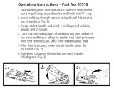
127(,WLVUHFRPPHQGHGWRSXOORXW
several feet of lifeline and hold in position
before engaging retrieval mechanism.
Always maintain tension on the lifeline
while in retrieval mode.
Pull out on the plunger pin until the ratchet
handle pops outward. It may be necessary to
rotate the handle slightly to fully engage the in-
ternal gears. The plunger pin should snap back
into its original position when the gears are fully
engaged. The unit is now in retrieval mode.
127($UHVFXHPD\EHH[HFXWHGHLWKHU
by raising or lowering a person to safety.
TO RAISE: While maintaining light tension on
the lifeline, rotate the ratchet handle counter-
clockwise (CCW) to crank the lifeline into the
housing.
TO LOWER: To extend lifeline from the housing
(to lower), rotate ratchet handle in clockwise
(CW) direction. [NOTE: If the internal brak-
ing mechanism has been activated, such as
ZLWKDIDOODUUHVWLWLVQHFHVVDU\WR¿UVWFUDQN
in the upward direction (CCW) for one-half to
one rotation, then reverse the direction (CW) to
begin lowering. A minimum of 75 lbs. (34kg) is
required for lowering.]
:$51,1*$OZD\VHQVXUHWKDWWKH
plunger pin has returned completely into
the locked position when changing the
unit from retractable to retrieval mode.
Do not use the unit if it will not hold the
load while in retrieval mode.
MAY RESULT IN SERIOUS OR FATAL INJURY
WARNING! FAILURE TO OBSERVE INSTRUCTIONS
PAT. NO. 5,771,993
SELF-RETRACTING LIFELINE WITH EMERGENCY RESCUE
®
? Always use and inspect unit in accordance
with manufacturer’s instructions.
? Do not use as a restraint or positioning
device.
? Use only with attachment fittings and safety
harness recommended by manufacturer.
? Always connect the hook directly to
attachment point on harness.
? Guard against swing falls by keeping the
lifeline vertically overhead. Never work
above the device.
? Keep user and other workers from becoming
entangled in lifeline.
? Do not allow lifeline to drag over
obstructions.
? Never clamp off or stand on the lifeline.
? Do not allow the lifeline to become slack.
? Do not allow cable, rope or webbing
lifelines to come in contact with anything
that will damage the lifeline including, but
not limited to, sharp, abrasive, rough or
high-temperature surfaces, welding, heat
sources, electrical hazards, or moving
machinery.
? Wear gloves when inspecting or handling
cable lifelines.
? Check lifeline for damage, frays, or cuts that
will reduce the strength.
? Maintain tension on the lifeline while letting
it retract after disconnecting from worker.
? Servicing must only be performed by the
manufacturer or an approved agent.
WARNING: Manufacturer’s instructions supplied with this product at time of shipment must be followed: Failure to do so could result in serious
injury or death. Only for use by ONE person as a personal fall arrester. Device must be taken out of service for inspection and recertification
after arresting a fall or when the impact indicator has been activated. Contact Miller Fall Protection if instruction manual is needed.
ADVERTENCIA: Deben seguirse los instrucciones del fabricate provistas con este producto al momento de despacho: El no hacerio
puede resultar en lesiones graves o la muerte. Solo para el uso por UNA SOLA persona coma detentor personal contra caidas. El
dispositivo debe retirarse del servicio para ser inspeccionado y recertification luego de haber detenido una caida o cuando se haya
activado el indicator de impacto. Si se requiere el manual de instrucciones consulte con Miller Fall Protection.
ADVERTISSEMENT: Vous devez respecter les instructions du fabricant que vous avez recues avec le produit: Dans le cas
contraire, vous risquez de blessures graves ou meme lamort. Utiliser seulement par UNE personne comme arret de chute
personnelle. L’appareil doit etre mis hors d’utilisation pour inspection et recertification apres avoir arrete une chute ou
lorsque l’indicateur d’impact a ete active. Contactez Miller Fall Protection si vous avez besoin d’un nouveau manuel.
LB388
Rev. D
MFP9350111
PLUNGER PIN
RATCHET
HANDLE
Self-Retracting Lifeline Operation
To return the unit to the retractable mode, remove the weight from the lifeline and secure the end of
the lifeline as it will begin to retract once the internal gears are disengaged. Pull out on the plunger
pin and hold. Push inward on the ratchet handle, where it connects to the gear shaft, to disengage
the gears and let pin drop into the locked position.

User Instructions - English
8
Fig. 1
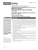
5.2 Installation of MightEvac
to Mounting Bracket
(Ref. Fig. 1)
Step 1: Remove red, round protective stickers from both sides of the MightEvac unit.
Step 2: Insert attachment swivel of the unit into bracket as shown.
Step 3: Slide the unit forward until the threaded holes in the housing (where stickers were removed)
are aligned with the holes in the front of the bracket as shown.
NOTE: The carrying handle of the unit must be in the upward position away from the bracket.
Insert the fastener through the
lockwasher, spacer and hole in the
bracket. Tighten to 8 plus or minus
one (1) ft.-lbs. (96 plus or minus 12
in.-lbs.). Repeat for opposite side.
Step 4: Insert the pushpin through the
bracket in the holes provided. This
securely attaches the unit to the
bracket. Ensure the pushpin is
securely through both holes and
remains in place.
Step 5: Attach the unit with bracket to an
approved Miller anchoring device
and secure with the pushpins
provided. Refer to installation
procedures in sections 5.3, 5.4, 5.5, 5.6 and 5.7 of this manual.
To remove the unit, simply reverse the above procedures.
5.0 Installation
5.1 General Installation and Making Connections
For general fall protection, connect the lifeline
end connector (i.e., snap hook) to the back
D-ring on the full-body harness.
The MightEvac Self-Retracting Lifeline must be
mounted to an overhead anchorage by the attachment
swivel using a locking carabiner or other Miller approved
anchorage connector, or it must be used in conjunction
with a Miller mounting bracket which is then installed
on a tripod, davit system, quad pod, or wall mount. The
anchorage must be capable of supporting a 5,000 lb.
(22.2kN) tensile load or meet OSHA 1926.502 require-
ments for a safety factor of two. Review all warnings
and instructions when selecting a mounting location.
$1&+25$*(
&211(&725
/2&.,1*
&$5$%,1(5
$1&+25$*(
MAY RESULT IN SERIOUS OR FATAL INJURY
WARNING!FAILURE TO OBSERVE INSTRUCTIONS
PAT. NO. 5,771,993
SELF-RETRACTING LIFELINE WITH EMERGENCY RESCUE
®
? Always use and inspect unit in accordance
with manufacturer’s instructions.
? Do not use as a restraint or positioning
device.
? Use only with attachment fittings and safety
harness recommended by manufacturer.
? Always connect the hook directly to
attachment point on harness.
? Guard against swing falls by keeping the
lifeline vertically overhead. Never work
above the device.
? Keep user and other workers from becoming
entangled in lifeline.
? Do not allow lifeline to drag over
obstructions.
? Never clamp off or stand on the lifeline.
? Do not allow the lifeline to become slack.
? Do not allow cable, rope or webbing
lifelines to come in contact with anything
that will damage the lifeline including, but
not limited to, sharp, abrasive, rough or
high-temperature surfaces, welding, heat
sources, electrical hazards, or moving
machinery.
? Wear gloves when inspecting or handling
cable lifelines.
? Check lifeline for damage, frays, or cuts that
will reduce the strength.
? Maintain tension on the lifeline while letting
it retract after disconnecting from worker.
? Servicing must only be performed by the
manufacturer or an approved agent.
WARNING: Manufacturer’s instructions supplied with this product at time of shipment must be followed: Failure to do so could result in serious
injury or death. Only for use by ONE person as a personal fall arrester. Device must be taken out of service for inspection and recertification
after arresting a fall or when the impact indicator has been activated. Contact Miller Fall Protection if instruction manual is needed.
ADVERTENCIA: Deben seguirse los instrucciones del fabricate provistas con este producto al momento de despacho: El no hacerio
puede resultar en lesiones graves o la muerte. Solo para el uso por UNA SOLA persona coma detentor personal contra caidas. El
dispositivo debe retirarse del servicio para ser inspeccionado y recertification luego de haber detenido una caida o cuando se haya
activado el indicator de impacto. Si se requiere el manual de instrucciones consulte con Miller Fall Protection.
ADVERTISSEMENT: Vous devez respecter les instructions du fabricant que vous avez recues avec le produit: Dans le cas
contraire, vous risquez de blessures graves ou meme lamort. Utiliser seulement par UNE personne comme arret de chute
personnelle. L’appareil doit etre mis hors d’utilisation pour inspection et recertification apres avoir arrete une chute ou
lorsque l’indicateur d’impact a ete active. Contactez Miller Fall Protection si vous avez besoin d’un nouveau manuel.
LB388
Rev. D
MFP9350111
$77$&+0(17
6:,9(/
0,*+7(9$&
:,7+02817,1*%5$&.(7

User Instructions - English
9
Fig. 2a
5.3 Installation Procedure to Tripod (Ref. Fig. 2a and 2b)
Fig. 2b
Step 1: Place bracket hook over adjustment pin.
Step 2: Rotate bracket toward Tripod leg until the top holes of the bracket pass the Tripod leg and
insert pin completely through both sides of the bracket. (NOTE: This pin will pass behind the
Tripod leg, not through it--see Fig. 2b.)
Step 3: Align the bottom holes in the bracket with holes in the Tripod leg and insert pin through bracket
and Tripod leg. Be sure the pin is completely through both the bracket and Tripod leg.
To remove the device, simply reverse the installation procedure. :$51,1* Be careful not to remove
the pin that collapses the Tripod leg, as serious injury may occur.

User Instructions - English
10
5.4 Installation Procedure to DuraHoist Mast
(Ref. Fig. 3a, 3b and 3c) or Davit Arm (Ref. Fig. 4)
Fig. 3b Fig. 3cFig. 3a
Fig. 4
Installation to DuraHoist Davit Arm
Step 1: Install DuraHoist mounting bracket DH-AP-11 to
davit arm per DuraHoist Instructions.
Step 2: Follow steps 2 through 4 above to secure Might-
Evac bracket to DuraHoist bracket.
To remove the device, simply reverse the installation
procedure.
Installation to DuraHoist Mast
Step 1: Install DuraHoist mounting bracket DH-19-MILLER to mast per DuraHoist Instructions.
Step 2: On the MightEvac bracket, insert only the top pin.
Step 3: Holding the MightEvac unit by the handle on the back and making sure the inserted pin is on
the top half of the bracket, hang the MightEvac onto the DuraHoist bracket.
Step 4: Secure by inserting the second pin through the bottom hole sets of both the DuraHoist and the
MightEvac brackets.
To remove the device, simply reverse the installation procedure.

User Instructions - English
11
Fig. 7
5.6 Installation Procedure
to Quad Pod (Ref. Fig. 6)
Fig. 6
5.7 Installation Procedure to Wall Mount (Ref. Fig. 7)
5.5 Installation Procedure
to Davit System (Ref. Fig. 5)
Fig. 5
Step 1: Place bracket over Davit System, align the top
holes of the bracket with the hole of the Davit
System and insert pin completely through bracket
and Davit System.
Step 2: Align the bottom holes of the bracket with the
holes in the Davit System. Insert the pin com-
pletely through the bracket and the Davit System.
To remove the device, simply reverse the installation
procedure.
Step 1: Place bracket over tubing of Quad Pod and align the
bottom holes of the bracket with the desired holes
in the tubing of the Quad Pod. Insert pin completely
through both the bracket and tubing of the Quad Pod.
Step 2: Push pin through the top holes of the bracket passing
behind the tubing of the Quad Pod. Make sure pin
goes completely through both sides of the bracket.
To remove the device, simply reverse the installation procedure.
Step 1: Place bracket over tubing of Wall Mount, align the
bottom holes of the bracket with the desired hole in
the Wall Mount and insert pin completely through
the bracket and tubing of the Wall Mount.
Step 2: Push pin through the top holes of the bracket
passing behind the tubing of the Wall Mount. Make
sure pin goes completely through both sides of the
bracket.
To remove the device, simply reverse the installation
procedure.

User Instructions - English
12
Self-Retracting Lifeline Fall Clearance Calculation
[Calculation taken from work level]
Maximum Arrest Distance
+ (Non-Standing Work Position Factor)
+ (Swing Fall Factor)
+ 3 ft. (.9m) Safety Factor
= Required Fall Clearance
6.0 Calculating Fall Clearance Distance
It is essential to understand how to calculate the fall clearance distance for each work
application to avoid contact with a lower level. Use the following calculation to determine
Required Fall Clearance.
IMPORTANT NOTES:
The self-retracting lifeine must be anchored overhead to ensure the accuracy of the fall
clearance calculation and related information.
It is important to understand that other factors, such as whether the user is performing
work in a standing, crouched or lying down position and/or whether the user is work
-
ing directly below the anchor point or at an angle, can affect fall distance when using a
retractable device.
The self-retracting lifeline fall clearance calculation assumes the user is standing. If the
user will be performing work in a crouched or kneeling position, an additional 3 ft. (.9m)
of fall clearance is required. If the user will be performing work in a lying down position,
DQDGGLWLRQDOIWPRIIDOOFOHDUDQFHLVUHTXLUHG
The self-retracting lifeline fall clearance calculation also assumes the user is working
directly below the anchor point, minimizing any possibility for a swing fall. In a swing fall
situation, the total fall distance will be greater than if the user were working directly below
the anchor point. In some applications, it may not be possible to work directly below the
anchor point. In such a case, the worker must increase the fall clearance distance to ac
-
count for the swing fall factor. In any case, the worker must not be exposed to a potential
swing fall where contact with another object may occur.
The maximum arrest distance (free fall + deceleration) varies by retractable. Always refer
WRWKHODEHOVRQWKHVSHFL¿FXQLWWRGHWHUPLQHWKHPD[LPXPDUUHVWGLVWDQFH
CAUTION: Read all notes and re-
fer to all self-retracting lifeline fall
clearance diagrams and labels
to determine exact required fall
clearance for your application.
(See Fig. 8a, 8b, 8c & 8d.)
Fig. 8a

User Instructions - English
13
Add 3 ft (.9m) of fall clearance
to calculation if user may
be working in a crouched or
kneeling position.
Add 5 ft. (1.5m) of fall clear-
ance if user may be working
in a lying down position.
Worker must not be exposed
to a swing fall hazard.
If there is any question
about calculating fall clearance distance,
please contact Honeywell Technical Services:
SUHVV
Whenever a worker may not be working
directly under the anchor point or may be
moving back and forth from the vertical of
the unit, the swing fall factor must be in-
cluded in the fall clearance calculation. Fall
clearance distance will increase according
WRWKHVSHFL¿FVRIWKHVZLQJIDOOFRQGLWLRQV
Honeywell Technical Services can help you
calculate the added fall clearance required...
call 1-800-873-5242 (press 4).
Fig. 8b
Fig. 8c
Fig. 8d
7.0 Training
The purchaser of this equipment must ensure that all personnel using this equipment are familiar
with these instructions and are properly trained in the operation, limitations, installation, inspec-
tion and maintenance of this product. Training should be conducted periodically and without
exposing the trainee to a fall hazard.
NOTE: Excessive training on this device will cause the gears in the unit to wear, thus reducing
its life expectancy and will consequently require more frequent servicing. The retrieval mecha-
nism in this device is for emergency use only. Do not use for routine hoisting of personnel or
materials.
Miller Training can provide the knowledge and skills necessary to achieve a safe, more productive
work environment. For more information, contact a representative today at 800-873-5242.

User Instructions - English
14
8.0 Inspection and Maintenance
8.1 Inspection and Operation Checkpoints
WARNING: The user must perform the following operation checkpoints and
inspections prior to each use. In addition, a competent person must inspect
equipment at regular intervals, at least annually.*
[*ANSI Z359.14 provides additional inspection requirements based on type of use and conditions of use. Refer
to 6.1 Inspection and Appendix A: Inspection Requirements for compliance with the standard.]
CAUTION: Always wear gloves when inspecting wire rope/cable units;
broken strands can cause injury!
'HYLFH+RXVLQJDQG3DUWV0RXQWLQJ%UDFNHW Inspect the unit for loose fasteners and bent,
cracked, distorted, worn, malfunctioning or damaged parts.
/LIHOLQH
a. With the device in the mounted position, test the lifeline retraction and tension by pulling out several
feet of the cable and allow to retract back into the unit. Always maintain a light tension on the cable
as it retracts. The lifeline should pull out freely and retract all the way back into the unit.
If the lifeline does not pull out smoothly or sticks when retracting, pull all the cable out of the
housing and allow it to retract slowly under tension. Do not use the unit if the lifelines does not
retract properly.
b. The lifeline should be checked regularly for signs of damage. Inspect entire length for cuts, burns,
corrosion, kinks, frays, worn areas, broken strands or chemical damage.
%UDNLQJ0HFKDQLVP The braking mechanism can be tested by grasping the lifeline ABOVE
the load indicator and applying a sharp steady pull downward which will engage the brakes.
There should be no slippage of the lifeline while the brakes are engaged. Once tension is
released, the brakes will disengage and the unit will return to the retractable mode.
6QDS+RRN Inspect the snap hook closely for damage, distortion,
cracks, corrosion, or pitted surfaces. The snap hook gate (keeper)
should seat into the nose without binding and should not be bent,
GLVWRUWHGRUREVWUXFWHG7KHJDWHVSULQJVKRXOGH[HUWVXI¿FLHQWIRUFH
WR¿UPO\FORVHWKHJDWH7KHJDWHORFNLQJPHFKDQLVPPXVWSUHYHQW
the gate from opening when closed. The snap hook swivel should
operate smoothly.
/RDG,QGLFDWRU Inspect the load indicator for signs of activation.
The load indicator is located in the swivel of the snap hook. The
swivel eye will elongate and expose a red area at the location
illustrated when subjected to fall arresting forces.
5HWULHYDO0HFKDQLVPEnsure that the retrieval mechanism and associated components are
working properly according to the operation instructions (see section 4.0 of this manual).
/DEHOV0DUNLQJV Make sure that all labels and markings are present and legible.
UNITS THAT DO NOT PASS INSPECTION OR HAVE BEEN SUBJECTED TO
THE FORCES OF ARRESTING A FALL OR AFFECTING A RESCUE
MUST BE REMOVED FROM SERVICE.
Load Indicator
%()25(
AFTER

User Instructions - English
15
8.2 Maintenance
Basic care of all fall protection equipment will prolong the durable life of the unit and will contrib-
ute toward the performance of its vital safety function.
Servicing
Servicing of the Miller MightEvac Self-Retracting Lifeline must only be carried out by
Honeywell Safety Products or persons or entities authorized in writing by Honeywell. A record
log of all servicing and inspection dates for this device must be maintained. Only original Miller
replacement parts are approved for use in this device. Repairable devices must be returned
to our facilities or an approved service center whenever subjected to fall arresting forces for
SK\VLFDOLQVSHFWLRQDQGUHFHUWL¿FDWLRQ1RQUHSDLUDEOHGHYLFHVWKDWGRQRWSDVVLQVSHFWLRQ
must be disposed of in a manner to prevent inadvertent further use. Contact your Honeywell
distributor or call Honeywell Technical Services at 1-800-873-5242 (press 4) for a return
authorization number.
0LOOHUVHOIUHWUDFWLQJOLIHOLQHVUHTXLUHQRDQQXDOIDFWRU\UHFHUWL¿FDWLRQ
>1RWHIRU&6$$SSURYHG3URGXFWV&6$=UHTXLUHV7\SHDQG7\SHGHYLFHVWREH
returned to the manufacturer or an approved service agent no more than 2 years after the date of
manufacturer for inspection and maintenance and annually thereafter.]
>1RWHIRU$16,$SSURYHG3URGXFWV$16,=UHTXLUHVIDFWRU\DXWKRUL]HGLQVSHFWLRQRI
devices. Frequency is based on the type of use and conditions of use. Refer to Appendix A:
Inspection Requirements in ANSI Z359.14.]
Cleaning and Storage
Periodically clean the exterior of the device and wipe the lifeline using a damp cloth and mild
detergent. Towel dry. When not in use, store in a clean, dry location, free of exposure to heat,
light, excessive moisture, oil, chemicals, vapors, or other degrading elements. The lifeline
should be fully retracted into the device when not in use.
/