Page is loading ...

Copyright 2008 DB Industries, Inc.
User InstrUctIon ManUal
rescUe ladder systeM
This manual is intended to meet the Manufacturer’s Instructions
as required by the standards and should be used as part of an
employee training program as required by OSHA.
User Instruction Manual for:
Rescue Ladder System
(Model Numbers: Ladder - 8516294,
Hanging Plate Bracket - 8516316)
warnIng: This product is part of a
rescue and positioning system. This
manual must be provided to the user/
rescuer. The user must read and follow
the manufacturer’s instructions for each
component part of the complete system.
These instructions must be provided to
the user of this equipment. The user/
rescuer must read and understand these
instructions or have them explained
to them before using this equipment.
Manufacturer’s instructions must be
followed for proper use and maintenance
of this product. Alterations or misuse
of this product or failure to follow
instructions may result in serious injury
or death.
8516316
8516294
IMPortant: If you have any
questions on the use, care, application,
or suitability for use of this safety
equipment, contact Capital Safety
immediately.
descrIPtIon
8516294 - RESCUE LADDER:
1-3/4 inch polyester web, aluminum
brackets.
8516316 - HANGING PLATE BRACKET:
Aluminum plate attached with wire rope
extensions.
Form No. 5902418
Rev. B


1
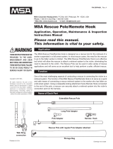
Figure 1 - Parts Identication
Label
Carabiner
Bag
Rescue Ladder
Hanging
Plate
Bracket

2
1.0 aPPlIcatIons
1.1 PURPOSE: The DBI-SALA Rescue Ladder system is
designed for rescuing fall victims. It can be used to climb
to the victim and administer assistance. It can also be
presented to the victim to allow them to climb up or down
the ladder to safety.
IMPortant: The maximum working load for the Rescue Ladder
is one person, combined weight (person, clothes, tools, etc.) not
exceeding 310 lbs (141 kg).
warnIng: Where conditions of use permit, the Rescue Ladder user
(rescuer, victim, etc.) should be secured by a secondary fall protection
system.
1.2 LIMITATIONS: The following application limitations must
be recognized and considered before using this product:
A. CORROSION: Do not leave this equipment for long
periods in environments where corrosion of metal parts
could take place as a result of vapors rising into the
atmosphere from organic materials. Caution should be
exercised when working around sewage or fertilizer
because of their high concentration of ammonia, which
is very corrosive. Use near sea water or other corrosive
environments may require more frequent inspections or
servicing to assure corrosion damage is not affecting the
performance of the product.
B. CHEMICAL HAZARDS: Solutions containing acids,
alkali or other caustic chemicals, particularly at elevated
temperatures, may damage the Rescue Ladder. When
working with such chemicals, frequent inspection of
the entire Rescue Ladder must be completed. Consult
Capital Safety if doubt exists concerning using this
equipment around chemical hazards.
C. HEAT: In general, the Rescue Ladder is not intended
for use in environments where incendiary sparking
could cause an explosion or re. Use of this equipment
is prohibited where there exists the possibility of the
ladder coming into contact with power lines, live cables,
etc. Consult the manufacturer for special applications
of this equipment. Do not use where air temperatures
exceed 200° F (93°C) or where the ladder may come
into contact with material that is above 150° F (65°C).

3
D. CAPACITY: The Rescue Ladder is designed for use by
one person with a combined weight (person, clothing,
tools, etc.) of 310 lbs (141 kg) maximum. At no time
shall more than one person be on the ladder.
E. TRAINING: This equipment is intended to be installed
and used by persons who have been properly trained in
its correct application and use.
note: Other hazards may exist. Contact Capital Safety with any
concerns regarding your intended use of the Rescue Ladder.
IMPortant: Refer to applicable local, state and federal (OSHA)
requirements governing this equipment for additional information
regarding personal fall arrest systems and associated system
components.
warnIng: Manufacturer’s instructions must be followed for proper
system use and maintenance of this product. Alterations or misuse of
this system or failure to follow instructions may result in serious injury
or death.
2.0 systeM reQUIreMents
2.1 COMPATIBILITY OF COMPONENTS: The Rescue Ladder
system is designed for use only with DBI-SALA approved
components. Substitutions or replacements made with
non-approved components and subsystems may jeopardize
compatibility of equipment and may affect the safety and
reliability of the complete system. Contact Capital Safety if
you have any questions about compatibility.
2.2 COMPATIBILITY OF CONNECTORS: Connectors are
considered to be compatible with connecting elements
when they have been designed to work together in such
a way that their sizes and shapes do not cause their gate
mechanisms to inadvertently open regardless of how they
become oriented. Connectors (hooks, carabiners, and
D-rings) must be capable of supporting at least 5,000
lbs. (22 kN). Connectors must be compatible with the
anchorage or other system components. See Figures 4 and
5 and section 3.4 for additional information on anchorage
connections. Do not use equipment that is not compatible.
Non-compatible connectors may unintentionally disengage
(see Figure 2). Connectors must be compatible in size,
shape, and strength. Self locking snap hooks and carabiners
are required by ANSI Z359.1 and OSHA.

4
Figure 2 - Unintentional Disengagement (Rollout)
If the connecting element to which a snap hook (shown) or
carabiner attaches is undersized or irregular in shape, a situa-
tion could occur where the connecting element applies a force
to the gate of the snap hook or carabiner. This force may cause
the gate (of either a self-locking or a non-locking snap hook)
to open, allowing the snap hook or carabiner to disengage from
the connecting point.
Small ring or
other non-
compatibly
shaped element
1.Force is applied to the
snap hook.
2. The gate presses
against the
connecting ring
3. The gate opens
allowing the snap
hook to slip off
2.3 MAKING CONNECTIONS: Only use self-locking snap hooks
and carabiners with this equipment. Only use connectors
that are suitable to each application. Ensure all connections
are compatible in size, shape and strength. Do not use
equipment that is not compatible. Ensure all connectors are
fully closed and locked.
DBI-SALA connectors (snap hooks and carabiners) are
designed to be used only as specied in each product’s
user’s instructions. See Figure 3 for inappropriate
connections. DBI-SALA snap hooks and carabiners should
not be connected:
A. To a D-ring to which another connector is attached.
B. In a manner that would result in a load on the gate.
note: Large throat opening snap hooks should not be connected
to standard size D-rings or similar objects which will result in a load
on the gate if the hook or D-ring twists or rotates. Large throat snap
hooks are designed for use on xed structural elements such as rebar
or cross members that are not shaped in a way that can capture the
gate of the hook.

5
Figure 3 - Inappropriate Connections
C. In a false engagement, where features that protrude
from the snap hook or carabiner catch on the anchor and
without visual conrmation seems to be fully engaged to
the anchor point.
D. To each other.
E. Directly to webbing or rope lanyard or tie-back (unless
the manufacturer’s instructions for both the lanyard and
connector specically allow such a connection).
F. To any object which is shaped or dimensioned such that
the snap hook or carabiner will not close and lock, or
that roll-out could occur.
2.4 ANCHORAGE STRENGTH: Anchorages selected for the
Rescue Ladder system shall have a strength capable of
sustaining static loads applied in the directions permitted by
the system of at least 3,000 lbs (13.3 kN).

6
3.0 oPeratIon and Use
warnIng: Do not alter or intentionally misuse this equipment.
Consult Capital Safety when using this equipment in combination with
components or subsystems other than those described in this manual.
Some subsystem and component combinations may interfere with the
operation of this equipment. Use caution when using this equipment
around moving machinery, electrical hazards, chemical hazards, sharp
edges, and abrasive surfaces.
warnIng: Consult your doctor if there is any reason to doubt your
tness to safely absorb the shock from a fall arrest or suspension.
Age and tness seriously affect a worker’s ability to withstand falls.
Pregnant women or minors must not use DBI-SALA rescue devices
unless in an emergency situation.
3.1 BEFORE EACH USE: Before each use of this equipment,
carefully inspect it to assure that it is in serviceable
condition. Check for worn or damaged parts. Inspect the
web material, for cuts, fraying, burns, etc. Refer to section
5.0 for further inspection details. Do not use if inspection
reveals an unsafe condition.
3.2 PLANNING: Plan your rescue system and how it will be
used before starting your work. Take into consideration
factors that affect your safety before, during, and after
a fall. The following list gives some important points to
consider when planning your system:
A. ANCHORAGE: Select an anchorage point that is rigid
and capable of supporting 3,000 lbs. (13.3 kN). See
Figures 4 and section 2.3. The anchorage location
must be carefully selected to reduce possible swing fall
hazards and to avoid striking an object during a fall.
B. SHARP EDGES: Avoid working where the web will be in
contact with or abrade against sharp edges. If working
with this equipment around sharp edges is unavoidable,
provide protection by using a heavy pad over the
exposed sharp edge.
3.3 MAKING CONNECTIONS: Self locking snap hooks or self
locking and self closing gate carabiners must be used to
reduce the possibility of roll-out when making connections.
See sections 2.2 and 2.3. Do not use hooks or connectors
that will not completely close over the attachment object.
Do not use non-locking snap hooks. Always follow the
manufacturer’s instructions supplied with each system
component.

7
3.4 SETUP AND INSTALLATION: The anchorage point for the
Rescue Ladder system must be capable of supporting 3,000
lbs (13.3 kN). The Rescue Ladder may be secured to the
anchorage by any of the following methods:
Connect the three carabiners on the ladder directly •
to the anchorage. Each carabiner should have its own
connection point (hole).
Connect the ladder to the anchorage with a Hanging Plate •
Bracket (PN 8516316). Figure 4 illustrates connection to
the anchorage point with a Hanging Plate Bracket. See
Section 2.2 for connector compatibility recommendations.
IMPortant: An independent fall protection system is required by
law (OSHA). Do not connect fall protection equipment directly to
the Rescue Ladder. Fall protection systems must be connected to an
independent anchor with a minimum tensile strength of 5,000 lbs.
(measured in direction of possible fall). Refer to ANSI Z359.1, ANSI
A10.14, applicable local, state, and federal (OSHA) requirements and
Capital Safety for additional information on independent fall protection
systems.
warnIng: Read and follow manufacturer’s instructions for
associated equipment (full body harness, etc.) used with this system.
3.5 CONNECTING MULTIPLE LADDERS: Multiple Rescue
Ladders can be connected together to accommodate
distances that exceed the length of a single ladder (see
Figure 5).
4.0 traInIng
4.1 It is the responsibility of the user to assure they are familiar
with these instructions, and are trained in the correct care
and use of this equipment. Users must also be aware of
the operating characteristics, application limits, and the
consequences of improper use of this equipment.
IMPortant: Training must be conducted without exposing the
trainee to a fall hazard. Training should be repeated on a periodic
basis

8
Figure 4 - Hanging Plate Bracket
Carabiner -
Connect to
anchorage capable
of supporting
3,000 lbs (13.3 kN)
Hanging
Plate
Bracket
Carabiner
Rescue
Ladder

9
Figure 5 - Connecting Multiple Rescue Ladders
Ladder 1
Ladder 2
Carabiner
Short Leg
Long Leg

10
5.0 InsPectIon
5.1 FREQUENCY:
Before Each Use: • Visually inspect per steps listed in
sections 5.2 and 5.3.
Monthly: • A formal inspection of the Rescue Ladder
system should be done by a competent person other
than the user. See sections 5.2 and 5.3 for guidelines.
Record the results in the Inspection and Maintenance Log
in section 9.0.
Annually: • It is recommended that the Rescue Ladder
system be serviced by a factory authorized service center
or the manufacturer. Extreme working conditions may
indicate the necessity to increase the frequency. Annual
servicing shall include, but not be limited to, an intensive
inspection and cleaning of all internal and external
components. Failure to provide proper service may
considerably shorten product life and could endanger
performance. See section 8.0.
IMPortant: Extreme working conditions (harsh environment,
prolonged use, etc.) may require increasing the frequency of
inspections.
5.2 INSPECTION STEPS: Inspect the ladder(s), bracket, and
carabiners that comprise the Rescue Ladder system per the
following instructions:
Step 1. Inspect the ladder(s):
Inspect webbing: Material must be free of •
frayed, cut, or broken bers. Check for tears,
abrasions, mold, burns, or discoloration.
Inspect stitching: Check for pulled or cut •
stitches. Broken stitches may indicate the ladder
has been impact loaded and must be removed
from service.
Inspect labels: All labels (illustrated in Section •
8.0) must be present and fully legible.
Step 2. Inspect the bracket:
Inspect for bent or damaged parts:•
Make certain the frame is not damaged or •
distorted.
Inspect ferrules for cracks or damage.•

11
Inspect wire rope for cuts, kinks, broken wires, •
bird-caging, corrosion, welding splatter, chemical
contact, or severe abrasion.
Inspect the identication and warning label •
(illustrated in Section 8.0). The label must be
present and fully legible.
Step 3. Inspect the carabiners:
Inspect all carabiners for bent or damaged parts.•
Ensure the gate on each carabiner closes •
properly and remains locked.
Step 4. Inspect any additional system components or
subsystems according to the manufacturer’s
instructions.
note: Record the inspection date and results in the
Inspection and Maintenance Log (see Section 9.0).
5.3 DEFECTS: If inspection or operation reveals a defective
condition, remove the defective component from service
immediately and contact an authorized service center for
repair.
note: Only Capital Safety or parties authorized in writing may
make repairs to this equipment.
5.4 PRODUCT LIFE: The functional life of the DBI-SALA
Rescue Ladder system is determined by work conditions
and maintenance. As long as the product passes inspection
criteria, it may remain in service.
6.0 MaIntenance - serVIce - storage
6.1 CLEANING - BRACKETS & CARABINERS: Periodically
clean brackets and carabiners using water and a mild soap
detergent solution.
6.2 CLEANING - RESCUE LADDER: Clean the ladder with a
mild soap solution. Do not use bleach or bleach solution.
Wipe off hardware with a clean, dry cloth, and hang to air
dry. Do not force dry with heat. An excessive buildup of dirt,
paint, etc. may prevent the ladder from working properly,
and severe cases degrade the webbing to a point where it
weakens and should be removed from service. Additional
information on cleaning is available from Capital Safety. If
you have questions concerning the condition of your safety
ladder, or have any doubt about putting it into service,
contact Capital Safety.

12
6.3 ADDITIONAL MAINTENANCE AND SERVICE: Additional
maintenance and service procedures must be completed
by a factory authorized service center. Do not attempt to
disassemble the unit.
6.4 STORAGE: Store the Rescue Ladder system in a cool
dry, clean environment out of direct sunlight. Avoid areas
where chemical vapors may exist. Thoroughly inspected the
Rescue Ladder system after extended storage.
7.0 sPecIFIcatIons
Ladder: Polyester Web
Polyester Thread Stitching
Bracket: Black Anodized Aluminum
Galvanized Wire Rope - 3/16 in (5 mm) dia. - 7 x 19 construction
Carabiner: Plated Alloy Steel
8.0 laBelIng
The following labels should be securely attached to the Rescue
Ladder and Bracket:
Rescue Ladder Label Bracket Label
Front Back

13
9.0 InsPectIon and MaIntenance log
SERIAL NUMBER: ____________________________________
MODEL NUMBER: _____________________________________
DATE PURCHASED: ___________DATE FIRST USED: _______
INSPECTION
DATE
INSPECTION
ITEMS NOTED
CORRECTIVE
ACTION
MAINTENANCE
PERFORMED
Approved By:
Approved By:
Approved By:
Approved By:
Approved By:
Approved By:
Approved By:
Approved By:
Approved By:
Approved By:
Approved By:
Approved By:
Approved By:
Approved By:

WARRANTY
Equipment offered by DBI-SALA is warranted against factory defects
in workmanship and materials for a period of two years from date of
installation or use by the owner, provided that this period shall not ex-
ceed two years from date of shipment. Upon notice in writing, DBI-SALA
will promptly repair or replace all defective items. DBI-SALA reserves
the right to elect to have any defective item returned to its plant for
inspection before making a repair or replacement. This warranty does
not cover equipment damages resulting from abuse, damage in transit,
or other damage beyond the control of DBI-SALA. This warranty ap-
plies only to the original purchaser and is the only one applicable to our
products, and is in lieu of all other warranties, expressed or implied.
CSG USA
3833 Sala Way
Red Wing, MN 55066-5005
Toll Free: 800.328.6146
Phone: 651.388.8282
Fax: 651.388.5065
solutions@capitalsafety.com
CSG Canada Ltd.
260 Export Boulevard
Mississauga, Ontario L5S 1Y9
Toll Free: 800.387.7484
Phone: 905.795.9333
Fax: 905.795.8777
sales.ca@capitalsafety.com
www.capitalsafety.com
Certificate No. FM 39709
ISO
9001
/