Page is loading ...

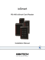
P345MTR and P345KPMTR
Multi-Technology
Installation Manual
125 KHz and 13.56 MHz Readers
DN1870-0905

DN1870-0905
ii
P345MTR and P345KPMTR Readers Installation Manual
Table of Contents
Introduction ...................................................................................5
Features ........................................................................................6
Mounting .......................................................................................6
Installation Considerations ............................................................8
Wiring ............................................................................................9
Installation Notes .........................................................................10
Troubleshooting ..........................................................................11
Technical Specifications ..............................................................12

DN1870-0905
1
P345MTR and P345KPMTR Readers Installation Manual
Copyright Information
Copyright © 2009 Tyco International Ltd. and its Respective Companies. All Rights
Reserved. All specifications were current as of publication date and are subject to
change without notice. Kantech and the Kantech logo are trademarks of Tyco
International Ltd. and its Respective Companies.
Technical Support
For technical assistance with the P345MTR, P345KPMTR and other Kantech
products, contact technical support, Monday to Friday.
See the following table for the technical support phone numbers.
Country
/Region
Phone Numbers
Support
Hours
Email
North America Toll Free +888 222 1560 (GMT -05:00)
US and
Canada
Direct: +450 444 2030
Fax: +450 444 2029
8:00 to
20:00
Latin America (GMT -03:00)
Argentina
Direct: +5411 4717 2929
+5411 4717 1320
+5411 4717 5525
Fax: +5411 4717 1060
9:00 to
18:00
Asia (GMT +08:00)
Singapore
Direct: +65 6319 9820
Fax: +65 6319 9821
Direct: +65 6389 8297
Fax: +65 6389 8292
8:30 to
18:00

DN1870-0905
2
FCC Digital Device Limitations
This device complies with Part 15 of the FCC rules Class A. Operation is subject
to the following two conditions: (1) this device may not cause harmful
interference, and (2) this device must accept any interference received including
interference that may cause undesired operation. This class A digital apparatus
meets all requirements of the Canadian Interference Causing Equipment
Regulations. The P345MTR and P345KPMTR readers are also compliant with
EN55022:1998, amendment 1:1995, Class A.
Europe Toll Free +800 CALL TYCO / +800 2255 8926 (GMT +01:00)
Bahrain +800 04127
8:00 to
18:00
France +33 04 72 79 14 83
Greece +00 800 31 22 94 53
Russia +8 10 800 2052 1031
Spain +900 10 19 45
Turkey +00 800 31 92 30 37
United
Arab
Emirates
+800 0 31 0 7123
United
Kingdom
+44 08701 ADT SUP /
44 08701 238 787
Direct: +31 475 352 722
Fax: +31 475 352 725
Country
/Region
Phone Numbers
Support
Hours
Email

DN1870-0905
3
P345MTR and P345KPMTR Readers Installation Manual
In order to maintain compliance with FCC regulations, shielded cables must be used
with this equipment. Operation with non-approved equipment or unshielded cables
is likely to result in interference to radio and television reception.
CAUTION: Changes or modifications not expressly approved by Kantech for
compliance could void the user’s authority to operate this equipment.
UL Standards Compliance
The products are intended for use with UL 294 Listed access control units where
compatibility with the reader(s) is indicated in the Listed control unit's installation
instructions.
To be used with UL Listed Access Control Units as indicated in the control unit’s
installation instructions.
For this product, the HID KSF (Kantech Secure Format) and ioProx Kantech XSF
have not been evaluated by UL.
UL has not evaluated the RS-485 Output of this reader.
Tamper Circuit Electrical Rating for UL Installations (Pins 11 & 12) is 100 mA at
30 VDC.
CE Compliance
• EN50364: Limitation of human exposure to electromagnetic fields from
devices operating in the frequency range 0 Hz to 10 GHz, used in
Electronic Article Surveillance (EAS), Radio Frequency Identification
(RFID) and similar applications.
• EN60950-1: Information technology equipment. Safety. General
requirements.
• ETSI EN300 330-1: Electromagnetic compatibility and Radio spectrum
Matters (ERM); Short Range Devices (SRD); Radio equipment in the
frequency range 9 kHz to 25 MHz and inductive loop systems in the
frequency range 9 kHz to 30 MHz; Part 1: Technical characteristics and
test methods.

DN1870-0905
4
• ETSI EN300 330-2: Electromagnetic Compatibility and Radio
Spectrum Matters (ERM); Short Range Devices (SRD); Radio
Equipment in the Frequency Range 9 kHz to 25 MHz and Inductive
Loop Systems in the Frequency Range 9 kHz to 30 MHz; Part 2:
Harmonized EN under Article 3.2 of the R&TTE Directive.
• ETSI EN301 489-1: Electromagnetic compatibility and Radio
spectrum Matters (ERM); ElectroMagnetic Compatibility (EMC)
standard for radio equipment and services; Part 1: Common technical
requirements.
• ETSI EN301 489-3: Electromagnetic Compatibility and Radio
Spectrum Matters (ERM); ElectroMagnetic Compatibility (EMC)
Standard for Radio Equipment and Services; Part 3: Specific
Conditions for Short-Range Devices (SRD) Operating on Frequencies
between 9 KHz and 40 GHz.
RoHS (Restriction on Hazardous Substances)
This standard restricts the use of the following substances: Lead, cadmium,
mercury, chromium IV, polybrominated biphenyl (PBB), and polybrominated
diphenyl ether (PBDE) in electrical and electronic equipment by no later than
July 1, 2006.
WEEE (Waste Electrical and Electronic
Equipment)
This regulation is used for Waste Electrical and Electronic Equipment, and
addresses the disposal and the environmental handling of these products.

DN1870-0905
5
P345MTR and P345KPMTR Readers Installation Manual
Introduction
The P345MTR Contactless readers will read Prox and Smart Cards at frequencies
of both 125 kHz and 13.56 MHz. The reading capability includes, for Smart Cards,
both unencrypted serial numbers and encrypted MIFARE® programmed sectors.
Refer to Table 1 for a complete list of compatible standards and data.
The P345KPMTR reader has a built-in keypad with 12 keys, including CMD/ENTER
and CE (Clear Entry). The reader outputs the PIN code in the 8-bit burst Wiegand. It
also has the ability to read and verify the PIN on a Smart Card. This feature is
enabled with the use of program cards. Please contact Kantech for more information
on the PIN-on-Card function.
Table 1: Compatible Credential Formats
ioProx Kantech XSF CASI-RUSCO® Prox Lite
HID KSF (Kantech Secure Format) ISO 14443A (MIFARE®) Sector
HID® 26 Bit ISO 14443B Serial Number
HID® Corporate 1000 ISO 15693 Serial Number
HID® 36 Bit Wiegand MIFARE® Sector
HID® 37 Bit Wiegand DESFire® Serial Number
Other HID pass through formats iCLASS® Serial Number
Deister Prox SmartFrame® Others - Future Expansion

DN1870-0905
6
Features
• Universal compatibility with most 125 kHz Prox (including all ioProx XSF and
HID® Prox formats), all ISO 15693, and ISO 14443A credentials (badges, disk
tags and key fobs). Reads both 125 kHz and 13.56 MHz credentials in the
same reader.
• Electrical protection (reverse polarity diode protection on power lines).
• Data lines: high-speed transient voltage suppressor diodes.
• IP65-rated sealed electronics for deployment in both interior and exterior
environments.
• Integrated reader tamper protection.
Mounting
Mount the single-gang backplate (with tamper magnet installed) onto the wall.
Figure 1: P345MTR Reader Backplate with Tamper Switch Magnet
Note: Mounting holes fit standard U.S. single-width electrical box and standard
European (EMEA) electrical box hole patterns.
Mount the reader module directly to the backplate and then snap the front cover
in place as indicated in Figure 2.

DN1870-0905
7
P345MTR and P345KPMTR Readers Installation Manual
Figure 2: Mounting Assembly with Isolation Spacer (Optional)
Please note that Figure 2 shows the P345MTR reader and cover plate. Although the
P345KPMTR keypad reader and front cover plate differ, the mounting assembly is
the same as the P345MTR.

DN1870-0905
8
Installation Considerations
The P345-SPACER isolation spacer may be used to improve the read range
distance when mounting the reader to a metal surface. To optimize reader
range, use the number of backplates as indicated in Table 2. Use of Isolation
Spacers is optional and not required for non-metal mounting surfaces.
Table 2: Isolation Spacer Recommendation for Mounting on Metal
Installation of two P345MTR readers side-by-side and back-to-
back
Read range is not affected if the center-to-center distance between two readers
is greater than or equal to four (4) inches (101.6 mm). Two readers can
simultaneously read the same badge or tag if the distance between the two
readers is less than 4 inches, center-to-center. If the distance between the two
readers is less than four inches, field interference between the two readers may
result in a double-badge read.
Note: If two readers are being placed back-to-back on a wall less than 4 inches
thick, maximum performance can be achieved by using a metal separation
plate and then using isolation spacers as necessary.
Distance Reading Distance
No metal plate 100%
4.5 cm 100%
2.7 cm (3 tamper plates) 85%
1.8 cm (2 tamper plates) 70%
0.9 cm (1 tamper plate) 50%
0 cm 10%

DN1870-0905
9
P345MTR and P345KPMTR Readers Installation Manual
Wiring
P345MTR models have twelve terminals as noted in Table 3. The terminal strip is
removable for easy installation and wiring. When attaching wires to the connector,
strip off only the minimum insulation required (approx. 1/8'') and push the wire into
the connector until the insulation is flush or inside the connector body. This is
particularly critical for outdoor readers. While the reader itself is designed and
protected to IP65 standards, the cable wires can potentially corrode and short
together if not carefully mounted and tightly fastened in the connector body.
Table 3: Connector Pins
Table 4 indicates maximum wiring distances per Wiegand standard with the three
most common gauges of cable.
Table 4: Maximum Cable Distance per Wire Gauge
Pin Description Pin Description
1 Buzzer 7 External Green LED Control
2 Ground 8 External Red LED Control
3 Power (9.4 to 16 VDC) 9 A - RS-485 - Used for Flash Upgrade
4 D1 Wiegand 10 B - RS-485 - Used for Flash Upgrade
5 D0 Wiegand 11 Tamper (Normally Closed)
6 Reserved for Future Use 12 Tamper (Normally Closed)
Wire Gauge 18 AWG 20AWG 22 AWG
Cable Distance
500 feet
(152 meters)
300 feet
(91 meters)
200 feet
(61 meters)

DN1870-0905
10
Installation Notes
Unless otherwise specified in this manual, please follow these guidelines:
Important: Use only shielded cabling for connections.
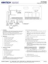
1 Connect the reader to the controller. See Figure 3 for connecting the reader to
a Kantech controller.
Note: You can use a local power supply for the reader. If so, don’t connect the power
supply from the controller to the reader. The ground line of the local power
supply must be connected to the power supply of the controller.
Figure 3: Wiring Examples to Kantech Controllers
2 The unit needs to be operated with a power source with limited power
consumption according to EN 60950-1 (2003) paragraph 2.5.
3 Use of a pull-up resistor may be required by some controllers others than
Kantech controllers. Consult your controller manual.
4 For tamper wiring, connect Pins 11 and 12 to a
normally closed supervised input.

DN1870-0905
11
P345MTR and P345KPMTR Readers Installation Manual
Troubleshooting
If the operation of a component is in doubt, substitute a known good component and
retry the system. Always verify wiring against the provided wiring information before
powering up the reader.
Table 5: Error Conditions and Possible Solutions
Condition Possible Solutions
None of the LEDs are on.
Check the following:
Power connections to the reader.
Reader supply voltage at connector pin 3 and that
the ground connection pin 2 is secure and well
connected.
The door does not open
and the green LED does
not light when a qualified
credential is presented.
Verify that the door strike and the green LED are wired
correctly. Verify that the access credential has been
entered and that the reader has been properly
configured in the host system.
The green LED does not
light but the door strike
unlocks the door when a
valid credential is
presented.
Verify that the door strike is wired correctly. Refer to
the appropriate wiring diagram in your controller
manual. Disconnect the wire from pin 7 (green LED)
and connect pin 7 to pin 2 (ground). If the green LED
is now on, the reader is good and the connection to
the reader is defective. If the green LED does not light,
replace the reader.

DN1870-0905
12
Technical Specifications
Cable Recommendations
4 core (minimum), shielded,
22 AWG (minimum) cable
Connectors 12 position, 3.5 mm Screw Terminals - Plug-In
Certifications FCC Part 15, CE and UL 294
Open Standards
Compliance
ISO 14443A
ISO 14443B (Depending on specific
implementation)
ISO 15693 (including some partially compliant
credentials)
Other Standards
Compliance
Deister SmartFrame® in both 125 kHz and 13.56
MHz implementations
HID Prox at 125 kHz (All Formats)
HID KSF (Kantech Secure Format)
ioProx Kantech XSF
PIN Code Entry Keys
(Model P345KPMTR only)
Twelve PIN code entry keys 0-9, Command/Enter,
and CE (Clear Entry)
Standard Color Black
Dimensions with backplate
(height / width / depth)
4.37 x 3.31 x 1.10 in
(11.09 x 8.41 x 2.79 cm)
Power Supply
Rated Voltage: 9.4 to 16 VDC, 125 mA maximum
current
Environments For both Indoor and Outdoor Use
Humidity 5 to 90% (non-condensing)
Operating Temperature -31°F to 151°F (-35°C to 67°C)
Index of Protection IP 65 (IEC 529)

DN1870-0905
13
P345MTR and P345KPMTR Readers Installation Manual
Read Range
1 to 5 in. (2.5 to 12.7 cm) depending on credential
technology and environment.
Note: Read range for credentials of identical
technologies may vary greatly depending on the
tuning and antenna structure of each individual
credential.
Standard Wiegand Output
including
ID Pass-Through Option
Serial Number Read
Fixed Wiegand bit stream option
SmartFrame® encrypted MIFARE Sector read and
conversion to Wiegand. Consult your Kantech
representative for available reconfiguration cards
for your reader.
8-bit burst Wiegand PIN code (P345KPMTR only)
PIN-on-card featured (P345KPMTR only)
Upgrade
(Future Use)
Complete upgrade capability using RS-485 port for
reflashing of internal ROM.

/