Page is loading ...

WARNING: This manual contains information on limitations regarding product use
and function and information on the limitations as to liability of the manufacturer.
The entire manual should be carefully read.
KT-100™ Door Controller
Installation Manual
InOut Systems - Access Control and Accessories
A division of Kantech Systems
DN5073-0205

Products names are trademarks or registered
trademarks of their owners.
No part of this publication may be reproduced in
any form without permission from Kantech
Systems, Inc.
IInOut Systems
Tel: +1(978) 731-6252 •
Toll Free: US & Canada: 1 888 222-1560 •
Fax: +1(978) 731-7759
Sales: Tel: +1(905) 706-3000 • Toll free: 1 888 888-7838
Web Site: www.inoutsystems.com
E-mails: sales@inoutsystems.com /
techlink@tycoint.com
© 2002, InOut Systems, a division of Kantech Systems.
All rights reserved.
Specifications may be modified without notice.
™ Trademarks of Kantech Systems.

Table of contents
Section 1: KT-100 Features 3
Section 2: Mounting and Wiring the KT-100 Door
Controller 5
Step 1•Unpacking the KT-100 ..............................................5
Step 2•Selecting a Mounting Location .................................5
Step 3•Installing the Power Supply ......................................5
Step 4•Installing the KT-100 Unit ........................................5
Step 5•Connecting the Door Locking Device ......................6
Step 6•Hooking up Inputs .....................................................6
Step 7•Connecting Readers and Keypads .............................7
Step 8•Connecting Control Relay Outputs ...........................7
Step 9•Connecting the Tamper Switch .................................7
Step 10•Connecting the KT-100 to the RS-485 Bus ............8
Section 3: Appendix 9
Typical KT-100 Wiring Diagram ............................... 9
KT-100 Compliance Notices ................................... 10
Troubleshooting Communication Problems ........ 10
KT-100 Controller Maintenance ............................. 11
Bi-annual test for battery ............................................11
Annual test for emergency lithium battery .................11
Mounting the KT-PC4204 ....................................... 11
Using the KT-100 with an external alarm panel ... 12

6

KT-100 Installation Manual
3
Section 1: KT-100 Features
The KT-100 Door Controller contains all the intelligence and
necessary inputs/outputs to manage one door; it is also easily
linked to a network controlling up to 32 doors.
The KT-100 Door Controller features include:
Speed selection. The KT-100 automatically detects the loop
communication speed as set at the system workstation.
Trouble reporting. The KT-100 constantly supervises
power supply conditions and reports “Low power” status to the
system. The power output is protected against short-circuits and
surges by a self-resetting PTC. The locking device is supervised
for short to ground or open circuits. It also monitors all the
equipment for any failure or tampering. Any abnormal
condition is reported to the software.
Downloadable firmware. The firmware program is
stored in the controller’s flash memory; it can be easily updated
from the system’s workstation without changing the memory
chips.
Integration with a client alarm system. The KT-100
Controller allows the ability to arm/disarm any client alarm
system. In addition, interfacing with an external alarm system
allows the installer to assign the appropriate user permission to
arm or disarm the external alarm system. Optionally, adding a
keypad will increase the security as cardholders will be required
to enter a valid code in addition to presenting a valid card at the
door reader. For details about using the KT-100 Controller to
interface another alarm panel, refer to “Using the KT-100 with
an external alarm panel” on page 12.
Technical Specifications
Input power 9.5 to 14 VDC / 50mA + accessories (Max. 750 mA)
Dimensions (H•W•D) 11.4 cm x 7.0 cm x 3 cm (4.5”; 2.75”; 1.25”), mounted in a standard single gang electri-
cal box without any additional enclosure
Weight 110 g (0.22 lbs)
Operating temperatures / Humidity range From 20 C to 400 C (350 F to1100 F) / 0-95% (non-condensing)
Reader types Wiegand, proximity, bar code, magnetic, integrated keypad and others
Control relay outputs 2 relay outputs, 12VDC, 25mA max/each. Open collector to ground (use form C relays such as
Kantech/KT-RM1 if needed)
2 control relay outputs, 30VAC/DC, 50mA (max) each. Two Opto-isolated contacts per relay
Monitored input zones 4 monitored input zones, NO/NC, with or without end of line resistors
Points maximum wiring 600 meters (2,000 feet) - (AWG #22)
Door strike output 1 form C output, 12VDC, 250 mA max, supervised
Auxiliary outputs (LED, BUZ) 2 outputs, open NPN collector for door access and status 25mA max, 12 DC each
Reader power output 5VDC @ 150mA protected
Communication port RS-485
Communication speed From 1200 to 115,200 baud (automatic detection)
Reader communication interface ANSI, SIA, ABA clock and data, Wiegand 5 conductor
Flash memory 64 K
RAM memory 128 K
Backup battery Lithium battery, up to 10 years retention (data and RTC operation)
Network autonomy Distributed data and processing
Certifications / Listing FCC Part 15, Class B

4
KT-100 Installation Manual

KT-100 Installation Manual
5
Section 2: Mounting and Wiring the KT-100
Door Controller
Step 1•Unpacking the KT-100
The KT-100 Controller has been designed to be mounted on a
wall in a single gang electrical box without any additional
enclosure.
Before installing the KT-100 Door Controller:
1. Unpack the KT-100 Controller package. The following
items are required to install the KT-100:
◗KT-100 Controller with accessory kit (included),
◗PC4204 DC Power Supply with battery backup
(suggested, not included),
◗AC transformer; Input: 120 or 230 VAC; Output: 16
VAC, 40VA, class 2 (not included)
◗One 12-volt lead-acid battery 7A/h (not included)
◗Ground clamp (not included).
2. Verify the content for any missing item/part or damaged
component. Any missing or damaged item should be
reported immediately.
Step 2•Selecting a Mounting Location
The KT-100 Door Controller should be accessible for ease of
installation and maintenance.
Select an ideal indoor location using the
following guidelines:
◗Stay away from electrical or communication
devices: controllers must be located at a minimum
distance of 2 m (6 feet) from any high voltage
equipment or wiring (> 230 Volts) and from
electrical equipment susceptible of generating
electrical interference, at a minimum distance of 1
meter (3 feet) from telephone equipment or lines,
and at a minimum of 8 meters (25 feet) from any
transmitting equipment.
◗The controller should be mounted indoors in a
secure location providing normal temperature and
humidity levels.
◗Controllers should be located close to the controlled
door.
◗Physical access, using keys, on controlled door must
be provided so that the KT-100 can easily be
accessed for servicing in case of malfunctions.
Step 3•Installing the Power Supply
The suggested power supply is the KT-PC4204.
The power supply cabinet (Kantech part no. KT-4051CAB) is
large enough to accommodate the battery backup supply and the
necessary wiring connections for most applications. EMT
(Electrical Metallic Tubing) conduit knockouts are provided in
2.2 cm (7/8”) on all sides of the cabinet.
NOTE: Power should only be applied to the unit when all con-
nections are completed and tested.
For details on installing the KT-PC4204, refer to “Mounting the
KT-PC4204” on page 11.
NOTE: If you are installing another type of power supply, refer
to the manufacturer’s instruction.
Step 4•Installing the KT-100 Unit
The following diagram illustrates a typical door
layout:
Door handle. The outside door handle (or knob) should be
permanently locked. The access controller should always be the
one which unlocks the door by releasing the electric lock. The
inside door handle should be free (unlocked) to permit safe exit
in case of emergency. To prevent a door from being left
manually unlocked, make sure there are no lock/unlock buttons
on the inside doorknob.

6
KT-100 Installation Manual
Door closer. A standard hydraulic door closer is almost
mandatory to insure that the door closes automatically after an
entry and to prevent “door open too long” or “door left open”
alarms.
Door contact. When the door is locked, the access
controller supervises the door contact and will report a “door
forced open” alarm if the door is opened without the use of a
card. When the door is unlocked, the condition of the door
contact is still supervised but no alarms are generated.
Exit detector and exit button. The exit detector or
button will warn the system of the pending opening of a free
exit door by a user leaving the protected area.
Local door alarm. The local door alarm is integrated in the
IoProx Door Reader for outside and in the T-Rex for inside. It
provides audible indication of an abnormal condition. The most
common conditions to be reported locally are “door forced
open” and “door open too long” events.
Reader and keypad. A keypad only installation is
considered less secure than a reader only installation. Adding a
keypad to a reader significantly increases the level of security.
Step 5•Connecting the Door Locking Device
The lock NC, NO and +12VDC terminals are located on the top
left of the KT-100 Controller terminal strip.
The locking device output is controlled by the software
according to preset parameters for allowing access or unlocking
doors according to schedules and access levels.
The NO or NC output can operate DC powered locking devices
such as electromechanical strikes and can be configured to
operate in fail-safe or fail-secure modes (normal or reverse
action). The maximum permitted current is 250mA @ 12VDC
per output.
NOTE: Use 1K ohm end-of line resistor between +12VDC and
NC if not used. This resistor is already included in the box (KT-
100-ACC).
To connect the door locking device:
1. Connect the negative wire from the door strike to the NO
output and optionally, the door magnetic lock to the NC
output.
2. Connect the positive wire to the +12 VDC output.
WARNING!Controlled door locks may be governed by
regulatory bodies and should always be installed
according to local regulations. In most instances, there
are strict limitations to installing fail-secure devices
and fail-safe locking devices such as magnetic locks or
other similar locking devices on doors used as
emergency exits.
Step 6•Hooking up Inputs
The KT-100 has an on-board capability of monitoring 4 input
zones. Each input is supervised with or without end-of-line
resistors (5.6K ohm). The maximum distance of one line is 600
m (2,000 feet) with AWG#22 (Kantech part #CBL-R2).
By default, inputs 1-2 are reserved for the door contact and the
request to exit. The door contact is assigned to input 1 (Z1) and
the associated request-to-exit detector to input 2 (Z2). There is
no obligation to follow these rules but such a standard
convention makes it easier for servicing.
PWR OUT
12VDC LOCK
+-
500mA Max --
NO NC
DOOR LOCKING DEVICE
12 VOLTS DC 250 mA MAX.
Fail Safe if connected to NO,
Fail Secure if connected to NC.
ELECTRICAL MAG-LOCK
12 VOLTS DC 250 mA MAX.
If not used, connect a 1000 ohms
resistor between NC and +12V.

KT-100 Installation Manual
7
To connect inputs:
1. Connect devices between inputs Z1 to Z4 and COM.
2. Connect resistors (included with KT-100) for all inputs
5.6K ohm (if selected).
NOTE: Inputs can be defined with none or one end-of-line resis-
tor according to parameters defined in your EntraPass Special
Edition software.
Step 7•Connecting Readers and Keypads
The maximum allowable distance between the readers and the
KT-100 controller varies by reader type. Please consult the
reader manual for details.
WARNING! Connecting the red wire lead (or power
lead) of a 5VDC reader to the 12VDC terminal may
damage the reader. Refer to the reader installation
procedure for proper power connection. Up to 2
readers can be connected to a KT-100. They can be
installed on one door to control both entry and exit.
To connect the reader (entry and exit) refer to
the diagram below:
NOTE:
◗The 12 VDC auxiliary power can also be used to power
low current audible devices usually located at the
controlled door. Auxiliary outputs can be connected to
readers & local warning devices to be used for visual and
audible signals.
◗Auxiliary output “LED” provides visual feedback of
access operation; auxiliary output “BUZ” can activate
audible warning devices, such as T.REX, to signal door
alarms.
Step 8•Connecting Control Relay Outputs
The KT-100 provides two opto-isolated contacts (R1 & 2) and
two control outputs (R3 & 4). R1 & 2 can be used as either as
dry contacts.
◗R1 & R2: maximum voltage = 30 volts AC/DC;
maximum current = 100 mA total; (R1 & R2).
◗R3 & R4: maximum voltage = 12 volts DC;
maximum current (each relay) 25 mA
NOTE: Use a KT-RM1 (optional) to switch larger currents or
voltages or to supply a dry contact.
Step 9•Connecting the Tamper Switch
Optionally, a tamper switch may be installed on the unit to
detect unauthorized opening of the cabinet. For this purpose,
you may use the MUSB1 box for surface mount (Optional -
Kantech part # KT-100TAMP).
DOOR REX COM AUX AUX
INPUTS
Z1 Z2 Z3 Z4
Door Contact
T.REX
C1 NC1 NO1
-++ - TAMPER
POWER BUZZER
NC or NO Dry contact
Controller defined witho
u
End of Line Resistor
NC or NO Dry contact
Controller defined with
End of Line Resistor
Optional
5,6K End of Line Resistor
Additional Zone Inputs
(Z3 & Z4)
PWR OUT
12VDC
+-
Optional
5,6K End of Line Resistor
PWR OUT
12VDC PWR ENTRY EXIT
LED BUZ+5V WHT GR N WHT GRN
OUTPUTS
CARD READERS
+-
500mA Max
IOProx
Card Reader
IOProx
Card Reader
KT-100 EXIT READERENTRY READER
BLUE
BROWN
GREEN
WHITE
RED
BLACK
BLUE
BROWN
GREEN
WHITE
RED
BLACK
Relays Outputs
Internal
Equivalent
Circuits
R1 R2 R4R3
RELAYS
PWR IN
12VDC
PWR OUT
12VDC LOCK PWR ENTRY EXIT
LED BUZ
+- +5V WHT GRN WHT GRN
OUTPUTS
CARD READERS
750mA Max +-
500mA Max --
NO NC
RS-485
R1 R2 R3 R4 DOOR REX COM AUX AUX
INPUTSRELAYS
X+ X- Z1 Z2 Z3 Z4
12 volts DC
Relay
30 volts
AC/DC
Contact

8
KT-100 Installation Manual
The normally closed tamper switch is connected to an input. It
is recommended to choose an unused input (3 or 4) as tamper
input.
1. Install the KT-100TAMP tamper switch in the MUSB
box as illustrated below.
Step 10•Connecting the KT-100 to the RS-485 Bus
Controllers are linked together through their RS-485 screw
terminal. The maximum communication loop length with the
appropriate cable is 1.2 kilometers (4,000 feet) from the last
controller to the workstation.
NOTE: Do not connect several KT-100 controllers at a single
point or in a “Y” or “spider web networks”.
The RS-485 communication loop should be wired with Ethernet
Category 3 double twisted pair network cable (see cable
specifications Belden 1227A or equivalent). The RS-485 loop
can operate from 1,200 to 115,200 baud, under normal
conditions. The baud rate depends on the loop length and the
environment (Refer to Step 2 “Selecting a Mounting Location”
on page 5).
NOTE: Intermittent communication problems or erratic opera-
tion may require to slow down the network speed to 9,600 or
19,200 baud. Varying the network speed does not perceptibly
change the operation speed of the system. Usually, most instal-
lations should be set at 19,200 baud.
To link KT-100 Door Controllers:
1. Connect the RS-485 cable to X1+, X1- and GND.
◗If you are not using the USB-485 or VC-485:
connect a 120 ohm end-of-line resistor at the
interface of the first and last KT-100 (X- & X+);
◗When using the USB-485: connect a 120 ohm end-
of-line resistor on the last KT-100 only (X- & X+).
You do not need to connect the first KT-100 since
the USB-485 contains an end-of-line resistor.
NOTE: After you have completed all the necessary steps, you
may power the KT-100 by connecting the AC power and the bat-
tery.
R1 R2 R3 R4 DOOR REX COM AUX AUX
INPUTSRELAYS
Z1 Z2 Z3 Z4
TAMPER
SWITCH
MUSB
COVER
MUSB
BOTTOM
TAMPER
ARM
KT-100
RS-4 85
X+ X-
KT-100 #1
120 ohms
EOL res istor
RS-485
GND X- X+
USB485
WITH 120 OHMS
INTEGRATED EOL
RESISTOR
RS-485
X+ X-
KT-100 #2
RS-485
X+ X-
KT-100 #32
USB CABLE (3 METERS MAX) WORKSTATION
RS485 NETWORK: UNSHIELDED TWISTED PAIRS CABLE AWG #22 (1200 METERS MAX)

KT-100 Installation Manual
9
Section 3: Appendix
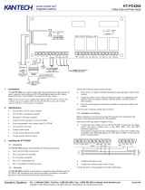
Typical KT-100 Wiring Diagram
PWR IN
12VDC
PWR OUT
12VDC LOCK PWR ENTRY EXIT
LED BUZ
+- +5V WHT GRN WHT GRN
OUTPUTS
KT-100
CARD READERS
750mA M ax +-
500mA M ax --
MADE IN CANADA
NO NC
RS-485
R1 R2 R3 R4 DOOR REX COM AU X AUX
INPUTSRELAYS
X+ X- Z1 Z2 Z3 Z4
ACCESS CONTROLLER
This device complies with Part 15 of the FCC rules.
Operation is subject to the following two conditions:
(1) This device may not cause harmful interference,
and (2) This device must accept any interference
received, including interference that may cause
undesired operation.
BLUE
BROWN
GREEN
WHITE
RED
BLACK
Optional Exit Reader
Door Locking Device
12 Volts DC 250 mA MAX.
Electrical Mag-Lock
12 Volts DC 250 mA MAX.
(IF NOT USED, CONNECT A 1000 OHMS
RESISTOR BETWEEN NC AND +12V)
IOProx Card
Reader
Entry Reader
Door Contact
WASHER
Sealed Acid-Lead
12 Volts Battery
7 A/h Maximum
KANTECH # KT-BD7-12
120/220 VOLTS 40VA
CLASS 2
(WIRE-IN)
Plug-in also available
Do not connect to receptacle
controlled by a switch
EARTH
GROUND
SCREW
CASE
4 Relays Module PC4204
NUT
RS485 Network
to others KT-100s
or
to PC Workstation
via USB/485 interface
T.REX
C1 NC 1 NO1
-++-TAMPER
POWER BUZZER
NC Dry contact
Controller defined without
End of Line resistor
NO Dry contact
Controller defined with
End of Line resistor
Opto-Isolated Contact
120 Volts AC/DC
100 mA Max. Load
Optional
End of Line resistor
Positive
Negative
12 Volts DC
Open-Collector
25 mA Max.
+12VDC

10
KT-100 Installation Manual
KT-100 Compliance Notices
This device complies with Part 15 of the FCC rules. Operation
is subject to the following two conditions:
◗(1) this device may not cause harmful interference,
and
◗ (2) this device must accept any interference
received including interference that may cause
undesired operation. This class B digital apparatus
meets all requirements of the Canadian Interference
Causing Equipment Regulations. The KT-100 is
also compliant with EN55022: 1994, amendment 1:
1995, Class B.
Troubleshooting Communication
Problems
The KT-100 default initialization is done at Kantech. The
following steps should only be done if:
◗You changed the software (e.g.: you were using
WinPass, then installed EntraPass) and there is no
communication,
◗You replaced an existing KT-100 by another one on
a loop,
To enable the default initialization (hard reset):
1. Disconnect the transformer and the battery from the
PC4204 power supply.
2. Remove all connections of Z1 (DOOR) and R3
terminals.
3. Place a jumper between the Z1 (DOOR) and R3
terminals.
4. Apply AC power to the transformer. The VITAL LED
should flash 4 times. This means that the controller is in
the initialization mode.
5. Disconnect the jumper. When the controller is
communicating with the PC, the VITAL LED will flash
3 beats at a time.
6. Reconnect the battery.
R1 R2 R3 R4 DOOR REX COM AUX AUX
INPUTSRELAYS
Z1 Z2 Z3 Z4
Jumper

KT-100 Installation Manual
11
KT-100 Controller Maintenance
To ensure the best operating conditions, it is highly
recommended to test the KT-100 controller by performing the
following tests.
Bi-annual test for battery
This test will ensure that if a power failure occurs, the battery
will be able to support normal operations. This test should be
performed twice a year.
1. Remove AC power from the power supply and power
the controller using the battery for one hour.
2. Once the test has been performed successfully,
reconnect the AC power to the power supply. No low
power or power failure events should be reported to the
system workstation.
Annual test for emergency lithium battery
Measure voltage of lithium battery when power is totally
removed from the controller (AC & DC power). To ensure
maximum operation and prevent loss of power, if the lithium
battery voltage measures below 2.5 VDC, please contact your
distributor to return the KT-100 for maintenance.
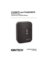
Mounting the KT-PC4204
The KT-PC4204 package should include the following items:
◗One KT-PC4204 circuit board,
◗One ground wire assembly,
◗Five plastic standoffs,
◗One 5 A replacement fuse.
The KT-PC4204 should be located inside a compatible cabinet
(Kantech part no. KT-4051CAB), mounted on a dry, secure
location. Preferably, it should be placed at a convenient distance
from the connected devices.
To mount and connect the power supply:
1. Press the five plastic stands offs through the mounting
holes at back of the cabinet.
2. Secure the cabinet to the wall in the desired location.
Use appropriate wall anchors when securing the cabinet
to dry wall, plaster, concrete, brick or other surfaces.
3. Press the circuit board into the plastic stands offs to
secure the module to the cabinet.
4. Mount the power supply unit.
5. Install 120 / 230VAC / 16VAC, 40VA, class 2 wire-in or
plug-in transformer.
6. Place battery in the cabinet. If the AC supply is removed
form the PC4204, the backup 12volt battery (if fully
charged) will support normal operation for up to 12
hours. An internal battery verification will cut the output
power if the battery voltage level falls below 9.5 V DC.
7. Connect the AWG#18 grounding wire to EGND
NOTE: Since the KT-100 uses high performance communica-
tions, proper grounding must be provided to ensure proper oper-
ation. An AWG#18 single conductor solid copper wire must be
used to ground each KT-PC4204 power supply to a good earth
ground as per the local electrical code (be careful of ground
loops). The ground clamp should be located below any other
ground.
4 Relays Module PC4204
Input: 120 or 230 VAC
Output: 16VAC/40VA
CLASS 2 (WIRE-IN )
To the KT100 controllers
(1.5 amps max.)
NUT
WASHER
CASE
SCREW
EARTH GR OUND
PLUG-IN ALSO AVAILABLE
DO NOT CONNECT TO
RECEPTACLE CONTROLLED
BY A SWITCH
SEALED ACID-LEAD
12 V BATTERY
7A/H MAXIMUM
KANTECH # KT-BD7-12
Jumper

KT-100 Installation Manual
12
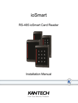
Using the KT-100 with an external alarm
panel
To interface the KT-100 to an external alarm
panel:
1. Connect the KT-100 two inputs (zone 3 and 4) to the
external alarm status relay (PGM1 and PGM2)
2. Connect the KT-100 two outputs (Relay 3 and 4) to the
external alarm system arming status inputs (input 3 and
input 4). These will be used to arm/disarm the external
alarm system as illustrated below.
◗The KT-100 Input (Input 3, in the example) is used to
indicate the arming state of the client party alarm
system. An abnormal status indicates to the KT-100
that the external alarm system is armed.
◗The KT-100 input (Input 4, in the example) is used to
indicate the alarm state of the external alarm. An
abnormal status tells the KT-100 that the external
alarm system is in alarm.
◗The KT-100 output (Relay 3, in the example) is used
as an arm/disarm request of the third party alarm
system. This output is pulsed once to arm or disarm
the alarm system according to the current arming
state.
◗The KT-100 output (Relay 4, in the example) is
connected to a local bell or to warn the alarm panel
of an abnormal condition from the door.
◗Optionally, one KT-100 input zone can be defined
as an arming/disarming request input for the
external alarm panel. In this case, the arming/
disarming request will depend on the door or
external alarm. For example, an arming/disarming
request may be triggered by an access request, a
code entered on the keypad and/or a schedule,
depending on the door status (open or closed) and
the alarm system status (armed or disarmed).
NOTE: For details about interfacing the KT-100 Door Controller
with an external alarm system, please contact our Customer
Assistance at 1 888 KANTECH.
KT-100 Access Controller Alarm System
Relay 3
Relay 4
Input 3
Input 4
Input 3
Input 4
PGM1
PGM2
Door
Contact
T.REX
Card
Reader
Arm/Disarm Request
Controller State
Arming State
Alarm State
Lock
Device BELL
Input 1
Input 2
Lock Out


InOut Systems
Tel: +1(978) 731-6252 • Toll Free: US & Canada: 1 888 222-1560 • Fax: +1(978) 731-7759
Sales: Tel: +1(905) 706-3000 • Toll free: 1 888 888-7838
Web Site: www.inoutsystems.com
E-mails: sales@inoutsystems.com / techlink@tycoint.com
© 2002, InOut Systems, a division of Kantech Systems. All rights reserved.
Specifications may be modified without notice.
™ Trademarks of Kantech Systems.
Printed in Canada • DN5073-0205
/