Page is loading ...

Medium voltage products
UniSec
Installation manual
Safety 3
For your safety! 3
Skilled personnel 3
Crucial information 3
Contact us! 3
1. Introduction 4
1.1 General aspects 4
1.2 Installation manual 4
2. Product information 5
2.1 Unit dimensions 5
2.2 Weights 6
3. Transport and storage 7
3.1 Condition on delivery 7
3.2 Unpacking at installation site 7
3.3 Handling the units as far as the installation site 8
3.4 Temporary storage 10
3.5 Delivery responsibilities 10
4. Assembly of the switchgear on site 11
4.1 General warnings and cautions 11
4.2 Preparations 11
4.3 Dimensional foundation drawings 11
4.4 Foundations 15
4.5 Installation procedure for units 15
4.6 Gas vent ducts 26
4.7 Coupling the units with switch-disconnector
to WBC-WBS units 29
4.8 Coupling the units with switch-disconnector
to WBC unit 24 kV 30
5. Cable connections 31
5.1 Installing the cables 31
5.2 Control cables 37
5.3 Earthing the switchgear 37
5.4 Final installation work 38
A. Tightening torques for steel screws and nuts/bolts 39
B. Tools required for installation 42


3
WARNING
Make sure that the specified electrical
ratings are not exceeded under switchgear
operating conditions. Keep the manuals
accessible to all personnel involved in
installation, operation and maintenance.
The user’s personnel are responsible for all
matters regarding safety in the workplace
and correct use of the switchgear.
Safety
WARNING
Always follow the instructions in the
manual and respect the rules of good
engineering practice (GEP)! Hazardous
voltages can cause serious injury or death!
Disconnect the power and earth live parts
before proceeding with any work on the
apparatus. Follow the safety regulations in
force in the place of installation.
Contact us!
If you have any further questions about this manual, our field
service team will be pleased to help. See the backside of this
manual for contact information.
For your safety!
• Strictly follow this manual.
• Only install switchgear in indoor conditions suitable for
electrical equipment.
• Ensure that installation, operation and maintenance is only
carried out by professional electricians.
• Comply fully with the standards in force (IEC or local), the
connection conditions of the local power utility and the
applicable safety at work regulations.
• Observe the relevant information in the manual for all actions
involving the switchgear.
• For use of the circuit-breaker, refer to the instruction booklet.
Skilled personnel
All the installation, putting into service, running and mainte-
nance operations must be carried out by skilled personnel with
in-depth knowledge of the apparatus.
When carrying out any maintenance work, the regulations in
the country of installation must be strictly complied with.
Maintenance work must only be performed in a professional
way by trained personnel familiar with the characteristics of
the switchgear, in accordance with all the relevant IEC safety
regulations and those of other technical authorities, also
respecting other overriding instructions. It is recommended
that ABB service personnel be called in to perform the servicing
and repair work.
Crucial information
Pay special attention to the information shown in the manual by
the following symbol:
After this symbol there are four different indications which
explain the possible type of injuries or damage which may be
caused when the instructions, including recommended safety
precautions, are not followed.
• DANGER - identifies the most serious and immediate
hazards which can result in serious personal injury or
death
• WARNING - identifies hazards or unsafe practices which
can result in serious personal injury or death
• CAUTION - identifies hazards or unsafe practices which
can result in minor personal injury or product or property
damage
• NOTE - identifies important procedures or requirements
that, if not followed, can result in product or property
damages

4
1. Introduction
1.1 General aspects
UniSec is an air-insulated switchgear for indoor use, designed
for medium voltage secondary distribution. UniSec switchgear
is the result of continuous innovation, following the desire to
meet ever-changing market needs.
This new series of switchgear offers a wide range of long-term
technical solutions.
Safety, reliability, user-friendliness and simplicity of installation,
as well environmental sustainability were the driving forces in
developing this switchgear.
UniSec is structured by placing standardized units side by side
in a coordinated way. Construction and testing are carried out
in the factory.
1.2 Installation manual
This manual provides information on installation of UniSec units.
It contains details about product dimensions and weights, as
well as instructions for unpacking and delivery to the installation
site. Step-by-step instructions show the procedure for installing
the switchgear.

5
375 500
750
600
750
1188
1037
117.5
33.5
1700
335
2035
1215
110
1700
1870
1918
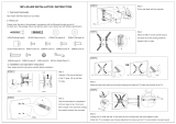
2.1 Unit dimensions
Drawings
The following drawings illustrate the main dimensions and
space requirements of the different units.
2. Product information
Front views of the various units
Figure 1. SDC 375 Figure 2. SFC 500 Figure 5. SBC 750Figure 3. WBC 600 Figure 4. WBC 750
Side view of the different units
Figure 6. Without circuit-breaker
(with a gas vent duct)
Figura 7. Without circuit-breaker
(with gas vent filters)

6
1180
171
1868
600194.5
1037
1139.5
102.5
1167
1200
33
2000
1300
1267 33
2000
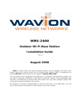
2.2 Weights
The following table shows the maximum weights of the different
units.
Unit (mm) Weight (kg)
375 250
500 400
600 800
750 600/750
(*)
(*)
WBC @ 24 kV
Table 1. Maximum weights of units
Figure 8. With large auxiliary circuits compartment
and VD4 circuit-breaker (without gas vent ducts)
Figure 9. With Vmax withdrawable circuit-breaker
(without gas vent ducts)
Figure 10. WBC 24 kV

7
3. Transport and storage
Packing materials
Table 2. lists all the packing materials used in the switchgear:
Raw material Possible recycling method
Plywood Recycling or disposal
Unplaned wood products Recycling or disposal
Antistatic polythene film Recycling or disposal
Polythene shrink wrap Recycling or disposal
VCI (vapour corrosion inhibitor) film Recycling or disposal
Tape Recycling or disposal
Folded cardboard and polystyrene
reinforcements
Recycling or disposal
Corner protections Recycling or disposal
Table 2. Packing materials
Figure 11. Fixing plates outside the 375-500 mm unit
Figure 12. Fixing plates outside the 750 mm unit
Figure 13. Bolt inside the unit (left side)
3.1 Condition on delivery
Delivery packing
UniSec is delivered either as a single unit or in multiple switch-
gear units with a length of no more than 2.0 m, and with the
doors closed. The size of the pack(s) depends on the number
and type of units and has to be defined separately in each
case.
The factory-assembled units have been inspected by the man-
ufacturer in the factory for completeness in terms of the order
and, at the same time, subjected to routine testing according
to IEC publication 62271-200 in order to verify correct con-
struction and functions.
The branch busbars are factory-assembled for each unit.
However, the main busbar connections between different
units must be carried out on site. The main busbars and their
accessories are packed separately for delivery.
3.2 Unpacking at installation site
Storage and inspection
The UniSec switchgear must only be installed indoors. It is
therefore important to store the switchgear units in their trans-
port packing for as long as possible. Do not store switchgear
units outside.
The packs should only be opened to inspect for any damage
caused during transport. After inspection, the packing should
be restored to its original condition.
NOTE
Any transport damage must be reported to the
carrier/forwarder immediately. If installation
of the switchgear is to be made immediately
after delivery, the transport packing must
be removed, except for the plastic vapour
corrosion inhibitor film covering the units,
which must only be removed at the final
switchgear installation site.
Unpacking
The UniSec units are fixed to the pallet using separate fixing
plates (2 plates on the back of the unit) and bolts (2 bolts on
the front of the unit) inside the unit.
a) Remove the plastic film from the units.
b) Take off and dispose of the fixing plates and bolts as these
will not be needed.
c) The table shows a list of the packing materials used for
the switchgear units and their possible recycling methods.
Packing materials may vary from case to case. The list gives
an indication of the possible packing materials.

8
Figure 14. Bolt inside the unit (right side)
3.3 Handling the units as far as the instal-
lation site
3.3.1 General warnings and cautions
3.3.2 Instructions
Transport units
The transport units consist of individual units or small groups
of units. The lifting hooks are suitable for all UniSec units
(375 mm, 500 mm, 600 mm and 750 mm).
Handling instructions
The units must be handled in the upright position using a
manual forklift or a forklift truck or, exceptionally, using special
rolling tubes (at least four).
DANGER
Only carry out loading operations when it
has been ensured that all precautionary
measures to protect personnel and materials
have been taken.
CAUTION
The switchgear units should usually be
handled in an upright position. Take the
high centre of gravity into account. Tilting or
overturning must be avoided. If necessary,
single units can be carried horizontally, for
example, because of a low doorway. In such
cases, the unit must be supported over a
wide area.
CAUTION
The packages should be placed on a level
surface.
Lifting instructions
Use the following tools for lifting:
• Crane
• Fork-lift truck and/or
• Manual trolley jack.
NOTE
It is also possible to move units on a flat floor
to the installation site by using rolling tubes.
The rolling tube dimensions should be about
1 m in length and 20-25 mm in diameter.
3.3.3 Lifting procedure
Parts
Figure 15. Lifting hook
Figure 16. Roof frame on the top of the unit
Operations to be carried out before lifting
a) Install the lifting hooks on the roof frame.
Figure 17. Roof frame + lifting hooks
Figure 18. Lifting hooks installed on roof frame
b) Repeat the operation for all four corners of the roof frame.
If a crane is available, lifting can be done by using the lifting
hooks which are delivered separately. The lifting procedure,
including how to install the lifting hooks, is illustrated on the
right.

9
Switchgear ready for lifting: lifting hooks installed
Figure 19. 375 mm, 500 mm and 600 mm UniSec units
Figure 20. 750 mm UniSec unit
Lifting dimensions and angle
When lifting using a crane, proceed as follows:
a) Fit lifting ropes of an appropriate load capacity with spring
catches.
b) Keep an angle of at least 60° between the horizontal plane
and the ropes leading to the crane hook.
Figure 21. Dimensions and angles
Lifting by crane
CAUTION
Four lifting ropes of sufficient length must
be used when lifting several units or a
whole switchgear (4 units at the most, or a
maximum length of 2 m).
Figure 22. Lifting
Operations after lifting
a) Dismantle the lifting hooks.
b) The same hooks are used again for the next unit.

10
3.4 Temporary storage
3.4.1 General warnings and cautions
CAUTION
The packing must be kept indoors immedi-
ately after arrival. The conditions must meet
the environmental requirements of the IEC
60721-3-1 Standard, classification 1K3.
CAUTION
The vapour corrosion inhibitors placed in the
units for protection against humidity during
temporary storage and transport must not be
removed until installation is completed.
CAUTION
The duration of the protective effect of the
packing is limited to a few months when
stored indoors in a dry place. ABB should
be consulted in the case of longer storage
periods or if the storage conditions differ
from those indicated.
3.4.2 Optimum storage conditions
Definition: Optimum temporary storage, without negative
consequences, depends on compliance with the minimum
requirements for the units and packing materials.
Minimum air temperature °C - 5
Maximum air temperature °C + 40
Minimum relative humidity % 5
Maximum relative humidity % 95
Rate of temperature change °C/min 0.5
Table 3. Climatic conditions according to IEC 60721-3-1, classifi cation 1K3.
Type of packing
Special instructions depending on the type of packing are
given below:
1. Units with basic packing or without packing
1) Use a dry, well-ventilated place with climatic conditions in
accordance with Table 3.
2) Store the units upright.
3) Do not stack units.
4) Units with basic packing:
• Open the packing, at least partially.
5) Units without packing:
• Cover with non-adherent protective sheeting.
• Ensure there is sufficient air circulation.
• Regularly check for any condensation until installation is
started.
2. Units with seaworthy or similar packing with internal
protective sheeting
1) Store the transport units:
• protected from the weather,
• in a dry place,
• safe from any damage.
2) Check the packing for any damage.
3.5 Delivery responsibilities
Responsibilities
The responsibilities of the consignee when the switchgear
arrives on site include, but are not limited to, the following:
• Checking the consignment for completeness and lack of
any damage (e.g. for signs of humidity and its detrimental
effects). In case of doubt, the packing must be opened and
then properly resealed.
NOTE
Always take photographs to document any
major damage.
• The packing list includes any separate additional material
(not installed). This material can often be found in the first
unit of the switchgear.
If any quantities are short, or defects or transport damage are
noted, these must be:
• Documented on the respective shipping document.
• Immediately notified to the relevant carrier or forwarding
agent in accordance with the relative liability regulations.

11
(*)
(*)
(*)
4. Assembly of the switchgear on site
WARNING
In order to obtain an optimal installation
sequence and ensure high-quality standards,
on-site installation of the switchgear must
only be carried out by specially trained and
skilled personnel, or at least by personnel
supervised and monitored by competent and
responsible people.
4.1 General warnings and cautions
WARNING
Once the documents have been prepared for
final mounting, the binding data supplied by
ABB must always be taken into account!
NOTE
Where switchgear units have roof-mounted
gas vent ducts or large auxiliary circuit
compartments, it must be ensured that the
ceiling height is sufficient for these.
4.2 Preparations
Before starting
To commence installation on site, the switchgear room must
be absolutely suitable, i.e. provided with lighting and electricity,
fitted with a padlock, ventilation facilities and must also be dry.
All the necessary preparations, such as wall openings, ducts,
etc. for laying the power and control cables as far as the
switchgear, must already have been completed.
Before proceeding with installation:
a) Clean the installation site
b) Visibly trace the perimeter of all the units making up the
switchgear on the slab, taking the minimum clearances of
wall and any obstacles into account.
NOTE
When gas vents or absorbers are foreseen,
there must be a minimum space of 185 mm
between the back of the switchgear and the
installation room wall.
4.3 Dimensional foundation drawings
4.3.1 Room layout
Figure 23. Minimum distances to
the installation room walls with gas
absorbers.
Class AFLR
Figure 24. Minimum distances to the
installation room walls with gas vent
ducts.
Class AFLR
Switchgear supplied with 1 m long
external duct.
(*)
>1200 mm for panels with removable circuit-breaker

12
200
375
85 90
43.5
43.5
158.5
248
Ø12.5
600
1037
189
78.5
958.5
200
500
147.5 152.5
43.5
43.5
158.5
248
Ø12.5
600
1037
189
78.5
958.5
100
150
25
25
158.5
248
Ø12.5
600
1037
4.3.2 Cable passage hole dimensions and fixing points
The following figures show the locations and sizes of the cable
passage holes under the different units. These holes must be
made before installation of the switchgear. The figures also
Figure 27. 375 mm wide units Figure 28. 500 mm wide units
show the switchgear fixing points. There is one fixing point in
each corner of the unit (4 per unit). Units without cable entry
have dimensions and fixing points according to the width of the
unit 10 mm anchoring bolts can be used for fixing.
Figure 25. Minimum distances to
installation room wall with gas
absorbers.
Class ALFR.
Figure 26. Minimum distances to the
installation room walls with gas vent
ducts.
Class AFLR.
Switchgear supplied with 1 m long
external duct.
Figure 29. 190 mm wide for
RLC/RRC unit (for SBR only)

13
200
355 195
43.
5
43.5
158.5
248
Ø12.5
600
1037
189
78.5
958.5
200
750
275 275
43.5
43.5
158.5
248
Ø12.5
600
1037
189
78.5
958.5
400
600
100 100
43.5
43.5
10
301.5
Ø12.5
753
230
1200
800
125
81
550
750
100
100
43.5
43.5
10
301.5
773
230
1300
800
125
81
25
Ø12.5
Figure 30. 750 mm wide units Figure 31. 750 mm wide for SBR unit
Figure 32. 600 mm width for units with
withdrawable circuit-breaker up to 17.5 kV
Figure 33.750 mm width for unit with
withdrawable circuit-breaker at 24 kV

14
4.3.3 Medium voltage cable locations and lengths
The medium voltage cable lengths (distance of the cable con-
nection point from the floor) depend on the units and acces-
sories used. The following figures and table show the cable
lengths and locations for the different units.
Table 4. Medium voltage cable lengths and locations
Figure 34. Medium voltage cable lengths
RLC unit
Details
190 mm width 375 mm width 500 mm width 600 mm width 750 mm width
A (mm) B (mm) A (mm) B (mm) A (mm) B (mm) A (mm) B (mm) A (mm) B (mm)
SDC Basic
––915210915275––––
SDC With CT
––––525275––525275
SDM Basic
–––––––– 525
(1)
275
(1)
SFC 292 mm fuse
––600200600230––––
SFC 442 mm fuse
––450200450230––––
SBC Basic
––––––––500310
WBC Basic or with CT
––––––600 150
(2)
600 165
DRC Basic
––500165670255––––
DRC With CT
––––530275––––
SBR Basic
––––––––400390
RLC/RRC Basic
1495 310 ––––––––
(1)
With optional cable terminal
(2)
Distance between panel side wall and fi rst cable connection

15
4.4 Foundations
4.4.1 Foundation types
General aspects
The switchgear must be erected on a foundation that fulfils the
requirement of a 2 mm maximum horizontal height deviation
in relation to the length and diagonal of the switchgear. As it
is difficult to make a concrete foundation that fulfils the above
levelness requirement, adjustments are made using a metal
frame or by installing steel plates under the corners of the
units. The load capacity of the floor and foundation must also
be sufficient.
Figure 35. Switchgear erected on a metal frame
Figure 36. Switchgear erected on a floating floor
If the switchgear only consists of a few units and no heavy units
are included, it can be installed on the concrete floor.
Figure 37. Switchgear installed on a concrete floor
4.5 Installation procedure for units
4.5.1 Assembly of the first two switchgear units
WARNING
Before positioning the different switchgear
units, check the floor levelling, with par-
ticular attention to the longitudinal flatness
(maximum levelness 2/1000).
NOTE
If horizontal gas vent ducts are provided,
mount the joint brackets unit by unit right
from the start (see 4.6.2).
4.5.2 Removing roof plates
Plate dismantling is carried out as follows:
a) Unscrew the screws present at both ends of the roof.
b) Remove the plate.

16
Figure 38. 375 mm wide units
Figure 39. 500 mm wide units
4.5.3 Connecting the units
Note: for SBR units, do not remove the roof frame.
Installation foresees the following operations:
a) Align two units side by side. Before pushing the two units com-
pletely together, make sure that the lower joining plate of the
right-hand unit is in the upper position as shown in Figure 41.
Figure 40. Two units side by side
Figure 41. Outline of lower joining plate in upper position
b) Hammer the lower joining plate down so that the units are
firmly fixed to each other at the back.
Figure 42. Installation of lower joining plate
c) Screw up the lower joining plate (with Torx M6x12 screws).

17
Figure 43. Screw for the lower joining plate
d) Slide the joining plate to the fixing point of the units (on the
inner rear wall).
Figure 44. Installation of top joining plate
e) Screw the joining plate and the unit plates together (with 6
Torx M6x12 screws) so that they are fully tightened. Insert a
bolt (M8x20 round-headed with square neck) with a nut (M8
hexagonal nut with flange) (figure 45) to tighten the units and
the joining plate.
Figure 45. Screws for the top joining plate
Figure 46. Plates installed
f) Insert 5 bolts (M10x20 hexagonal with flange) and 5 nuts
(M10x20 hexagonal with flange) into the LV and instrument
compartment (front, upper part of the units), but do not
tighten them yet.

18
Figure 49. Screw positions for WBC – WBS units
4.5.4 Assembling the remaining switchgear units
After connecting two units, bring the third unit to the place of
installation. Then repeat the following operations:
a) Removing the roof plates
b) Connecting the units
c) Repeat the same operations for the remaining units.
Figure 47. Places for screws
g) Insert 8 bolts (M10x20 hexagonal with flange) and 8 nuts
(M10x20 hexagonal with flange) into the cable compartment
(front, lower part of the units), but do not tighten them yet.
Figure 48. Screw positions
h) Use a screwdriver to trim the unit alignment. Tighten all the
bolts from the front.
NOTE
Do not remove the roof frame for SBR
functional units.
i) For WBC and WBS units, insert 6 hexagonal bolts with the
relative nuts.

19
The busbar connections are made through the top openings
a) Clean and scrape the busbar connections.
b) Clean the insulation of the busbar sections with a soft, dry
cloth and check for any insulation damage.
c) Install the busbars unit by unit. Insert the screws, busbars
and other required components in the correct positions
and tighten them to the correct torques according to the
instructions given below.
Instructions for different types of main busbar connections
The main busbars overlap each other at their contact points.
This means that every other busbar is mounted on top of the
other, as shown in Figure 51. Busbar spacers are used in
the end units to keep the busbars in a completely horizontal
position.
Figure 51. Main busbar connections
4.5.6 Connecting the main busbars
General warnings and precautions
DANGER
A warning sign is placed on the top plate to
indicate the presence of high voltage under
the roof.
CAUTION
It is recommended to mount the busbars
starting from the top of the units.
NOTE
Tighten to the correct torque. The torques
are indicated in the “Tightening torques for
steel screws and nuts/bolts” table.
NOTE
It is important for the screws to be of the
correct length.
Busbar spacer Busbar Busbar spacer
1
Odd
numbered
unit
2
Even
numbered
unit
3
Odd
numbered
unit
4
Even
numbered
unit
5
Odd
numbered
unit
4.5.5 Fixing the switchgear to the floor
(See Figures 35, 36 and 37).
Fixing to the metal frame
a) The switchgear must be fixed to the metal frame by welding
through the holes in the bottom of the unit (2 welding seams/
unit) or with two bolts/unit straight into the concrete floor.
b) Fix as shown in Figure 50.
Figure 50. Fixing the switchgear to the floor
Fixing to a concrete floor with anchoring bolts
a) Level the floor both longitudinally and transversely.
b)
Drill the fl oor at the fi xing points, referring to the slab drilling dia-
grams. Use a hammer drill with a suitable bit to make the holes.
c) After installing the unit, insert the expansion anchoring bolts
into the holes.
d) Fix as shown in Figure 50.
Fixing to a floating floor
a) Drill the floor at the fixing points, referring to the slab drilling
diagrams. Use a drill with a suitable bit for the type of fixing
to be carried out to make the holes (smooth or threaded
through hole).
b) Fix as shown in Figure 50.

20
Figure 52. Example of main busbar connections
for 3 SDC 375 units (with 12-17.5 kV)
NOTE
Insulating terminal covers are installed in the
end units. For 24 kV, a rubber terminal cap is
installed in all the units.
NOTE
Make sure the busbar spacers are positioned
as shown in the figures below.
The following figures show the busbar connections for units
with switch-disconnector. The components required are indi-
cated in Table 5. The main busbar connections of each unit
type with different rated currents and voltages are shown. Each
figure gives a reference to the corresponding numbers of the
components in Table 5.
All unit types
Part Name
1. Round-headed socket screw M10x40
2. Round-headed socket screw M10x45
3. Round-headed socket screw M10x50
4. Round-headed socket screw M10x60
5. Cheese-head socket screw M10x65
6. Cheese-head socket screw M10x70
7. Rubber cap for local terminal
8. Ring field control
9. Insulating terminal cover
10. Insert
11. Busbar
12. Conical spring washers D10
13. Hexagonal nut M10
14. Busbar spacer
15. Shim washer d20x2
16. Round-headed socket screw M10x30
17. Hexagonal-headed screw M12x40
18. Hexagonal-headed screw M12x60
19. Nut M12
20. Conical spring washer D12
21. Round-headed socket screw M12x50
22. Busbar spacer D12
23. Round-headed socket screw M12x30
Table 5. List of components used
/