Page is loading ...


i
Quick Links
Scanner
Intelligent Diagnostics
Compact Scan Module
OBD Direct
Guided Component Tests
Scope Multimeter
Information
Vehicle History
Data Manager
Help
System Settings
General Information
Getting Started
Maintenance
Quick Reference Information
Using Page Controls
Table of Contents (TOC)
Click a Topic
Contents

ii
Contents Table of Contents
Safety Information .......................................................................................1
READ ALL INSTRUCTIONS.......................................................................... 1
Safety Signal Words ...................................................................................... 1
Safety Message Conventions ........................................................................ 2
Safety Message Example .............................................................................. 2
Important Safety Instructions ......................................................................... 2
Using This Manual ....................................................................................... 3
Page Navigation Controls ............................................................................. 3
Conventions................................................................................................... 3
Hyperlinks................................................................................................ 3
Procedures .............................................................................................. 3
Bold Text .................................................................................................3
Symbols................................................................................................... 4
Terminology............................................................................................. 4
Notes and Important Messages .............................................................. 4
Quick Reference .......................................................................................... 5
Introduction .................................................................................................... 5
Main Topic Links............................................................................................ 5
Quick Links .................................................................................................... 5
Support Contact Information .......................................................................... 5
Phone / E-mail - Technical Assistance.................................................... 5
Website: ..................................................................................................5
Information Service ........................................................................................ 5
Product Training Videos.................................................................................6
Common Abbreviations Used ........................................................................ 6
Section 1: General Information...................................................................7
Introduction .................................................................................................... 7
Main Topic Links............................................................................................ 7
Internal Battery Pack ............................................................................... 9
Turning On/Off, and Emergency Shutdown ................................................... 9
Turning On ..............................................................................................9
Turning Off .............................................................................................9
Emergency Shutdown ........................................................................... 10
Configure Shortcut (S) Button ...............................................................11
Advanced (menu selection) .................................................................. 11
Camera (Taking Pictures)............................................................................ 11
Using the Camera ................................................................................. 11
Viewing Pictures.................................................................................... 12
Windows (Applicable Features / Operations) .............................................. 12
Wi-Fi Setup ........................................................................................... 12
Windows Taskbar.................................................................................. 13
Windows Taskbar Notification Area ..................................................... 13
Touch Screen and Stylus...................................................................... 13
Virtual Keyboard (Entering Text).......................................................... 14
Sleep Mode (Auto Off Display).............................................................. 15
E-Mail Client Setup ............................................................................... 16
Calibrating the Touch Screen...................................
............................. 18
Printing / P
rinter Setup
.......................................................................... 19
Default Printer Setting........................................................................... 21
Checking/Installing Adobe® Reader ..................................................... 21
Operating System Restore .......................................................................... 22
Accessories (Optional Equipment) ............................................................. 22
Diagnostic Tool Technical Specifications .................................................... 23
Section 2: Getting Started - Diagnostic Suite Program ......................... 24
Introduction.................................................................................................. 24
Main Topic Links.......................................................................................... 24
The ShopStream Diagnostic Suite Program................................................ 24
Home Screen Layout................................................................................... 24
Function Icons ............................................................................................. 25
Menu Icon.................................................................................................... 26
Safety Information................................................................................. 26
Help....................................................................................................... 26
Changing the Units of Measurement ........................................................... 27
Section 3: Compact Scan Module (CSM) ................................................ 28
Introduction.................................................................................................. 28
Main Topic Links.......................................................................................... 28
Power Source .............................................................................................. 28
LED Indicators ............................................................................................. 29
Audible Alerts .............................................................................................. 29
LED Flashlight (built-in) ............................................................................... 29
Basic Operation ........................................................................................... 30
Table of Contents

iii
Contents Table of Contents
Connecting the CSM .............................................................................30
Pairing and Hardware Status Icons....................................................... 31
Firmware Updates........................................................................................ 33
Troubleshooting ........................................................................................... 34
Error Messages .....................................................................................35
Out of Range Alarm...............................................................................35
Loss of Connection - Recovery Procedures.......................................... 35
Technical Specifications ..............................................................................36
Section 4: Scanner ....................................................................................37
Introduction ..................................................................................................37
Main Topic Links.......................................................................................... 37
Scanner Overview .................................................................................37
Basic Scanner Operation (Quick Start) ................................................. 38
Identifying the Vehicle .......................................................................... 38
Selecting a Vehicle System................................................................... 39
Selecting a Vehicle System Test/Function ............................................40
Exiting Scanner .....................................................................................41
Menu Options (lower toolbar icon) ...............................................................41
File......................................................................................................... 42
Tools...................................................................................................... 42
Help .......................................................................................................42
Codes Menu (Viewing Codes) .....................................................................43
Display Codes (Code List)..................................................................... 43
Clear Codes ..........................................................................................44
Freeze Frame/Failure Record Data.......................................................44
Code Scan (with Vehicle System Report).................................................... 45
Saving the Vehicle System Report .......................................................47
Edit Vehicle System Report Shop Information .....................................47
Hide / Show Vehicle System Report Timestamp .................................. 47
Printing the Vehicle System Report....................................................... 47
Clear All Codes Read by Code Scan .................................................... 48
Data (Viewing PIDs)..................................................................................... 48
Data Screen Overview ..........................................................................49
Using Triggers .......................................................................................58
Functional Tests ..........................................................................................62
Functional Resets and Procedures .......................................................63
Generic Functions........................................................................................63
Troubleshooter.............................................................................................64
Demonstration Modes.................................................................................64
Scanner Demonstration (Introduction to Intelligent Diagnostics)................. 64
Section 5: Intelligent Diagnostics ........................................................... 68
Introduction.................................................................................................. 68
Main Topic Links.......................................................................................... 68
Accessing Intelligent Diagnostics ................................................................ 68
Main Menu and Basic Navigation ............................................................... 69
Code Results Dropdown Menu........................................
....
........................ 70
Top Repairs Graph ...................................................................................... 71
Technical Bulletins (OEM Information) ........................................................ 71
Smart Data .................................................................................................. 72
About Prearmed Smart Data PIDs ........................................................ 73
Functional Tests and Reset
Procedures ........................................................................................ 73
Guided Component Tests (GCTs)............................................................... 74
Real Fixes.................................................................................................... 76
Tips.............................................................................................................. 76
Repair Information ....................................................................................... 76
Section 6: OBD Direct .............................................................................. 77
Introduction.................................................................................................. 77
Main Topic Links.......................................................................................... 77
Main Menu................................................................................................... 77
OBD Diagnose............................................................................................. 77
Start Communication............................................................................. 77
Connector Information........................................................................... 80
Manual Protocol Selection .................................................................... 80
OBD Health Check ...................................................................................... 80
Global OBD II Code Check ................................................................... 80
Global OBD II Clear Codes ................................................................... 81
Section 7: Guided Component Tests....................................................... 82
Introduction.................................................................................................. 82
Main Topic Links.......................................................................................... 82
Safety Information ....................................................................................... 82
General Information..................................................................................... 83
Configuring the Favorites List ............................................................... 83
Menu Icon ............................................................................................. 84
Training and Classes ............................................................................ 84
Vehicle Identification.................................................................................... 86
Tests............................................................................................................ 87
View Meter ............................................................................................ 88
Performing a Test.................................................................................. 88

iv
Contents Table of Contents
Section 8: Scope and Multimeter Operations ........................................ 89
Introduction ..................................................................................................89
Main Topics Links ........................................................................................89
Measurement Out of Range Indicator ..................................................90
Getting Started.............................................................................................90
Technical Specifications
(Scope Module) ...........................................................................................91
Tests and Capabilities (Quick Reference).............................................92
Digital Multimeter (DMM).......................................................................93
Graphing Multimeter (GMM).................................................................. 94
Lab Scope .............................................................................................95
Ignition Scope (Secondary Ignition Tests).............................................96
Presets .................................................................................................. 97
General Instructions.....................................................................................97
Test Lead / Probe Connection...............................................................97
Using the Scope Module Remotely ....................................................... 98
Pairing and Hardware Status Icons....................................................... 99
Test Lead / Probe Calibration................................................................ 99
Main Screen and Toolbars......................................................................... 100
Scope/Meter (Upper) Toolbar..............................................................101
Main Body of the Screen .....................................................................101
Setup Menu (Preferences).........................................................................101
Trace Controls Menu........................................................................... 101
Trigger Setup Menu............................................................................. 102
View Controls ......................................................................................102
Setup Controls.....................................................................................106
Control Panel and Settings ........................................................................ 108
Display Modes..................................................................................... 109
Control Panel (Trace Controls Quick Reference)................................110
Profile Icon .......................................................................................... 110
Channel Icon .......................................................................................111
Probe Icon ...........................................................................................111
Peak Detect Icon .................................................................................111
Filter Icon............................................................................................. 112
Invert Icon............................................................................................113
Coupling AC Icon ................................................................................ 113
Slope (Trigger) Icon.............................................................................113
Scale (Vertical / Y-axis) ....................................................................... 113
Sweep Scale (X-axis) .......................................................................... 114
Min, Live and Max Display Panel ........................................................115
Zero Baseline Adjustment ................................................................... 115
Threshold Auto/Manual (GMM Only) .................................................. 115
Triggers ..................................................................................................... 118
Trigger Setup Menu ............................................................................ 118
Trigger Operation................................................................................ 119
Cursors ............................................................................................... 120
Saving and Reviewing Scope / Multimeter Data Files............................... 122
About the Data Buffer ..........................................
............................... 122
Saving D
at
a Files / Configurations...................................................... 122
Record/Playback Control Toolbar ....................................................... 123
Stopping and Reviewing Data Files .................................................... 123
Snapshot Icon ..................................................................................... 124
Using the Zoom Function .................................................................... 125
Test Leads and Accessories ..................................................................... 126
Channel 1 Lead................................................................................... 127
Channel 2 Lead................................................................................... 127
Channel 3 Lead .................................................................................. 127
Channel 4 Lead................................................................................... 127
Alligator Clips and Probes................................................................... 127
Secondary Ignition Coil Adapter Lead and Clip-on Adapter (optional) 128
Inductive RPM Pickup Adapter (optional) ........................................... 128
Low Amp Current Probe (optional)...................................................... 128
Temperature Probe Adapter (optional) ............................................... 128
Pressure Transducers and Adapters (optional) .................................. 129
Waveform Demonstration Tools (optional).......................................... 129
General Reference ................................................................................... 130
Basic Setup Tips (unknown signal type) ............................................ 130
Using Known Good Waveforms .......................................................... 131
Troubleshooting Signals ..................................................................... 131
Units of Measurement / Conversions .................................................. 132
Glossary of Common Terms .............................................................. 134
Section 9: Information............................................................................. 136
Topic Links ................................................................................................ 136
Introduction ............................................................................................... 136
Connection.......................................................................................... 137
Status (Alert) Messages...................................................................... 137
Getting Started .......................................................................................... 137
Vehicle Identification ........................................................................... 137
The Snap-on Information Application ........................................................ 138
Main Screen........................................................................................ 138

v
Contents Table of Contents
Overview.................................................................................................... 142
Fault Code Search ............................................................................. 142
Maintenance .............................................................................................142
Repair Data................................................................................................144
Electronics ................................................................................................ 147
Electronic Systems..............................................................................148
Fuses and Relays................................................................................ 152
Locations .............................................................................................152
Electronic Procedures .........................................................................153
Warning Lights and Indicators............................................................. 153
SmartPACK™ ...........................................................................................153
SmartCASE .........................................................................................154
Recall Data.......................................................................................... 155
Technical Service Bulletins .................................................................155
Section 10: Vehicle History..................................................................... 156
Introduction ................................................................................................156
Main Topic Links........................................................................................ 156
Toolbar Icon Functions .............................................................................. 157
Activate............................................................................................... 157
View.....................................................................................................157
Delete .................................................................................................. 158
Manage .............................................................................................. 158
Search and Show All ...........................................................................158
Settings .............................................................................................. 159
Section 11: Data Manager .......................................................................160
Introduction ................................................................................................160
Main Topic Links........................................................................................ 160
Data Manager Screen Layout.................................................................... 160
General Information ................................................................................... 161
File Location .......................................................................................161
Moving / Copying Files ....................................................................... 161
Printing Files ....................................................................................... 161
Viewing Saved Files ...........................................................................161
About Saved Folder/File Structure ...................................................... 162
Toolbar Icon Functions ............................................................................. 162
Email ...................................................................................................163
Vehicle System Report Viewer .................................................................164
Image Viewer ............................................................................................164
Scanner DataViewer ..................................................................................165
Menu Bar ............................................................................................ 165
Display Toolbar ................................................................................... 167
Navigation Tools ................................................................................. 168
Customizing the Display...................................................................... 169
Customizing the Parameter List ......................................................... 169
Section 12: Help....................................................................................... 171
Introduction................................................................................................ 171
Toolbar Icons............................................................................................. 171
Page Navigation Controls .........................................
...
............................. 172
Section 13: System Settings .................................................................. 173
Introduction................................................................................................ 173
Topic Links ................................................................................................ 173
Shop Information ....................................................................................... 174
Data Backup .............................................................................................. 174
Backup Settings (message) ................................................................ 174
Backup ................................................................................................ 174
Restore ............................................................................................... 175
Code Scan (Timestamp)............................................................................ 175
Section 14: ShopStream Update Tool (SST) ......................................... 176
Introduction................................................................................................ 176
Terminology............................................................................................... 176
Topic Links ................................................................................................ 176
Basic Operation ......................................................................................... 177
End User License Agreement.................................................................... 177
Manual Download...................................................................................... 178
Installing Software Updates....................................................................... 179
Installing Software Upgrades..................................................................... 180
Section 15: Maintenance......................................................................... 182
Introduction................................................................................................ 182
Main Topic Links........................................................................................ 182
Cleaning .................................................................................................... 182
Cleaning the Diagnostic Tool .............................................................. 182
Cleaning the Touch Screen................................................................. 182
Cleaning the Compact Scan Module (CSM) ....................................... 182
Battery Pack .............................................................................................. 183
Safety ................................................................................................. 183
Battery Pack Replacement.................................................................. 184
Battery Pack Disposal ......................................................................... 184

vi
Contents Table of Contents
Screen Protector Installation......................................................................185
Stylus Tip Replacement (Touch Screen) ...................................................186
Legal Information..................................................................................... 187
Trademarks................................................................................................187
Copyright Information.................................................................................187
Software License Information .................................................................... 187
Patent Information ..................................................................................... 187
Disclaimer of Warranties and Limitation of Liabilities.................................187
***IMPORTANT INFORMATION*** ...........................................................187

1
Safety Information
READ ALL INSTRUCTIONS
For your own safety, the safety of others, and to prevent damage to the product and
vehicles upon which it is used, it is important that all instructions and safety
messages in this manual and the accompanying Important Safety Instructions
manual be read and understood by all persons operating, or coming into contact
with the product, before operating. We suggest you store a copy of each manual
near the product in sight of the operator.
For your safety, read all instructions. Use your diagnostic tools only as described in
the tool user’s manual. Use only manufacturer recommended parts and
accessories with your diagnostic tools.
This product is intended for use by properly trained and skilled professional
automotive technicians. The safety messages presented throughout this manual
and the accompanying Important Safety Instructions manual are reminders to the
operator to exercise extreme care when using this product.
There are many variations in procedures, techniques, tools, and parts for servicing
vehicles, as well as in the skill of the individual doing the work. Because of the vast
number of test applications and variations in the products that can be tested with
this instrument, we cannot possibly anticipate or provide advice or safety messages
to cover every situation. It is the responsibility of the automotive technician to be
knowledgeable of the system being tested. It is essential to use proper service
methods and test procedures. It is important to perform tests in an appropriate and
acceptable manner that does not endanger your safety, the safety of others in the
work area, the equipment being used, or the vehicle being tested.
It is assumed that the operator has a thorough understanding of vehicle systems
before using this product. Understanding of these system principles and operating
theories is necessary for competent, safe and accurate use of this instrument.
Before using the equipment, always refer to and follow the safety messages and
applicable test procedures provided by the manufacturer of the vehicle or
equipment being tested. Use the product only as described in it’s user manual. Use
only manufacturer recommended parts and accessories with your product.
Read, understand and follow all safety messages and instructions in this manual,
the accompanying Important Safety Instructions manual, and on the test
equipment.
Environmental Conditions:
• This product is intended for indoor use only
• This product is rated for Pollution Degree 2 (normal conditions)
Safety Signal Words
All safety messages contain a safety signal word that indicates the level of the
hazard. An icon, when present, gives a graphical description of the hazard. Safety
Signal words are:
'$1*(5
Indicates an imminently hazardous situation which, if not avoided, will result in
death or serious injury to the operator or to bystanders.
:$51 ,1*
Indicates a potentially hazardous situation which, if not avoided, could result in
death or serious injury to the operator or to bystanders.
&$87,21
Indicates a potentially hazardous situation which, if not avoided, may result in
moderate or minor injury to the operator or to bystanders.

Safety Information Safety Message Conventions
2
Safety Message Conventions
Safety messages are provided to help prevent personal injury and equipment
damage. Safety messages communicate the hazard, hazard avoidance and
possible consequences using three different type styles:
• Normal type states the hazard.
• Bold type states how to avoid the hazard.
• Italic type states the possible consequences of not avoiding the hazard.
An icon, when present, gives a graphical description of the potential hazard.
Safety Message Example
Risk of electric shock.
• Prior to recycling the battery pack, protect exposed terminals with heavy
insulating tape to prevent shorting.
• Disconnect all test leads and turn diagnostic tools off before removing the
battery pack.
• Do not attempt to disassemble the battery or remove any component
projecting from or protecting the battery terminals.
• Do not expose the diagnostic tool or battery pack to rain, snow, or wet
conditions.
• Do not short circuit the battery terminals.
Electric shock can cause injury.
Important Safety Instructions
For a complete list of safety messages, refer to the accompanying Important Safety
Instructions manual.
SAVE THESE INSTRUCTIONS
:$51 ,1*

3
Using This Manual
This manual contains basic operating instructions and is structured in a manner to
help you become familiar with your diagnostic tool features and perform basic
operations.
The illustrations in this manual are intended as reference only and may not depict
actual screen results, information, functions or standard equipment. Contact your
sales representative for availability of other functions and optional equipment.
For information on navigating through this manual on the diagnostic tool, see Help
on page 171.
Page Navigation Controls
The following navigation controls are provided on the top of each page of the user
manual. They can be used in addition to the viewer controls in the toolbar.
Conventions
Hyperlinks
Hyperlinks (links) are identified by blue colored text, and take you to other related
content or websites (must be connected to the Internet to link to websites).
Example:
Before using the diagnostic tool, make sure the battery is fully charged, or is
connected to the AC power adapter. See Battery Pack Charging on page 9.
Procedures
An arrow icon indicates a procedure.
Example:
z To change screen views:
1. Select View.
The dropdown menu displays.
2. Select an option from the menu.
The screen layout changes to the format you selected.
Bold Text
Bold emphasis is used in procedures to highlight selectable items such as buttons
and menu options.
Example:
• Select Functions.
Icon Description
Quick Links
Menu
Opens the Quick Links menu within the Table of Contents (TOC) section.
From Quick Links you can link to most topics in this manual.
Jump Back
Click to move back one page.
Jump Forward
Click to move forward one page.

Using This Manual Conventions
4
Symbols
The “greater than” arrow (>) indicates an abbreviated set of selection instructions.
Example:
• Select Utilities > Tool Setup > Date.
The above statement abbreviates the following procedure:
1. Select the Utilities icon.
2. Select the Tool Setup submenu.
3. Highlight the Date option from the submenu.
Terminology
The term “select” describes tapping/touching an icon on the touch screen, or
highlighting an icon or menu choice and then selecting the confirmation menu
choice such as Continue, Accept, OK, Yes, or other similar choice.
Example:
• Select Reset.
The above statement abbreviates the following procedure:
1. Navigate to the Reset icon.
2. Select the Reset icon with your stylus.
Notes and Important Messages
The following messages are used.
Note
A note provides helpful information such as additional explanations, tips, and
comments.
Example:
NOTE
For additional information refer to...
Important
Important indicates a situation which, if not avoided, may result in damage to the
test equipment or vehicle.
Example:
IMPORTANT
Disconnecting the USB cable during vehicle communication can cause
damage to the ECM.

5
Quick Reference
Introduction
For your convenience this section provides product support information, quick
reference links to each section, and general reference information.
Main Topic Links
• Support Contact Information page 5
• Product Training Videos page 6
Quick Links
Click on an icon below to go to that section.
Support Contact Information
Phone / E-mail - Technical Assistance
(United Kingdom) +44 (0) 845 601 4736 /
diagnosticsUKproduct[email protected]
Website:
Snap-on Diagnostics and Information
• (United Kingdom) http://diagnostics.snapon.co.uk
Manuals / Technical Documentation - The information in this manual is
periodically revised to ensure the latest information is included. Download the
latest version of this manual and other related technical documentation from our
website.
Accessories - Find diagnostic tool accessories on our website. Contact your
sales representative to purchase product accessories.
Information Service
The following integrated services provide up-to-date service/repair information
directly to your diagnostic tool, via wireless network connection to our Snap-on Web
Services Network:
• Intelligent Diagnostics (within Scanner)
• Information (Home screen function)
If your access to these services has expired, or you have received messages about
upcoming software upgrades or pending expiration, contact your sales
representative to purchase the current software upgrade.
NOTE
Performance varies depending on your wireless network equipment and ISP.
NOTE
Intelligent Diagnostics is not supported on U.S. (United States) and AU
(Australian) vehicles.
Scanner
Vehicle
History
OBD Direct
Data
Manager
Guided
Component
Tests
Help
Scope
Multimeter
System
Settings
Exit
Information

Quick Reference Product Training Videos
6
Product Training Videos
Product specific training videos and support is available on our website. Learn the
basics of diagnostic tool operation with our free training videos, and watch our
Quick Tips videos to see how to use your diagnostic tool to solve common vehicle
problems.
Common Abbreviations Used
CSM - Compact Scan Module
CTM - Component Test Meter (Guided Component Tests)
DLC - Data Link Connector (vehicle)
DMM - Digital Multimeter
ECM - Electronic Control Module
GCT - Guided Component Tests
GMM - Graphing Multimeter
SSC - ShopStream Connect
™
SST - ShopStream
®
Update Tool
VIN - Vehicle Identification Number

7
Section 1 General Information
Introduction
This diagnostic tool is a specialized personal automotive diagnostic solution that
combines information with test instrumentation to help you diagnose symptoms,
codes, and complaints quickly and efficiently. There are three main components to
the system:
• Diagnostic Tool—central processor and display for the system
• Scope Module—oscilloscope/meter module used to measure circuits and
signals
• Compact Scan Module—wireless module used to access vehicle data
The Scope Module and Compact Scan Module are described in their applicable
sections within this manual.
Main Topic Links
• Diagnostic Tool Feature Locations page 8
• Power (Battery Pack/Charging) page 9
• Turning On/Off, and Emergency Shutdown page 9
• Shortcut (S) Button (Setup) page 10
• Camera (Taking Pictures) page 11
• Windows (Applicable Features / Operations) page 12
– Wi-Fi Setup page 12
– Touch Screen and Stylus page 13
– Sleep Mode (Auto Off Display) page 15
– E-Mail Client Setup page 16
– Calibrating the Touch Screen page 18
– Printing / Printer Setup page 19
• Operating System Restore page 22
• Accessories (Optional Equipment) page 22
• Diagnostic Tool Technical Specifications page 23

General Information Main Topic Links
8
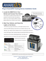
1.1 Diagnostic Tool Feature Locations
Figure 1-1 Features
4
2
3
1
15
13
14
5 6
7
11
12
10
9
8
1. Capacitive Touch Screen
2. Shortcut (S) Button (special functions)
3. Power Button (with backlit LED functions)
4. Audio Speaker
5. Stylus Storage
6. Scope Module M4 (removable)
7. Camera Lens
8. Communication and Power Jacks Cover
9. Head Phone Jack
10. Micro SD Card Slot
11. USB (universal serial bus) Jacks (2)
12. DC Power Supply Input Jack
13. Collapsible Stand
14. Battery Pack
15. Docking Station Connector

General Information Turning On/Off, and Emergency Shutdown
9
1.2 Power (Battery Pack/Charging)
1.2.1 Internal Battery Pack
The diagnostic tool (display unit) comes equipped with a rechargeable internal
battery pack that can be charged using the supplied AC power adapter. A fully
charged battery pack provides sufficient power for up to 5 hours of continuous
operation.
Battery Pack Charging
Use the supplied AC power adapter to charge the battery pack.
Insert the end of the AC power adapter cable into the DC power supply input jack
on the diagnostic tool, then connect the AC power adapter to an approved AC
power source.
IMPORTANT
Only use the supplied AC power adapter. Never connect the power
adapter to the diagnostic tool when the tool is communicating with a
vehicle.
Battery Status Indicator
An illuminated indicator is located in the power button, to indicate battery status and
charge level.
Three colors are used to show battery level and power status:
– Green (continuous on) - indicates either the battery is fully charged, or the
diagnostic tool is being powered by the AC power adapter.
– Orange (continuous on) - indicates the battery is charging.
– Red (continuous on) - indicates the battery is low (15% of capacity or less).
1.3 Turning On/Off, and Emergency
Shutdown
The following sections describe how to turn the diagnostic tool on and off, and
perform an emergency shutdown.
Before using the diagnostic tool, make sure the battery is fully charged, or is
connected to the AC power adapter. See Power (Battery Pack/Charging).
1.3.1 Turning On
Press and release the Power button (Figure 1-1) to switch the diagnostic tool on.
The system boots up, then opens the ShopStream Diagnostic Suite Home screen.
1.3.2 Turning Off
IMPORTANT
All vehicle communication must be terminated BEFORE turning off the
diagnostic tool. A warning message displays if you attempt to turn the
diagnostic tool off while communicating with the vehicle. Forcing a shut
down while communicating may lead to ECM problems on some
vehicles. Never disconnect the Compact Scan Module when the
diagnostic tool is communicating with the vehicle ECM.
Before turning the diagnostic tool off, it is highly recommended to back up personal
and saved data to a USB mass storage device on a regular basis to prevent loss in
the event of system corruption or hard disk drive failure, see Data Backup on
page 174.
z To turn off the diagnostic tool:
1. Navigate to the Home screen.
2. Select the Exit icon.
3. From the Windows desktop, open the Windows Start menu.
4. Select Shutdown.
Battery Status Indicator (modes)
Power Button Description
Turns the diagnostic tool on. See Battery Status Indicator for battery
status indicator information.

General Information Turning On/Off, and Emergency Shutdown
10
1.3.3 Emergency Shutdown
IMPORTANT
Using the emergency shutdown procedure while communicating with
the vehicle ECM may lead to ECM problems on some vehicles.
During normal operation, turn the diagnostic tool off using the Turning Off procedure
above. The emergency shutdown procedure should only be used as the last option,
if the diagnostic tool does not respond to navigation or control buttons or exhibits
erratic operation.
To perform an emergency shutdown:
1. Press and release the Power button.
The display screen will turn off and the LED backlit power button will turn red and
begin blinking.
2. Press and hold the Power button again, until the LED in the power button
stops blinking.
1.4 Shortcut (S) Button (Setup)
The Shortcut (S) button (Figure 1-2) is located on the front of the diagnostic tool,
and is a customizable button that can be set to perform various routine functions.
Figure 1-2
NOTE
You can open the Shortcut menu at anytime by pressing and holding the
Shortcut (S) button for three seconds.
Pressing the shortcut button (Figure 1-2) (when set to open the shortcut menu),
opens a slide-out menu which provides the following selectable icon options:
Icon Description
Screen
Capture Saves a bitmap image (screenshot) of the visible screen. For file
retrieval and management information, see
Viewing Saved Files on
page 161
.
Camera
Opens the camera application. See Camera (Taking Pictures) on
page 11
for additional information.
Keyboard
Opens the virtual keyboard. See Virtual Keyboard (Entering Text) on
page 14
for additional information.
Brightness
Opens the display brightness setting. Use multiple taps to toggle though
the brightness level settings.
Settings
Opens the Shortcut (S) button configuration menu.

General Information Camera (Taking Pictures)
11
1.4.1 Configure Shortcut (S) Button
This feature allows you to change the function of the Shortcut (S) button.
z To configure the Shortcut (S) button:
1. Press and release the Shortcut (S) button.
2. Select the Settings icon from the slide-out menu.
3. Choose the function you would like the Shortcut (S) button to perform when
pressed (Figure 1-3).
The current/active setting is indicated by a yellow highlight box.
Figure 1-3 Shortcut (S) button configuration menu
4. Select Cancel.
1.4.2 Advanced (menu selection)
The Advanced selection has no functionality under normal operating conditions,
and should ONLY be selected when directed to do so, by Snap-on customer
service.
Selecting Advanced displays the advanced diagnostic system information screen.
The system information and functions are ONLY used during system
troubleshooting, when requested by Snap-on customer service.
1.5 Camera (Taking Pictures)
1.5.1 Using the Camera
Selecting Camera from the Shortcut (S) button menu opens the camera
application. The touch screen becomes the view finder and is also used for
reviewing photographs that are taken. Icons on the touch screen are used to
operate the camera. The icons change depending on which camera function is
active:
Icon Description
Photo
Acts as a shutter to take a photograph of what is visible in the view finder,
which is the left-hand portion of the screen.
Gallery
Opens a thumbnail gallery of recently taken pictures.
Exit
Closes the camera application and returns to the previous screen.
Save
Displays after a picture is taken. Selecting saves the photograph and
returns to the view finder.
Delete
Displays after a picture is taken and in Gallery mode. Selecting discards
the photograph and returns to the previous screen.
Back
Displays in Gallery mode. Selecting returns to the previously viewed
screen.
Previous
Displays in Gallery mode. Selecting opens the picture prior to the current
image in the gallery.
Next
Displays in Gallery mode. Selecting opens the picture after the current
image in the gallery.

General Information Windows (Applicable Features / Operations)
12
z Taking pictures:
1. Press the Shortcut (S) Button and choose Camera from the menu.
2. Focus the image to be captured in the view finder.
3. Press the Photo icon.
The view finder now shows the captured picture.
4. Select Save to save the image, or Delete to delete it.
5. Select Exit from the live view to close the camera application.
1.5.2 Viewing Pictures
Photographs are stored on the hard drive and can be retrieved two ways:
From the Diagnostic Suite; select Data Manager from the Home screen, then open
the Camera Folder.
From the desktop; select ShopStream User > My Documents > ShopStream >
Camera Folder.
1.6 Windows (Applicable Features /
Operations)
The ShopStream Diagnostic Suite program runs on the Microsoft Windows 7
operating system. This section includes introductory information on some of the
Windows features and programs that are applicable with the operation of the
ShopStream Diagnostic Suite program.
Specific Windows features and instructions are beyond the scope of this manual,
please refer to Microsoft Windows 7 user documentation for additional information.
1.6.1 Wi-Fi Setup
The diagnostic tool uses Windows
®
7 embedded system software. Wi-Fi connection
is controlled through the Windows operating system.
The Wi-Fi connection instructions shown here are intended for quick reference only.
For Wi-Fi related instructions / troubleshooting that are outside the scope of these
instructions, visit Windows online support.
Wi-Fi connection allows you to:
• Access the Internet using the Windows web browser.
• Use built-in ShopStream Diagnostic Suite Repair Information applications (e.g.
Intelligent Diagnostics, SureTrack
®
, Tire and Wheel Service, TSBs, Oil Specs
and Resets, etc). Note: Repair Information applications are not available on all
models, are optional and vary by model.
• Receive diagnostic software updates
• Receive important product messages.
Connecting to Wi-Fi
NOTE
Whenever the diagnostic tool is turned on, Wi-Fi will automatically try to
connect to a network.
1. Turn on the diagnostic tool and allow Windows to bootup, then allow the
ShopStream Diagnostic Suite software to open.
After bootup if Wi-Fi is not automatically connected you will notice the Wi-Fi icon in
the System Tray (lower right side) is gray with an amber colored star (this indicates
Wi-Fi is not connected (shown below).
2. To connect to a network, click the Wi-Fi icon in the System Tray.

General Information Windows (Applicable Features / Operations)
13
The wireless network connection window opens (shown below).
3. Choose your Wireless Network from the list of available networks, then select
Connect.
NOTE
A password is required when choosing a protected network.
A wireless network connection progress window displays as the connection is being
made.
4. After the connection is successfully made, the Wi-Fi icon in the System Tray will
display as Connected (shown below).
The diagnostic tool is now connected to the Wi-Fi network.
NOTE
Wi-Fi performance varies depending on your wireless network equipment and
ISP.
1.6.2 Windows Taskbar
The standard Windows taskbar displays program icons that are currently running or
that you have pinned to the taskbar for quick access.
1.6.3 Windows Taskbar Notification Area
The notification area contains icons that provide active status and notifications of
selected programs. The notification area may contain standard Windows
application icons (e.g. Wireless Network Connection Status, Audio volume, etc.)
and specialized application icons designed for use only on this diagnostic tool (e.g.
ShopStream Update Tool and Virtual Keyboard).
For additional information on the ShopStream Update Tool and Virtual Keyboard,
see:
ShopStream Update Tool - ShopStream Update Tool (SST) on page 176
Virtual Keyboard - Virtual Keyboard (Entering Text) on page 14
1.6.4 Touch Screen and Stylus
The capacitive touch screen is used to control almost all the operations of the
diagnostic tool. Simply touch the screen with your finger, or use the capacitive
stylus to make a selection. The capacitive touch screen also provides you with
multi-touch gesture capabilities found on common surface touch devices. Most
operations are menu driven, which allows you to quickly locate the test, procedure,
or data that you need through a series of choices and questions. Detailed
descriptions of the menu structures are found in the sections for the various
functions.
For information on touch screen calibration, maintenance and stylus tip
replacement:
Touch screen calibration - see Calibrating the Touch Screen on page 18
Touch screen maintenance - see Cleaning on page 182
Stylus tip replacement - see Stylus Tip Replacement (Touch Screen) on page 186
My wireless connection 1
My wireless connection 2
My wireless connection 3
My wireless connection 4
My wireless connection 5
My wireless connection 6
My wireless connection 7
My wireless connection 1
My wireless connection 3
My wireless connection 4
My wireless connection 5
My wireless connection 6
My wireless connection 7
/