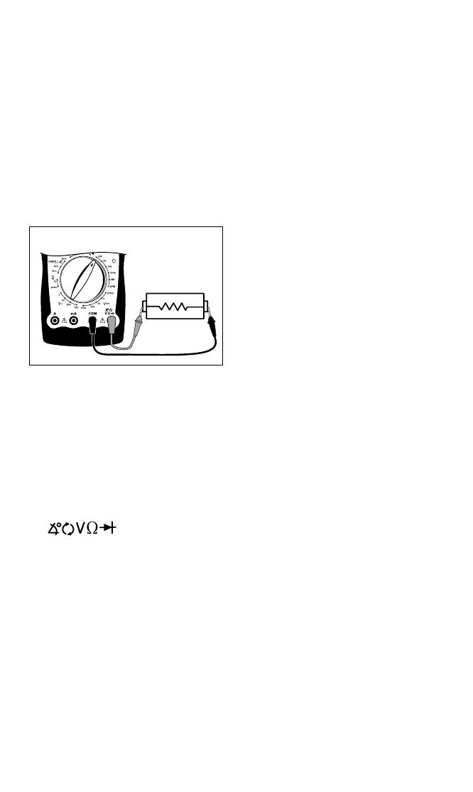
Actron CP7677 Operating instructions

Category
Multimeters
Type
Operating instructions
1
Index
Safety Precautions ......................................... 2
Vehicle Service Information ........................... 3
Visual Inspection ............................................ 3
Electrical Specifications ............................... 34
Warranty ..................................................... 104
1. Multimeter Basic Functions
Functions and Display Definitions ............ 4
Setting the Range ..................................... 6
Battery and Fuse Replacement................ 7
Measuring DC Voltage.............................. 8
Measuring AC Voltage.............................. 8
Measuring Resistance .............................. 9
Measuring DC Current.............................. 9
Testing for Continuity.............................. 10
Testing Diodes ........................................ 11
Measuring Engine RPM.......................... 11
Measuring Dwell ..................................... 12
2. Automotive Testing with the CP7677
General Testing ...................................... 13
- Testing Fuses ...................................... 13
- Testing Switches ................................. 13
- Testing Solenoids and Relays ............ 14
Starting / Charging System Testing ....... 15
- No Load Battery Test .......................... 15
- Engine Off Battery Current Draw ........ 15
CP7677
Auto
TroubleShooter
OPERATING
INSTRUCTIONS
- Cranking Voltage/Battery Load Test... 16
- Voltage Drops ...................................... 17
- Charging System Voltage Test ........... 18
Ignition System Testing .......................... 19
- Ignition Coil Testing ............................. 19
- Ignition System Wires.......................... 21
- Hall Effect Sensors/Switches .............. 22
- Magnetic Pick-Up Coils ....................... 23
- Reluctance Sensors ............................ 23
- Ignition Coil Switching Action.............. 24
Fuel System Testing ............................... 25
- Testing GM C-3 Mixture Control
Solenoid Dwell .................................... 25
- Measuring Fuel Injector Resistance ... 26
Testing Engine Sensors.......................... 27
- Oxygen (O
2
) Type Sensors ................. 27
- Temperature Type Sensors ................ 29
- Position Type Sensors –
Throttle and EGR Valve Position,
Vane Air Flow ...................................... 30
- Manifold Absolute Pressure (MAP) and
Barometric Pressure (BARO) Sensors 31
- Mass Air Flow (MAF) Sensors ............ 32
Instrucciones en español ....35
Instructions en français.......69
2
SAFETY GUIDELINES
TO PREVENT ACCIDENTS THAT COULD RESULT IN SERIOUS INJURY
AND/OR DAMAGE TO YOUR VEHICLE OR TEST EQUIPMENT,
CAREFULLY FOLLOW THESE SAFETY RULES AND TEST PROCEDURES
Always wear approved eye protection.
Always operate the vehicle in a well ventilated area. Do not inhale exhaust gases
– they are very poisonous!
Always keep yourself, tools and test equipment away from all moving or hot
engine parts.
Always make sure the vehicle is in park (Automatic transmission) or neutral
(manual transmission) and that the parking brake is firmly set. Block the drive
wheels.
Never lay tools on vehicle battery. You may short the terminals together causing
harm to yourself, the tools or the battery.
Never smoke or have open flames near vehicle. Vapors from gasoline and
charging battery are highly flammable and explosive.
Never leave vehicle unattended while running tests.
Always keep a fire extinguisher suitable for gasoline/electrical/chemical fires
handy.
Always use extreme caution when working around the ignition coil, distributor
cap, ignition wires, and spark plugs. These components contain High Voltage
when the engine is running.
Always turn ignition key OFF when connecting or disconnecting electrical
components, unless otherwise instructed.
Always follow vehicle manufacturer’s warnings, cautions and service procedures.
CAUTION:
Some vehicles are equipped with safety air bags. You
must
follow vehicle service
manual cautions when working around the air bag components or wiring. If the
cautions are not followed, the air bag may open up unexpectedly, resulting in personal
injury. Note that the air bag can still open up several minutes after the ignition key is
off (or even if the vehicle battery is disconnected) because of a special energy reserve
module.
All information, illustrations and specifications contained in this manual are based on the latest
information available from industry sources at the time of publication. No warranty (expressed
or implied) can be made for its accuracy or completeness, nor is any responsibility assumed by
Actron Manufacturing Co. or anyone connected with it for loss or damages suffered through
reliance on any information contained in this manual or misuse of accompanying product. Actron
Manufacturing Co. reserves the right to make changes at any time to this manual or accompa-
nying product without obligation to notify any person or organization of such changes.
3
Vehicle Service Manual Sources For Service
Information
The following is a list of sources to obtain vehicle service information for your specific
vehicle.
Contact your local Automotive Dealership Parts Department.
Contact local retail auto parts stores for aftermarket vehicle service information.
Contact your local library. Libraries often allow you to check-out automotive service
manuals.
Do a Thorough Visual Inspection
Do a thorough visual and hands-on underhood inspection before starting any
diagnostic procedure! You can find the cause of many problems by just looking,
thereby saving yourself a lot of time.
Has the vehicle been serviced
recently? Sometimes things get
reconnected in the wrong place, or
not at all.
Dont take shortcuts. Inspect hoses
and wiring which may be difficult to
see due to location.
Inspect the air cleaner and
ductwork for defects.
Check sensors and actuators for
damage.
Inspect ignition wires for:
- Damaged terminals.
- Split or cracked spark plug boots
- Splits, cuts or breaks in the ignition
wires and insulation.
Inspect all vacuum hoses for:
- Correct routing. Refer to vehicle
service manual, or Vehicle Emis-
sion Control Information(VECI)
decal located in the engine com-
partment.
- Pinches and kinks.
- Splits, cuts or breaks.
Inspect wiring for:
- Contact with sharp edges.
- Contact with hot surfaces, such as
exhaust manifolds.
- Pinched, burned or chafed insula-
tion.
- Proper routing and connections.
Check electrical connectors for:
- Corrosion on pins.
- Bent or damaged pins.
- Contacts not properly seated in
housing.
- Bad wire crimps to terminals.
4
11
Alligator Clip Adapters
Some multimeter tests and measurements are more easily done using
alligator clips instead of test prods. For these tests, push the crimp end of the
alligator clip onto the test prod. If the crimp on the alligator clip becomes loose,
then remove the alligator clip from the test prod and re-crimp using a pair of
pliers.
Section 1. Multimeter Basic Functions
Digital multimeters or DMMs have many special features and functions. This section
defines these features and functions, and explains how to use these functions to make
various measurements.
10
8
7
1
2
3
5
12
4
9
6
5
Functions and Display Definitions
1. ROTARY SWITCH
Switch is rotated to select a function.
2. DC VOLTS
This function is used for measuring DC
(Direct Current) Voltages in the range
of 0 to 1000V.
3. OHMS
This function is used for measuring the
resistance of a component in an elec-
trical circuit in the range of 0.1 to
20M. ( is the electrical symbol for
Ohms)
4.
DIODE CHECK / CONTINUITY TESTS
This function is used to check whether a
diode is good or bad. It is also used for
fast continuity checks of wires and ter-
minals. An audible tone will sound if a
wire and terminal are good.
5. HOLD
Press HOLD button to retain data on
display. In the hold mode, the "H" an-
nunciator is displayed.
6. TEST LEAD JACKS
BLACK Test Lead is al-
ways inserted in the COM
jack.
RED Test Lead is in-
serted in the jack corre-
sponding to the multim-
eter rotary switch setting.
8. DC AMPS
This function is used for measuring DC
(Direct Current) Amps in the range of 0
to 10A.
9. DWELL
This function is used for measuring
DWELL on distributor ignition systems,
and solenoids.
10. TACH
This function is used for measuring
engine speed (RPM).
11. ON/OFF
Press to turn power ON. Press again to
turn power OFF.
12. DISPLAY
Used to display all measurements and
multimeter information.
Low Battery If this symbol appears
in the lower left corner of the display,
then replace the inter-
nal 9V battery. (See
Fuse and Battery re-
placement on page 7.)
Overrange Indication
If 1 or -1 appears
on the left side of the
display, then the multi-
meter is set to a range
that is too small for the
present measurement
being taken. Increase
the range until this dis-
appears. If it does not
disappear after all the ranges for a
particular function have been tried, then
the value being measured is too large
for the multimeter to measure. (See
Setting the Range on page 6.)
Zero Adjustment
The multimeter will automatically zero on
the Volts, Amps and RPM functions.
Automatic Polarity Sensing
The multimeter display will show a minus (-)
sign on the DC Volts and DC Amps functions
when test lead hook-up is reversed.
Always connect TEST LEADS to the mul-
timeter before connecting them to the
circuit under test!!
7. AC VOLTS
This function is used for measuring AC
Voltages in the range of 0 to 750V.
DC VOLTS
AC VOLTS
DIODES
CONTINUITY
RPM
DWELL
OHMS
DC AMPS
6
Setting the Range
Two of the most commonly asked ques-
tions about digital multimeters are What
does Range mean? and How do I know
what Range the multimeter should be
set to?
What Does Range mean?
Range refers to the largest value the
multimeter can measure with the rotary
switch in that position. If the multimeter
is set to the 20V DC range, then the
highest voltage the multimeter can mea-
sure is 20V in that range.
EXAMPLE: Measuring Vehicle Battery
Voltage (See Fig. 1)
Now assume we set the multimeter to
the 2V range. (See Fig. 2)
The multimeter display now shows a 1
and nothing else. This means the multi-
meter is being overranged or in other
words the value being measured is larger
than the current range. The range should
be increased until a value is shown on
the display. If you are in the highest
range and the multimeter is still showing
that it is overranging, then the value
being measured is too large for the mul-
timeter to measure.
How do I know what Range the multi-
meter should be set to?
The multimeter should be set in the
lowest possible range without
overranging.
EXAMPLE: Measuring an unknown re-
sistance
Lets assume the multimeter is con-
nected to an engine coolant sensor with
unknown resistance. (See Fig. 3)
Fig. 2
Fig. 1
Lets assume the multimeter is con-
nected to the battery and set to the 20V
range.
The display reads 12.56. This means
there is 12.56V across the battery termi-
nals.
Fig. 3
Start by setting the multimeter to the
largest OHM range. The display reads
0.0 or a short circuit.
This sensor cant be shorted so reduce
the range setting until you get a value of
resistance.
At the 200K range the multimeter mea-
sured a value of 4.0. This means there is
4K of resistance across the engine
coolant sensor terminals. (See Fig. 4)
If we change the multimeter to the 20K
range (See Fig. 5) the display shows a
Red
Black
Red
Black
Black
Red
7
Fig. 4
Fig. 5
value of
3.87K. The
actual value of
resistance is
3.87K and not
4K that was
measured in
the 200K
range. This is
very important
because if the
manufacturer
specifications
say that the
sensor should
read 3.8-3.9K
at 70°F then on
the 200K
range the sensor would be defective, but
at the 20K range it would test good.
Now set the multimeter to the 2K range.
(See Fig. 6) The
display will indi-
cate an
overrange con-
dition because
3.87K is larger
than 2K.
This example
shows that by
decreasing the
range you in-
crease the ac-
curacy of your
measurement.
When you
change the
range, you
change the lo-
cation of the decimal point. This changes
Fig. 6
the accuracy of the measurement by ei-
ther increasing or decreasing the number
of digits after the decimal point.
Battery and Fuse
Replacement
Important: A 9 Volt battery must be in-
stalled before using the digital multim-
eter. (see procedure below for installa-
tion)
Battery Replacement
1. Turn multimeter OFF.
2. Remove test leads from
multimeter.
3. Remove screw from battery
cover.
4. Remove battery cover.
5. Install a new 9 Volt battery.
6. Re-assemble multimeter.
Fuse Replacement
1. Turn multimeter OFF.
2. Remove test leads from
multimeter.
3. Remove rubber holster.
4. Remove screw from battery
cover, battery cover, and battery.
5. Remove screws from back of
multimeter.
6. Remove back cover.
7. Remove fuse.
8. Replace fuse with same size and
type as originally installed.
Use a 1/4" x 1-1/4", 10A, 250V, fast
acting fuse or a 5mm x 20mm
315mA, 250V fast acting fuse.
9. Re-assemble multimeter.
8
Measuring DC Voltage
This multimeter can be used to measure
DC voltages in the range from 0 to 1000V.
You can use this multimeter to do any DC
voltage measurement called out in the
vehicle service manual. The most com-
mon applications are measuring voltage
drops, and checking if the correct voltage
arrived at a sensor or a particular circuit.
To measure DC Voltages (see Fig. 7):
6. View reading on display - Note
range setting for correct units.
NOTE: 200mV = 0.2V
Measuring AC Voltage
This multimeter can be used to measure
AC voltages in the range from 0 to 750V.
To measure AC Voltages (see Fig. 8):
Fig. 7
1. Insert BLACK test lead into COM
test lead jack.
2. Insert RED test lead into
test lead jack.
3. Connect RED test lead to positive
(+) side of voltage source.
4. Connect BLACK test lead to nega-
tive (-) side of voltage source.
NOTE: If you dont know which side
is positive (+) and which side is nega-
tive (-), then arbitrarily connect the
RED test lead to one side and the
BLACK to the other. The multimeter
automatically senses polarity and will
display a minus (-) sign when nega-
tive polarity is measured. If you
switch the RED and BLACK test
leads, positive polarity will now be
indicated on the display. Measuring
negative voltages causes no harm
to the multimeter.
5. Turn multimeter rotary switch to
desired voltage range.
If the approximate voltage is unknown,
start at the largest voltage range and
decrease to the appropriate range as
required. (See Setting the Range on
page 6)
1. Insert BLACK test lead into COM
test lead jack.
2. Insert RED test lead into
test lead jack.
3. Connect RED test lead to one side
of voltage source.
4. Connect BLACK test lead to other
side of voltage source.
5. Turn multimeter rotary switch to
desired voltage range.
If the approximate voltage is un-
known, start at the largest voltage
range and decrease to the appropri-
ate range as required. (See Setting
the Range on page 6)
6. View reading on display - Note
range setting for correct units.
NOTE: 200mV = 0.2V
Red
Black
Fig. 8
Red
Black
9
Fig. 9
ments, polarity is not important. The
test leads just have to be connected
across the component.
6. Turn multimeter rotary switch to
desired OHM range.
If the approximate resistance is un-
known, start at the largest OHM
range and decrease to the appropri-
ate range as required. (See Setting
the Range on page 6)
7. View reading on display - Note
range setting for correct units.
NOTE: 2K = 2,000; 2M =
2,000,000
If you want to make precise resis-
tance measurements, then subtract
the test lead resistance found in Step
4 above from the display reading in
Step 7. It is a good idea to do this for
resistance measurements less than
10.
Measuring DC Current
This multimeter can be used to measure
DC current in the range from 0 to 10A. If
the current you are measuring exceeds
10A, the internal fuse will blow (see Fuse
Replacement on page 7). Unlike voltage
and resistance measurements where the
multimeter is connected across the com-
ponent you are testing, current measure-
ments must be made with the multimeter
in series with the component. Isolating
current drains and short circuits are some
DC Current applications.
To measure DC Current (see Figs. 10 &
11):
1. Insert BLACK test lead into COM
test lead jack.
2. Insert RED test lead into "10A"
test lead jack or "mA" test lead
jack.
3. Disconnect or electrically open cir-
cuit where you want to measure
current.
This is done by:
Disconnecting wiring harness.
Disconnecting wire from screw-on
type terminal.
Unsolder lead from component if
Red Black
Unknown
Resistance
Measuring Resistance
Resistance is measured in electrical
units called ohms (). The digital multi-
meter can measure resistance from 0.1
to 20M or (20,000,000 ohms). Infinite
resistance is shown with a 1 on the left
side of display (See Setting the Range
on page 6). You can use this multimeter
to do any resistance measurement called
out in the vehicle service manual. Test-
ing ignition coils, spark plug wires, and
some engine sensors are common uses
for the OHMS () function.
To measure Resistance (see Fig. 9):
1. Turn circuit power OFF.
To get an accurate resistance mea-
surement and avoid possible damage
to the digital multimeter and electrical
circuit under test, turn off all electrical
power in the circuit where the resis-
tance measurement is being taken.
2. Insert BLACK test lead into COM
test lead jack.
3. Insert RED test lead into
test lead jack.
4. Turn multimeter rotary switch to
200
range.
Touch RED and BLACK multimeter
leads together and view reading on
display.
Display should read typically 0.2 to
1.5.
If display reading was greater than
1.5, check both ends of test leads
for bad connections. If bad connec-
tions are found, replace test leads.
5. Connect RED and BLACK test
leads across component where
you want to measure resistance.
When making resistance measure-
10
working on printed circuit boards.
Cut wire if there is no other pos-
sible way to open electrical circuit.
4. Connect RED test lead to one side
of disconnected circuit.
5. Connect BLACK test lead to re-
maining side of disconnected cir-
cuit.
6. Turn multimeter rotary switch to
10A DC position, or 200mA posi-
tion.
7. View reading on display.
If minus (-) sign appears on display,
then reverse RED and BLACK test
leads.
Testing for Continuity
Continuity is a quick way to do a resis-
tance test to determine if a circuit is
open or closed. The multimeter will beep
when the circuit is closed or shorted, so
you dont have to look at the display.
Continuity checks are usually done when
checking for blown fuses, switch opera-
tion, and open or shorted wires.
To measure Continuity (see Fig. 12):
Fig. 12
Black
Red
Fig. 10
Black
Red
Electrical
Device
DC
Voltage
Source
Fig. 11
Black
Red
Electrical
Device
DC
Voltage
Source
1. Insert BLACK test lead into COM
test lead jack.
2. Insert RED test lead into
test lead jack.
3. Turn multimeter rotary switch to
function.
4. Touch RED and BLACK test leads
together to test continuity.
Listen for tone to verify proper op-
eration.
5. Connect RED and BLACK test
leads across component where
you want to check for continuity.
Listen for tone:
If you hear tone Circuit is closed
or shorted.
If you dont hear tone Circuit is
open.
11
Fig. 13
7. Switch RED and BLACK test leads
and repeat Step 6.
8. Test Results
If the display showed:
A voltage drop of 0 volts in both
directions, then the diode is shorted
and needs to be replaced.
A 1 appears in both directions,
then the diode is an open circuit
and needs to be replaced.
The diode is good if the display
reads around 0.5V0.7V in one di-
rection and a 1 appears in the
other direction indicating the multi-
meter is overranged.
Measuring Engine RPM
RPM refers to revolutions per minute.
When using this function you must multi-
ply the display reading by 10 to get actual
RPM. If display reads 200 and the multim-
eter is set to 6 cylinder RPM, the actual
engine RPM is 10 times 200 or 2000 RPM.
To measure Engine RPM (see Fig. 14):
Testing Diodes
A diode is an electrical component that
allows current to only flow in one direc-
tion. When a positive voltage, generally
greater than 0.7V, is applied to the an-
ode of a diode, the diode will turn on and
allow current to flow. If this same volt-
age is applied to the cathode, the diode
would remain off and no current would
flow. Therefore, in order to test a diode,
you must check it in both directions (i.e.
anode-to-cathode, and cathode-to-an-
ode). Diodes are typically found in alter-
nators on automobiles.
Performing Diode Test (see Fig. 13):
Typical
Ignition
Coil
Ground
Black
Red
Fig. 14
Anode
Cathode
Black
Red
1. Insert BLACK test lead into COM
test lead jack.
2. Insert RED test lead into
test lead jack.
3. Connect RED test lead to TACH
(RPM) signal wire.
If vehicle is DIS (Distributorless
Ignition System), then connect RED
test lead to the TACH signal wire
going from the DIS module to the
vehicle engine computer. (refer to
vehicle service manual for location
of this wire)
For all vehicles with distributors,
1. Insert BLACK test lead into COM
test lead jack.
2. Insert RED test lead into
test lead jack.
3. Turn multimeter rotary switch to
function.
4. Touch RED and BLACK test leads
together to test continuity.
Check display should reset to 0.00.
5. Disconnect one end of diode from
circuit.
Diode must be totally isolated from
circuit in order to test its functional-
ity.
6. Connect RED and BLACK test
leads across diode and view dis-
play.
Display will show one of three things:
A typical voltage drop of around
0.7V.
A voltage drop of 0 volts.
A 1 will appear indicating the mul-
timeter is overranged.
12
connect RED test lead to negative
side of primary ignition coil. (refer
to vehicle service manual for loca-
tion of ignition coil)
4. Connect BLACK test lead to a good
vehicle ground.
5. Turn multimeter rotary switch to
correct CYLINDER selection.
6. Measure engine RPM while engine
is cranking or running.
7. View reading on display.
Remember to multiply display read-
ing by 10 to get actual RPM.
If display reads 200, then actual en-
gine RPM is 10 times 200 or 2000
RPM.
Measuring Dwell
Dwell measuring was extremely impor-
tant on breaker point ignition systems of
the past. It referred to the length of time,
in degrees, that the breaker points re-
mained closed, while the camshaft was
rotating. Todays vehicles use electronic
ignition and dwell is no longer adjust-
able. Another application for dwell is in
testing the mixture control solenoid on
GM feedback carburetors.
To measure Dwell (see Fig. 15):
Ground
Black
Red
Fig. 15
Typical
Ignition
Coil
1. Insert BLACK test lead into COM
test lead jack.
2. Insert RED test lead into
test lead jack.
3. Connect RED test lead to DWELL
signal wire.
If measuring DWELL on breaker
point ignition systems, connect
RED test lead to negative side of
primary ignition coil. (refer to ve-
hicle service manual for location of
ignition coil)
If measuring DWELL on GM mix-
ture control solenoids, connect
RED test lead to ground side or
computer driven side of solenoid.
(refer to vehicle service manual for
solenoid location)
If measuring DWELL on any arbi-
trary ON/OFF device, connect RED
test lead to side of device that is
being switched ON/OFF.
4. Connect BLACK test lead to a good
vehicle ground.
5. Turn multimeter rotary switch to
correct DWELL CYLINDER posi-
tion.
6. View reading on display.
13
Section 2. Automotive Testing
The digital multimeter is a very useful
tool for trouble-shooting automotive elec-
trical systems. This section describes
how to use the digital multimeter to test
the starting and charging system, igni-
tion system, fuel system, and engine
sensors. The digital multimeter can also
be used for general testing of fuses,
switches, solenoids, and relays.
General Testing
The digital multimeter can be used to
test fuses, switches, solenoids, and re-
lays.
Testing Fuses
This test checks to see if a fuse is blown.
You can use this test to check the internal
fuses inside the digital multimeter.
To test Fuses (see Fig. 16):
If you hear tone - Fuse is good.
If you dont hear tone - Fuse is
blown and needs to be replaced.
NOTE: Always replace blown fuses
with same type and rating.
Testing Switches
This test checks to see if a switch
Opens and Closes properly.
To test Switches (see Fig. 17):
Fig. 17
Red
Typical "Push"
Button Switch
1. Insert BLACK test lead into COM
test lead jack.
2. Insert RED test lead into
test lead jack.
3. Turn multimeter rotary switch to
function.
4. Touch RED and BLACK test leads
together to test continuity.
Listen for tone to verify proper op-
eration.
5. Connect BLACK test lead to one
side of switch.
6. Connect RED test lead to other
side of switch.
Listen for tone:
If you hear tone - The switch is
closed.
If you dont hear tone - The switch
is open.
7. Operate switch.
Listen for tone:
1. Insert BLACK test lead into COM
test lead jack.
2. Insert RED test lead into
test lead jack.
3. Turn multimeter rotary switch to
function.
4. Touch RED and BLACK test leads
together to test continuity.
Listen for tone to verify proper op-
eration.
5. Connect RED and BLACK test
leads to opposite ends of fuse.
Listen for tone:
Fig. 16
Red
Black
Fuse
Black
14
If you hear tone - The switch is
closed.
If you dont hear tone - The switch
is open.
8. Repeat Step 7 to verify switch op-
eration.
Good Switch:
Tone turns ON and
OFF as you operate switch.
Bad Switch:
Tone always ON or tone
always OFF as you operate switch.
4. Connect BLACK test lead to one
side of coil.
5. Connect RED test lead to other
side of coil.
6. View reading on display.
Typical solenoid / relay coil resis-
tances are 200 or less.
Refer to vehicle service manual for
your vehicles resistance range.
7. Test Results
Good Solenoid / Relay Coil:
Display
in Step 6 is within manufacturers
specification.
Bad Solenoid / Relay Coil:
Display in Step 6 is not within manu-
facturers specifications.
Display reads overrange on every
ohms range indicating an open cir-
cuit.
NOTE: Some relays and solenoids
have a diode placed across the coil.
To test this diode see Testing Di-
odes on page 11.
1. Insert BLACK test lead into COM
test lead jack.
2. Insert RED test lead into
test lead jack.
3. Turn multimeter rotary switch to
200
function.
Most solenoids and relay coil resis-
tances are less than 200. If meter
overranges, turn multimeter rotary
switch to next higher range. (see
Setting the Range on page 6)
This test checks to see if a solenoid or
relay have a broken coil. If the coil tests
good, it is still possible that the relay or
solenoid are defective. The relay can
have contacts that are welded or worn
down, and the solenoid may stick when
the coil is energized. This test does not
check for those potential problems.
To test Solenoids and Relays (see Fig.
18):
Relay or
Solenoid
Red
Black
Fig. 18
Testing Solenoids and Relays
15
Starting/Charging System Testing
The starting system turns over the engine. It consists of the battery, starter motor,
starter solenoid and/or relay, and associated wiring and connections. The charging
system keeps the battery charged when the engine is running. This system consists
of the alternator, voltage regulator, battery, and associated wiring and connections.
The digital multimeter is a useful tool for checking the operation of these systems.
No Load Battery Test
Before you do any starting/charging sys-
tem checks, you must first test the bat-
tery to make sure it is fully charged.
Test Procedure (see Fig. 19):
Fig. 19
Black
Red
1. Turn Ignition Key OFF.
2. Turn ON headlights for 10 sec-
onds to dissipate battery surface
charge.
3. Insert BLACK test lead into COM
test lead jack.
4. Insert RED test lead into
test lead jack.
5. Disconnect positive (+) battery
cable.
6. Connect RED test lead to positive
(+) terminal of battery.
7.
Connect BLACK test lead to nega-
tive (-) terminal of battery.
8. Turn multimeter rotary switch to
20V DC range.
9. View reading on display.
10.Test Results.
Compare display reading in Step 9
with the following chart.
Percent
Voltage Battery is Charged
12.60V
or greater 100%
12.45V 75%
12.30V 50%
12.15V 25%
If battery is not 100% charged, then
charge it before doing anymore starting/
charging system tests.
Engine Off Battery
Current Draw
This test measures the amount of cur-
rent being drawn from the battery when
the ignition key and engine are both off.
This test helps to identify possible
sources of excessive battery current
drain, which could eventually lead to a
dead battery.
1. Turn Ignition Key and all accesso-
ries OFF.
Make sure trunk, hood, and dome
lights are all OFF.
(See Fig. 20)
2. Insert BLACK test lead into COM
test lead jack.
3. Insert RED test lead into "A" (or
"mA") test lead jack.
Black
Red
Fig. 20
16
4. Disconnect positive (+) battery
cable.
5. Connect RED test lead to positive
(+) battery terminal.
6. Connect BLACK test lead to posi-
tive (+) battery cable.
NOTE: Do not start vehicle during this
test, because multimeter damage may
result.
7. Turn multimeter rotary switch to
10A DC (or 200 mA) position.
8. View reading on display.
Typical current draw is 100mA.
(1mA = 0.001A)
Refer to vehicle service manual for
manufacturers specific Engine Off
Battery Current Draw.
NOTE: Radio station presets and
clocks are accounted for in the 100mA
typical current draw.
9. Test Results.
Normal Current Draw:
Display read-
ing in Step 8 is within manufacturers
specifications.
Excessive Current Draw:
- Display reading in Step 8 is well out-
side manufacturers specifications.
- Remove Fuses from fuse box one
at a time until source of excessive
current draw is located.
- Non-Fused circuits such as head-
lights, relays, and solenoids should
also be checked as possible cur-
rent drains on battery.
- When source of excessive current
drain is found, service as necessary.
Cranking Voltage -
Battery Load Test
This test checks the battery to see if it is
delivering enough voltage to the starter
motor under cranking conditions.
Test Procedure (see Fig. 21):
1. Disable ignition system so vehicle
wont start.
Disconnect the primary of the igni-
tion coil or the distributor pick-up coil
or the cam/crank sensor to disable
the ignition system. Refer to vehicle
service manual for disabling proce-
dure.
2. Insert BLACK test lead into COM
test lead jack.
3. Insert RED test lead into
test lead jack.
4. Connect RED test lead to positive
(+) terminal of battery.
5.
Connect BLACK test lead to nega-
tive (-) terminal of battery.
6. Turn multimeter rotary switch to
20V DC range.
7. Crank engine for 15 seconds con-
tinuously while observing display.
8. Test Results.
Compare display reading in Step 7
with chart below.
Voltage Temperature
9.6V or greater70 °F and Above
9.5V 60 °F
9.4V 50 °F
9.3V 40 °F
9.1V 30 °F
8.9V 20 °F
8.7V 10 °F
8.5V 0 °F
If voltage on display corresponds to
above voltage vs. temperature chart,
then cranking system is normal.
If voltage on display does not corre-
spond to chart, then it is possible that
the battery, battery cables, starting sys-
tem cables, starter solenoid, or starter
motor are defective.
Fig. 21
Red Black
17
If multimeter overranges, turn multim-
eter rotary switch to the 2V DC range.
(See Setting the Range on page 6)
6. Crank engine until steady reading
is on display.
Record results at each point as
displayed on multimeter.
Repeat Step 4 & 5 until all points
are checked.
7. Test Results
Estimated Voltage Drop of Starter
Circuit Components
Component Voltage
Switches 300mV
Wire or Cable 200mV
Ground 100mV
Battery Cable
Connectors 50mV
Connections 0.0V
Compare voltage readings in Step
6 with above chart.
If any voltages read high, inspect com-
ponent and connection for defects.
If defects are found, service as
necessary.
Voltage Drops
This test measures the voltage drop across
wires, switches, cables, solenoids, and
connections. With this test you can find
excessive resistance in the starter sys-
tem. This resistance restricts the amount
of current that reaches the starter motor
resulting in low battery load voltage and a
slow cranking engine at starting.
Test Procedure (see Fig. 22):
1. Disable ignition system so vehicle
wont start.
Disconnect the primary of the igni-
tion coil or the distributor pick-up coil
or the cam/crank sensor to disable
the ignition system. Refer to vehicle
service manual for disabling proce-
dure.
2. Insert BLACK test lead into COM
test lead jack.
3. Insert RED test lead into
test lead jack.
4. Connect test leads.
Refer to Typical Cranking Voltage
Loss Circuit (Fig. 22).
Connect RED and BLACK test leads
alternately between 1 & 2, 2 & 3, 4 &
5, 5 & 6, 6 & 7, 7 & 9, 8 & 9, and 8 &
10.
5. Turn multimeter rotary switch to
200mV DC range.
1
10
2
4
5
6 8
7
7
9
8
9
6
2
4
5
3
3
Red Black
Fig. 22 Typical Cranking Voltage
Loss Circuit
Solenoid
This is a representative sample of
one type of cranking circuit. Your
vehicle may use a different circuit
with different components or
locations. Consult your vehicle
service manual.
Starter
18
8. Open throttle and Hold engine
speed (RPM) between 1800 and
2800 RPM.
Hold this speed through Step 11 -
Have an assistance help hold speed.
9. View reading on display.
Voltage reading should not change
from Step 7 by more than 0.5V.
10. Load the electrical system by turn-
ing on the lights, windshield wip-
ers, and setting the blower fan on
high.
11.View reading on display.
Voltage should not drop down below
about 13.0V.
12.Shut off all accessories, return
engine to curb idle and shut off.
13.Test Results.
If voltage readings in Steps 7, 9,
and 11 were as expected, then
charging system is normal.
If any voltage readings in Steps 7,
9, and 11 were different then shown
here or in vehicle service manual,
then check for a loose alternator
belt, defective regulator or alterna-
tor, poor connections, or open al-
ternator field current.
Refer to vehicle service manual for
further diagnosis.
This test checks the charging system to
see if it charges the battery and pro-
vides power to the rest of the vehicles
electrical systems (lights, fan, radio etc).
Test Procedure (see Fig. 23):
Fig. 23
Red Black
1. Insert BLACK test lead into COM
test lead jack.
2. Insert RED test lead into
test lead jack.
3. Connect RED test lead to positive
(+) terminal of battery.
4.
Connect BLACK test lead to nega-
tive (-) terminal of battery.
5. Turn multimeter rotary switch to
20V DC range.
6. Start engine - Let idle.
7. Turn off all accessories and view
reading on display.
Charging system is normal if dis-
play reads 13.2 to 15.2 volts.
If display voltage is not between
13.2 to 15.2 volts, then proceed to
Step 13.
Charging System Voltage Test
19
Ignition System Testing
The ignition system is responsible for providing the spark that ignites the fuel in the cylinder.
Ignition system components that the digital multimeter can test are the primary and
secondary ignition coil resistance, spark plug wire resistance, hall effect switches/sensors,
reluctance pick-up coil sensors, and the switching action of the primary ignition coil.
Ignition Coil Testing
This test measures the resistance of the
primary and secondary of an ignition
coil. This test can be used for
distributorless ignition systems (DIS)
provided the primary and secondary ig-
nition coil terminals are easily acces-
sible.
Test Procedure:
1. If engine is HOT let it COOL down
before proceeding.
2. Disconnect ignition coil from ig-
nition system.
3. Insert BLACK test lead into COM
test lead jack (see Fig. 24).
7. Connect test leads.
Connect RED test lead to primary
ignition coil positive (+) terminal.
Connect BLACK test lead to primary
ignition coil negative (-) terminal.
Refer to vehicle service manual for
location of primary ignition coil ter-
minals.
8. View reading on display.
Subtract test lead resistance found
in Step 6 from above reading.
9. If vehicle is DIS, repeat Steps 7
and 8 for remaining ignition coils.
Typical Cylindrical
Ignition Coil
BlackRed
Primary
Coil
Secondary
Coil
Fig. 25
Typical Cylindrical
Ignition Coil
Black
Secondary
Coil
Primary
Coil
Red
4. Insert RED test
lead into
test
lead jack.
5. Turn multimeter
rotary switch to
200
range.
6. Touch RED and
BLACK multim-
eter leads to-
gether and view
reading on dis-
play.
10.Test Results - Pri-
mary Coil
Typical resistance
range of primary
ignition coils is 0.3
- 2.0.
Refer to vehicle
service manual
for your vehicles
resistance range.
11.Turn multimeter
rotary switch to
200K
range (see
Fig. 25).
Fig. 24
20
12.Move RED test lead to secondary
ignition coil terminal.
Refer to vehicle service manual for
location of secondary ignition coil
terminal.
Verify BLACK test lead is con-
nected to primary ignition coil nega-
tive (-) terminal.
13.View reading on display.
14.If vehicle is DIS, repeat Steps 12
and 13 for remaining ignition coils.
15.Test Results - Secondary Coil
Typical resistance range of sec-
ondary ignition coils is 6.0 - 30.0K.
Refer to vehicle service manual for
your vehicles resistance range.
16.Repeat test procedure for a HOT
ignition coil.
NOTE: It is a good idea to test
ignition coils when they are both hot
and cold, because the resistance of
the coil could change with tempera-
ture. This will also help in diagnosing
intermittent ignition system prob-
lems.
17.Test Results - Overall
Good Ignition Coil:
Resistance read-
ings in Steps 10, 15 and 16 were
within manufacturers specification.
Bad Ignition Coil:
Resistance read-
ings in Steps 10, 15 and 16 are not
within manufacturers specification.
  • Page 1 1
  • Page 2 2
  • Page 3 3
  • Page 4 4
  • Page 5 5
  • Page 6 6
  • Page 7 7
  • Page 8 8
  • Page 9 9
  • Page 10 10
  • Page 11 11
  • Page 12 12
  • Page 13 13
  • Page 14 14
  • Page 15 15
  • Page 16 16
  • Page 17 17
  • Page 18 18
  • Page 19 19
  • Page 20 20
  • Page 21 21
  • Page 22 22
  • Page 23 23
  • Page 24 24
  • Page 25 25
  • Page 26 26
  • Page 27 27
  • Page 28 28
  • Page 29 29
  • Page 30 30
  • Page 31 31
  • Page 32 32
  • Page 33 33
  • Page 34 34

Actron CP7677 Operating instructions

Category
Multimeters
Type
Operating instructions

Ask a question and I''ll find the answer in the document

Finding information in a document is now easier with AI