Page is loading ...

4902 TrueAlert
®
Ceiling-Mount and
Wall-Mount Speaker
Installation Instructions
2008, 2012 Tyco Fire Protection Products. All rights reserved.
Specifications and other information shown were current as of publication, and are subject to change without notice.
TYCO, SIMPLEX, and the product names listed in this material are marks and/or registered marks. Unauthorized use is strictly prohibited.
Suffix “C” or “CA” following an eight-digit product ID number denotes ULC-listed product.
574-765
Rev. E
Cautions and Warnings
DO NOT INSTALL ANY SIMPLEX
®
PRODUCT THAT APPEARS DAMAGED. Upon unpacking your Simplex product, inspect the contents of
the carton for shipping damage. If damage is apparent, immediately file a claim with the carrier and notify an authorized Simplex product supplier.
ELECTRICAL HAZARD - Disconnect electrical field power when making any internal adjustments or repairs. All repairs should be performed by a
representative or authorized agent of your local Simplex product supplier. Even with electrical power removed, some notification appliances store a high
voltage charge. The high voltage can cause injury or death. DO NOT TOUCH EXPOSED CIRCUITRY.
STATIC HAZARD - Static electricity can damage components. Handle as follows: 1. Ground yourself before opening or installing components.
2. Prior to installation, keep components wrapped in anti-static material at all times.
TrueAlert Speaker Operation
TrueAlert Speakers (see Figures 1 and 2) are notification appliances that reproduce audio signals when activated from a Simplex 4100 fire alarm control
panel (FACP), Simplex 4003 voice control panel, or a UL-listed FACP with compatible audio NAC interface. When the notification appliance emits
sound, it indicates the possibility of an emergency situation that requires your immediate attention.
The TrueAlert speaker is a two-wire appliance that operates only on a standard audio NAC channel (4100/4003) to reproduce amplified analog audio signals.
Input can be either 25 VRMS or 70.7 VRMS that can be selected via a jumper to one of four available audible power wattage levels (¼ W, ½ W, 1W, 2W).
_______________________________________________________________________________________________________________________________
TrueAlert Speaker Wiring
Caution: Connect the wiring to the terminals as shown. Do not loop the wires under the terminals. Break wire runs to provide supervision of the
connections. Do not bring the conduit through the rear of the electrical box. Strip the lead insulation to a maximum of 3/8 inch.
Note: The ceiling- and wall-mount speaker wattage jumper settings and wiring connections are identical. The wall-mount speaker is illustrated below.
1. At the enclosure box, connect the wires to the SPKR + and SPKR - terminals at the rear of the speaker unit. Torque the terminal block screws to 12-15
in/lbs. to ensure proper continuity. See Figure 3.
2. Ensure that the correct polarity is maintained for each unit.
3. Ensure that the RMS value of the connected audio circuit matches the RMS value of the connected speaker. An incorrect tap setting may damage the
speaker. Configure the speaker wattage setting using Table 1. The factory default setting for the speaker is J1 to Tap E (25 VRMS, 0.5 W).
4. The maximum normal supervisory voltage is 40 VDC.
5. Audio NAC wiring must be a twisted pair (TWP).
FigureTag FD4-765-02
.
______________________________________________________________________________________________________________________________________________________________________________________________________
Mounting the TrueAlert Wall-Mount Speaker
See Figure 4 for mounting the TrueAlert wall-mount speaker to the enclosure box. When surface mounting the speaker, either the 4905-9941 or
4905-9942, a TrueAlert surface mount skirt is recommended. Refer to the 4905 TrueAlert Skirt Installation Instructions (574-790) for this mounting
application.
Caution: Do not bring the conduit through the rear of the electrical box.
1. Tighten mounting screws snugly (do not overtighten). Torque mounting screws to 5-7 in/lbs.
2. For semi-flush mounting, install the box either flush with the wall or with a maximum recess of ¼-inch.
SPKR - TERMINAL
SPKR + TERMINAL
JUMPER J1
(Shown tapped to G,
the 25 VRMS, 2 W
Position)
See Table 2
BLK
SPKR -
SPKR +
RED
BLK
SPKR -
SPKR +
RED
25 VRMS or
70.7 VRMS
AUDIO INPUT
FROM
4100/4003
(See Notes)
Notes:
1. Refer to the field wiring diagrams supplied with the
4100/4003 for additional NAC wiring information.
2. Notification appliances are rated per individual nameplate
label.
3. Maintain correct polarity on terminal connections. Do not
loop wires under terminals.
4. All NAC wiring connections are supervised and power
limited.
Figure 3. TrueAlert Speaker Wiring
IF THIS IS THE
LAST
APPLIANCE ON
THE CIRCUIT,
CONNECT THE
EOLR
(
See Notes
)
TB1 TERMINALS
ACCEPT
2 WIRES: #12 - #18 AWG
TWP
(See Note 3 listed below)
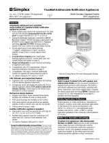
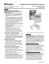
Figure 1. TrueAlert
Wall-Mount Speaker
4902-9716 – Red
4902-9717 – White
Figure 2. TrueAlert
Ceiling-Mount
Speaker
4902-9721 – White
FigureTag FD4-765-01
Note: Unlike other TrueAlert peripherals, the speaker does not
support the addressable features of the TrueAlert comm
channel. The TrueAlert speaker is non-addressable and
does not support audio wire T-tapping. Ceiling mount
speakers are not intended for use in air-handling spaces.
TrueAlert Wall-Mount Speaker Configuration (Rear View)
Fi
g
ureTa
g
FD4-765-03
Voltage
Jumper
Position
Wattage
Setting
Voltage
Jumper
Position
Wattage
Setting
70.7VRMS
J1 to Tap A 0.25
25.0VRMS
J1 to Tap D 0.25
J1 to Tap B 0.50 J1 to Tap E 0.50
J1 to Tap C 1.00 J1 to Tap F 1.00
J1 to Tap D 2.00 J1 to Tap G 2.00
Table 1. TrueAlert Speaker Jumper Settings

574-765
Rev. E
Mounting the TrueAlert Wall-Mount Speaker, Continued
FigureTag FD4-765-04
________________________________________________________________________________________________________________________________________________________________________________________________________
Mounting the TrueAlert Ceiling-Mount Speaker
See Figure 5 for mounting the TrueAlert ceiling-mount speaker to the enclosure box.
Caution: Do not bring the conduit through the rear of the electrical box.
1. Tighten mounting screws snugly (do not over tighten). Torque mounting screws to 5-7 in/lbs.
2. For semi-flush mounting, install the box either flush with the ceiling or with a maximum ¼-inch recess.
Notes:
1. The TrueAlert ceiling-mount speaker attaches directly to a standard 4-inch square electrical box (not supplied)
semi-flush mounted or surface mounted.
2. Ensure the correct orientation of the box with the extension in relation to the location of the mounting screws.
3. For installation in plaster or concrete ceiling, mount the box with extension flush or with maximum recess of ¼-inch. For a suspended ceiling, use
a suitable bridge that rests on the tile to support the box with the extension.
Figure 5. 4902-9721 TrueAlert Ceiling-Mount Speaker Mounting
___________________________________________________________________________________________________________________________________________________________________________________
Speaker Sound Pressure Level Measurements
Refer to Table 2 for sound pressure level measurements for each power tap setting.
Note: Reverberant
dBA measurements are a minimum UL rating based on the sound power level measurements made in UL’s reverberant test chamber.
Table 2. Wall-Mount and Ceiling-Mount Speaker Sound Pressure Level Measurements
Voltage
in
VRMS
Jumper J1 to
Tap
Tap Setting in
Watts
Sound Pressure Level Measurement (dBA) Sound Pressure Level Measurement (dBA)
Reverberant Room at Ten Feet Per UL1480
(Wall-Mount) (See Note)
Reverberant Room at Ten Feet Per UL1480
(Ceiling-Mount) (See Note)
70.7
VRMS
A 0.25 79 79
B 0.50 82 82
C 1.00 85 85
D 2.00 88 88
25.0
VRMS
D 0.25 80 79
E 0.50 83 82
F 1.00 85 85
G 2.00 88 88
Frequency Response for Fire Alarm = 400 Hz to 4 KHz
___________________________________________________________________________________________________________________________________________________________________________________
STI Guards
Table 3. STI Guard Mounting Information
Model # STI Guard STI Gasket Surface Skirt Sound Loss
4902-9716 STI-1210D (Surface,
-1210E (Flush)
None 4905-9941 STI-1210D=1.1
STI 1210E=2.9
4902-9721 STI-1217 (Flush only) None No STI-1217=5.4
Note: Refer to the STI installation manuals packed with each guard for mounting and maintenance instructions for the vandal guards. The guards are not listed for ULC
applications.
Limitations, Safety, and Placement of Notification Appliances
Safet
y
Always install, maintain, and test notification appliances within their specifications. Failure to
follow all safety precautions and instructions may result in loss of life and property due to
non-functioning notification appliances.
Some notification appliances use high voltage. To avoid electrical hazards and avoid damage to
appliances, make sure that the electrical power for the notification appliance circuit is
disconnected at the control panel before installing, repairing or internally adjusting any
notification appliances.
Placement
The placement of Notification Appliances must conform to:
Latest NFPA standards and guidelines (Refer to NFPA 72)
Sound (Sound Pressure Level) Analysis of Intended Protected Areas
Local Authority Having Jurisdiction (AHJ) Requirements
Notification appliances are not intended for installation within hazardous locations as defined by
the National Electrical Code (NEC) or the NFPA. Contact Simplex for information on explosion-
proof notification appliances designed for hazardous environment.
4-INCH SQUARE
MOUNTING HOLES
(See Note 1)
4-INCH SQUARE
MOUNTING HOLES
(See Note 1)
HOUSING
TrueAlert WALL-MOUNT
SPEAKER COVER
4-INCH SQUARE
ELECTRICAL BOX
RACO NO. 191 OR
EQUIVALENT
1½ INCH DEEP
(Not supplied)
4-INCH SQUARE
EXTENSION RING
RACO NO. 203 OR
EQUIVALENT
4-INCH CEILING-
MOUNT SPEAKER
ASSY. (Off-white only)
4902-9721
SCREWS
(Supplied)
(QTY: 2)
SEE NOTE 2
SCREWS FROM 748-472
SHIP GROUP QTY: 2
(Mount screws cross corner)
4-INCH SQUARE ELECTRICAL BOX
(1 ½ inches deep)
WITH 1 ½ INCH EXTENSION RING
3 INCHES DEEP MINIMUM
(See Note 1)
Notes: FigureTag FD4-765-05
1. The TrueAlert wall-mount speaker attaches directly to a standard 4-inch square
electrical box (not supplied) flush mounted or surface mounted. Attach the
speaker to the electrical box using two screws (supplied) mounted cross-corner.
2. To remove the cover, depress the snap at the bottom of the speaker with a flat
tip screwdriver, while pulling the cover up with the other hand.
3. The NAC terminals (CKT+, CKT-) are not accessible through the front after
mounting the speaker
Figure 4. 4902-9716, 4902-9717 TrueAlert Wall-Mount Speaker
Mounting
Notification appliances, and the fire alarm system itself, have certain limitations and requirements
for safety, placement, installation, and test. Keep these instructions at a central location for future
reference so that all people who use, maintain, and test the fire alarm system have access to this
information.
Limitations
Notification Appliances provide a specific rated output level of sound. The output level must meet
the requirements of the intended protected area(s). Although the 4902 TrueAlert speaker
notification appliance meets the current UL standards for sound, the protected area(s) may have
walls, doors, carpeting, furniture, insulation, or other obstacles that reduce or even block the
sound. For all applications, the sound output must provide enough intensity to alert all occupants
of the protected area(s) including those occupants that are sleeping or hearing impaired for
whatever reason. If these occupants cannot hear the notification appliances within the protected
area(s), you must increase the intensity of the sound output or add additional notification
appliances so that the occupants can hear the notification appliances when activated. Refer to
NFPA 72®, the National Fire Alarm and Signaling Code®, from NFPA (National Fire Protection
Association
)
.
/