Page is loading ...

Fire Alarm
Audio Applications Guide
Guideline for Designing
Emergency Voice/Alarm
Communications Systems
for Speech Intelligibility
579-769
Rev. B
© 2004 Tyco Safety Products - Westminster. All rights reserved.
Printed in the U.S.A. All specifications and other information shown were current as of publication, and are subject to change without notice.


Copyright © 2004 Tyco Safety Products – Westminster.
All rights reserved.
All specifications and other information shown were current as of document revision date,
and are subject to change without notice.
Printed in the United States of America.
Tyco, Simplex, and the Simplex logo are trademarks of Tyco International Services (AG) or its
affiliates in the U.S. and/or other countries.
All other products are trademarks of their respective manufacturers. All registered and
unregistered trademarks are the sole property of their respective companies.
This guide is intended as an informational resource and is not intended to provide definitive legal,
engineering, design or architectural advice. Legal, engineering, design, or architectural
requirements and interpretations may vary from jurisdiction to jurisdiction or project to project.
Therefore, no warranty or representation is made about the sufficiency of any of the contents of
this guide. Tyco Safety Products – Westminster, disclaims any and all liability for damages of any
sort claimed to result from the use of this guide. This guide is distributed with no warranties
whatsoever, including but not limited to, warranties of merchantability or fitness for a particular
purpose. Readers with specific questions should consult the appropriate advisor.
Copyrights and Trademarks
Copyrights
Trademarks
Notice


iii
Chapter 1. Audio Intelligibility Overview
Introduction .............................................................................................................. 1-1
Chapters of this Publication ..................................................................................... 1-1
In this Chapter ......................................................................................................... 1-1
Importance of Audible and Intelligible Emergency Communications .......................... 1-2
Audio Intelligibility Importance ................................................................................. 1-2
Designing for Intelligibility ........................................................................................ 1-2
Chapter 2. Background Information
Introduction .............................................................................................................. 2-1
In this Chapter ......................................................................................................... 2-1
Basic Audio Math......................................................................................................... 2-2
Ohm’s Law and the Decibel..................................................................................... 2-2
Adding Decibels....................................................................................................... 2-3
Sound and Hearing...................................................................................................... 2-4
The Relationship Between Sound and Hearing ...................................................... 2-4
The Nature of Speech ................................................................................................. 2-5
Introduction .............................................................................................................. 2-5
Consonants and Vowels.......................................................................................... 2-5
Room Acoustics........................................................................................................... 2-6
Introduction .............................................................................................................. 2-6
Reverberation .......................................................................................................... 2-6
Estimating Reverberation Times ............................................................................. 2-7
Countering the Effects of Reverberation ................................................................. 2-7
Speaker Basics............................................................................................................ 2-9
Inverse Square Law................................................................................................. 2-9
Sensitivity............................................................................................................... 2-10
Speaker Dispersion Angle and “Q”........................................................................ 2-10
Speaker Coverage................................................................................................. 2-12
Power Rating ......................................................................................................... 2-14
Speaker Layouts.................................................................................................... 2-14
Distributed Wall Mounted Systems............................................................................ 2-15
Introduction ............................................................................................................ 2-15
Advantages............................................................................................................ 2-15
Disadvantages ....................................................................................................... 2-15
Design of a Distributed Wall Mount System .......................................................... 2-16
Chapter 3. Audio Intelligibility
Introduction .............................................................................................................. 3-1
In this Chapter ......................................................................................................... 3-1
Table of Contents

iv
Influences and Intelligibility.......................................................................................... 3-2
Introduction .............................................................................................................. 3-2
Background Noise ................................................................................................... 3-3
Reverberation .......................................................................................................... 3-4
Distortion.................................................................................................................. 3-5
Microphone Technique ............................................................................................ 3-5
Measures of Intelligibility ............................................................................................. 3-6
Introduction .............................................................................................................. 3-6
The Common Intelligibility Scale (CIS) .................................................................... 3-6
The STI Method ....................................................................................................... 3-7
STIpa ....................................................................................................................... 3-7
STITEL..................................................................................................................... 3-7
RASTI ...................................................................................................................... 3-7
Percent (%) ALcons................................................................................................. 3-7
Phonetically Balanced Word Scores ....................................................................... 3-7
Practical Measurement of Intelligibility ........................................................................ 3-8
Introduction .............................................................................................................. 3-8
Tools for Predicting Intelligibility .................................................................................. 3-9
Introduction .............................................................................................................. 3-9
Acoustical Modeling Software ................................................................................. 3-9
Chapter 4. Emergency Voice/Alarm Communications Systems
Introduction .............................................................................................................. 4-1
In this Chapter ......................................................................................................... 4-1
A Typical Emergency Voice/Alarm Communications System ..................................... 4-2
Typical Emergency Voice/Alarm Communications System..................................... 4-2
Advantages.............................................................................................................. 4-2
Parts of an Emergency Voice/Alarm Communications System .................................. 4-3
Command Center .................................................................................................... 4-3
Audio Riser .............................................................................................................. 4-3
Transponder ............................................................................................................ 4-3
Speaker Circuits ...................................................................................................... 4-4
Chapter 5. Regulatory Issues
Introduction .............................................................................................................. 5-1
In this Chapter ......................................................................................................... 5-1
Audibility ......................................................................................................................5-2
Tones and SPL ........................................................................................................ 5-2
High Background Noise........................................................................................... 5-3
Large Areas ............................................................................................................. 5-3
Intelligibility .................................................................................................................. 5-4
Intelligibility .............................................................................................................. 5-4
Intelligibility Certification .......................................................................................... 5-5

v
Chapter 6. Speaker System Design Method
Introduction .............................................................................................................. 6-1
In this Chapter ......................................................................................................... 6-1
Speaker Design Method .............................................................................................. 6-2
Introduction .............................................................................................................. 6-2
Step 1: Room Characteristics................................................................................ 6-2
Step 2: Calculate the Number of Speakers ........................................................... 6-2
Step 3: Audio Power and Individual Speaker Wattage Tap .................................. 6-2
Step 4: Model Design to Predict Intelligibility......................................................... 6-2
Step 5: Verify Final Installation .............................................................................. 6-2
Recommendations for Maximizing System Intelligibility.............................................. 6-3
Maximizing Intelligibility ........................................................................................... 6-3
Applying the Methods .................................................................................................. 6-4
Design Examples..................................................................................................... 6-4
Example 1: Office Space ......................................................................................... 6-4
Example 2: Corridor................................................................................................. 6-6
Example 3: Gymnasium........................................................................................... 6-8
Example 4: Lobby .................................................................................................. 6-10
Conclusion ................................................................................................................. 6-13
In Closing............................................................................................................... 6-13
Chapter 7. Glossary of Terms
Introduction .............................................................................................................. 7-1
In this Chapter ......................................................................................................... 7-1
Glossary....................................................................................................................... 7-2
Glossary or Terms ................................................................................................... 7-2
Index............................................................................................................................ I-1

vi
Refer to the publications and web sites listed below for more information regarding sound, speech,
and audio intelligibility:
• Acoustics – The Construction and Calibration of Speech Intelligibility Tests
ISO/TR 4870:1991(E).
• American National Standard Methods for Calculation of the Speech Intelligibility Index
(ANSI S3.5-1997).
• Handbook for Sound Engineers, Third Edition, Glen M. Ballou, Editor, published by
Butterworth-Heinemann, Woburn, MA.
• The Limits of Wide Dispersion (White Paper), Atlas Sound (www.atlassound.com
).
• National Fire Alarm Code (NFPA 72) 2002 Edition, published by National Fire Protection
Association, (http://www.nfpacatalog.org/
).
• Objective Rating of Speech Intelligibility by Speech Transmission Index,
International Electrotechnical Commission (IEC), 60268-16, Second Edition, 1998-03.
• Speech Intelligibility – A JBL Professional Technical Note, JBL Professional,
Northbridge, CA.
• Sound System Design Reference Manual, JBL Professional Northbridge, CA.
• Sound Systems for Emergency Purposes, International Electrotechnical Commission (IEC),
60849, 1998-02.
• Sound System Engineering, by Don & Carolyn Davis, published by Howard Sams & Co.
Tyco Safety Products publications:
• STI-CIS System Users Guide (579-377).
• iTool Installation and User’s Guide (579-772).
Related Publications
Related Publications

1-1
INTELLIGIBILITY – The capability of being understood or comprehended.
In simple terms, intelligibility is an evaluation of changes that occur to speech that impact
comprehension. More specifically, intelligibility is concerned with evaluating reductions of the
modulations of speech that cause undesired reductions in speech comprehension. These
modulation reductions can also be thought of as a degradation of signal (speech) to noise ratio.
Over the last few years, the drive towards intelligible Emergency Voice/Alarm Communications
Systems has been gaining momentum throughout the fire alarm industry. NFPA 72
®
, the National
Fire Alarm Code
®
now requires that emergency voice/alarm communications systems be
intelligible and discusses methods for verifying intelligibility.
In the past, the fire alarm industry primarily focused concern on audibility requirements, assuming
that if the sound was loud enough it would be sufficiently intelligible. Furthermore, many designs
did not take into account ongoing changes in the construction of the building, the construction
materials used in a building, or its furnishings. It is possible that many emergency voice/alarm
communications systems designed under those conditions do not provide sufficiently intelligible
communications. While those systems may provide highly audible alert and evacuation tones,
speech information may not be properly delivered.
This guide provides general information on the concepts of intelligibility and on the design of
emergency voice/alarm communications systems. It provides you with a better understanding of
the factors affecting the intelligibility of these systems in public spaces and is intended to help
design a system that meets the requirements for speech audibility and intelligibility in a
cost-effective manner.
This guide is separated into the following chapters:
• Chapter 1. Audio Intelligibility Overview: Provides an overview of audio intelligibility and
an introduction to the topics covered in this publication.
• Chapter 2. Background Information: Provides several sections of background material that
are essential to designing an intelligible system. Topics such as room acoustics, speaker design
layouts, and audio math are discussed.
• Chapter 3. Audio Intelligibility: Details the influences and measurements of audio
intelligibility.
• Chapter 4. Emergency Voice/Alarm Communication Systems: Details emergency
voice/alarm communications systems and describes the advantages of an emergency system
compared to a typical non-emergency paging system.
• Chapter 5. Regulatory Issues: Discusses National Fire Protection Agency (NFPA) Codes.
Several excerpts of the 2002 Code are included.
• Chapter 6. Fire Alarm Audio Speaker System Design Method: Provides examples of
speaker designs created by using the Tyco Safety Products iTool.
• Chapter 7. Glossary of Terms: This chapter includes definitions of the important terms
used in this publication.
Refer to the page number listed in this table for information on a specific topic.
Topic See Page #
Importance of Audible and Intelligible Emergency Communications 1-2
Chapter 1
Audio Intelligibility Overview
Introduction
Chapters of this
Publication
In this Chapter

1-2
Emergency voice/alarm communications systems are used in applications where it is necessary to
communicate more detailed information to occupants of a building than the simple evacuation
signal provided by horns or bells. For example, in a high-rise building, evacuation of all of the
occupants at one time could create an unsafe situation in which the routes to evacuation could be
blocked by the sheer number of people trying to exit at once.
An emergency voice/alarm communications system can provide a means to ensure a more orderly
and safe evacuation. However, if the emergency voice/alarm communications system is not
audible (loud enough), or if it is not intelligible (understandable), then emergency information is
not properly communicated. Therefore, a safe response to a fire cannot be reliably achieved.
In some ways an inaudible or unintelligible system is worse than not having a system. This is due
to a possible false sense of security. Also personnel responding to an incident may operate under
the premise that building occupants are getting proper instructions, when in reality they are not.
Historically, the emphasis in emergency voice/alarm communications system design has been on
audibility. These systems have been required to have a sound level that is at least 15 dB above the
average ambient sound level, or 5 dB above the maximum sound level having a duration of at least
60 seconds, whichever is greater. Starting with the 1999 version of the National Fire Alarm Code
(NFPA 72) the fire alarm industry recognized the importance of requiring both audibility and
intelligibility.
Although a specific measure of intelligibility is not currently required by NFPA 72, the Code’s
Annex recommends the use of International Electrotechnical Commission (IEC) 60849 and a
Common Intelligibility Scale (CIS) measurement of 0.70 as a guideline. It is expected that future
versions of NFPA 72 will quantify the measurements required to demonstrate intelligibility.
Properly designing emergency voice/alarm communications systems for intelligibility requires
knowledge of the acoustical factors that influence intelligibility; awareness of the tools available
to predict acoustical performance; and the ability to measure the intelligibility of the completed
installation. It is also necessary to identify complicated areas where experienced sound
professionals using sophisticated audio design tools may be required to achieve the desired
intelligibility.
This document is presented as an introductory guide to understanding intelligibility and its
importance in achieving a successful emergency voice/alarm communications systems.
Please refer to the cited references for more information concerning audio systems design.
Importance of Audible and Intelligible Emergency Communications
Audio Intelligibility
Importance
Designing for
Intelligibility

2-1
There are a few fundamental concepts that are necessary to understand when working with
emergency voice/alarm communications systems. This chapter introduces basic concepts of
sound, but is not intended to be an exhaustive treatment of the subject.
Note: Refer to the “Related Documentation” section at the beginning of this manual for
publications containing in-depth discussions of sound and speech.
Refer to the page number listed in this table for information on a specific topic:
Topic See Page #
Basic Audio Math 2-2
Sound and Hearing 2-4
The Nature of Speech 2-5
Room Acoustics 2-6
Speaker Basics 2-9
Distributed Wall Mounted Systems 2-15
Chapter 2
Background Information
Introduction
In this Chapter

2-2
Audio engineers use “Decibels” (dB) to express ratios between levels, such as power, Volts,
Amps, and Sound Pressure Levels (SPL). The decibel is not an absolute measure like Volts and
Amps, rather it is used to make comparisons between two numbers. The decibel is defined as the
logarithm of two power levels, shown below in the equation as P
1
and P
0
:
=
0
1
P
P
log10 Decibel
Equation 2-1. The Decibel
P
0
is the reference power and P
1
is the power level used for comparison. The logarithm is used in
the decibel in order to make comparisons of power over a very wide range. This is very useful in
audio applications as the ear responds logarithmically to changes in SPL.
You can also use the decibel for voltage comparisons. From Ohm’s Law we know that:
RIV ×=
Equation 2-2. Ohm’s Law
The electrical power equation:
RIP
R
V
PIVP
2
2
×==×=
Equation 2-3. Power Relationships
Use the following equation to determine the decibel difference between two voltage measurements
powering the same load resistance:
()
()
=
=
0
1
2
0
2
1
V
V
log20dB:tosimplifiedbecanwhich
R
V
R
V
log10dB
Equation 2-4. dB and Voltages
The decibel is often used to make comparisons between two different numbers, neither of which is
at an absolute reference level. For instance, if we take two voltage measurements along the length
of a speaker circuit, the power lost to the wiring can be calculated directly. If the voltage at the
amplifier driving a speaker circuit is 25 V (V
0
) and the voltage at the last speaker on the circuit is
15 V (V
1
) the power loss due to the wiring is 4.4 dB.
Continued on next page
Basic Audio Math
Ohm’s Law
and the Decibel
Where:
• V = Volts
• I = Amps
• R = Resistance

2-3
When the decibel is used to express SPL, the reference sound pressure is 20 x 10
-6
Newtons/m²
which is approximately the threshold for hearing for a normal listener. When using a dB meter to
measure sound, the meter is performing the calculation between the received SPL and the
reference SPL:
×
=
−6
spl
1020
SPL
log20dB
Equation 2-5. dB and Sound Pressure Levels
When multiple sound sources are combined, there is an increase in SPL. However, you cannot
add decibels directly:
90 dB + 90 dB is not 180 dB but 93 dB. Doubling the power results in a +3 dB SPL increase.
To add SPL decibels:
1. Convert the decibels back to the original power value (which for SPL, is referenced to 1pW
or 10
-12
W).
2. Add the numbers together.
3. Convert the numbers back to decibels.
To add 90 dB + 90 dB:
()( )( )
93
10
002.0
log10dB
W002.0W001.0x2P2
W001.0
101010
P
10
P
10
;
10
P
log9
10
P
log1090
W
10
pW1
P
;
P
P
log10dB
12
3129
12
9
12
12
0
0
12
=
=
==
===
=
=
=
==
=
−
−−
−
−
−
−
Equation 2-6. Adding Decibels
Basic Audio Math, Continued
Ohm’s Law
and the Decibel,
(continued)
Adding Decibels

2-4
Sound is created by mechanical vibrations that displace air molecules to create repetitive changes
in air pressure. The ear detects these changes in air pressure, with the magnitude of the pressure
perceived as loudness and the frequency of the changes perceived as pitch.
Due to the physiology of the ear, sound pressure does not correlate directly to the perceived
loudness over all SPL and frequencies. The ear is most sensitive to frequencies between
3 to 5 kHz and much less sensitive to low frequency sounds. For a low frequency tone to be
perceived as loud as a high frequency sound, it must have a much higher SPL. In addition, the
ear’s sensitivity to the low frequencies also depends on the SPL. At high sound volumes, the
loudness difference between the most sensitive frequencies and low frequencies is reduced.
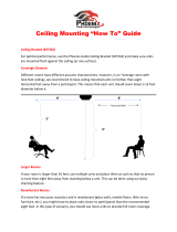
Figure 2-1. Robinson and Dadson Equal Loudness Curves
The equal loudness curves are used when sound levels are measured with a sound level meter.
If the meter has a “flat” response, then the displayed result shows a larger than perceived level
when sounds with significant low frequencies are measured. For this reason, sound level meters
have a correction or “weighting” filter built-in. This filter can more closely match the displayed
reading with the ear’s response. The most widely used weighting curve (and the one required by
NFPA 72) is the “A” weighted curve, which is approximately the inverse of the 40 phon equal
loudness curve. Meters configured with the “A” weighted filter read out in units of dBA, short for
“A” weighted decibels.
Other common weighting curves are the “B” and “C” curves, which approximate the ear’s
response at higher decibel levels. From a practical standpoint these curves are useful for
estimating the frequency content of the background noise during a room survey, but cannot be
used to validate the audibility of an emergency voice/alarm communications signal.
Note: The ear is capable of perceiving a difference in the sound level only when the sound level
has roughly doubled or halved. The dBA scale is a logarithmic scale, so a doubling of
sound power represents a 3 dBA increase in the SPL of the sound. Therefore, most
listeners can not perceive changes in SPL of less than 3 dBA. For a sound to be
perceived as twice as loud, the power must be increased 10 fold.
Sound and Hearing
The Relationship
Between Sound
and Hearing
The non-linear nature of the ear’s
response to frequencies and
loudness is well documented in
the Fletcher-Munson equal
loudness curves, updated in the
Robinson and Dadson equal
loudness curves that were adopted
in the ISO (International Standards
Organization) Recommendation
R-226.
Note: The MAF Curve in Figure 2-1
represents the “Minimum
Audible Field” Curve.

2-5
The frequency of speech ranges over seven octaves from 125 Hz to 8,000 Hz, with the majority of
frequencies contributing to intelligibility falling between 500 Hz and 4,000 Hz. The creation of
“phonemes,” or the sounds that make up words is created by amplitude modulation of those
frequencies. Amplitude modulations of speech patterns are seen as the peaks and valleys of the
waveform. These modulations range from 0.63 Hz to 12.5 Hz. A typical fragment of speech:
“an emergency has been reported” is shown in the figure below.
Figure 2-2. Speech Pattern that Illustrates Modulations
Consonants generally have the lowest power contribution to speech, but are extremely important
to intelligibility. Consonants like the “T” and “S” sounds are relatively high in frequency, but of a
short duration. Vowels (A, E, I, O, U sounds) carry most of the power of the speech signal.
The Nature of Speech
Introduction
Consonants
and Vowels

2-6
This section is provided as a summary of room acoustics. See the references in the “Related
Documentation” section earlier in this manual for a list of publications containing more thorough
discussions of this subject.
The concept of reverberation is one of the most important contributions to intelligibility
degradation. Reverberation is produced when sound is reflected off walls and other surfaces.
What the listener hears is the direct sound from the speaker plus the reflected sound from the
reverberation. Reverberation should not be confused with echoes. An echo is a delayed but
distinct reproduction of an original sound, where reverberation contains the original sound
jumbled into something not distinctly identifiable as part of the original signal.
Note: In the distributed speaker system typical of fire alarm applications, echoes are generally
not a problem, but reverberation can have a major impact on intelligibility.
Reverberation Time (also known as T60 times) is the amount of time it takes for a sound to
diminish to 60 dB below the original level. For example, to estimate a room’s reverberation time,
pop a balloon in a room and time how long it takes for the sound to diminish.
The reverberation in a room is dependent on its dimension, construction, materials, and objects
within the room, including the room’s occupants. People and furnishings are good sound
absorbers. Reverberation levels in occupied and/or furnished rooms can be significantly lower
than levels in unoccupied/unfurnished rooms.
Each surface in a room absorbs or reflects a certain percentage of sound, characterized by the
“Absorption Coefficient” of the material. The absorption coefficient is the ratio of absorbed to
reflected sound, and has a range of 0 to 1. A hard surface, such as glass or marble has a low
absorption coefficient. This indicates that most of the energy is reflected back into the room.
Soft surfaces, such as thick carpeting and acoustic ceiling tiles, have high absorption coefficients.
Frequency content of reverberation depends on the surfaces as well. Very hard surfaces such as
tile reflect most of the frequencies, while soft surfaces like drapes absorb most frequencies. Most
surfaces fall in between, where higher frequencies are absorbed readily and lower frequencies are
either passed through or reflected.
Reverberation is also affected by the room dimensions. In general, the larger the room, the higher
the reverberation times. More precisely, reverberation is dependent on the distance between
opposing surfaces. Two rooms with the same volume (L x W x H) and the same surface materials
can have dramatically different reverberation times.
Continued on next page
Room Acoustics
Introduction
Reverberation

2-7
Several equations are available for estimating the amount of reverberation that can be expected in
a room. The equations take into account the room dimensions and surface materials to provide a
reasonably accurate estimation of a rectangular room’s reverberation time. The formulas below
are commonly used Sabine and Eyring equations:
The Sabine Equation, used when α < 0.2:
α
=
S
V049.0
T
English Units (ft)
α
=
S
V16.0
T
Metric Units (m)
The Eyring Equation, used when α > 0.2:
)]1([ln)S(
V049.0
T
α−−
=
English Units (ft)
)]1([ln)S(
V16.0
T
α−−
=
Metric Units (m)
Where:
V = Room Volume (L x W X H)
S = Total Surface Area (2LH +2LW + 2WH)
α = Average absorption coefficient, equal to the area of each surface multiplied by the
absorption coefficient for that surface, divided by the total surface area of the room
Equation 2-7. Sabine and Eyring Formulas for Calculating Reverberation Times
• Acoustical treatment:
Adding drapes, wall hangings, carpeting, or specially designed diffusers can absorb sound and
reduce reverberation. If possible, this is perhaps the best method in combating reverberation.
Note: Final room acoustics are often unknown at the time of the system design.
• Speaker Placement:
Because reverberation is caused by reflections, it is important to select speaker locations that
minimize stray energy. Sound system designers are often heard saying “put the sound where
people are and do not put sound where people are not.” This usually implies locating
speakers toward the center of the room, away from walls and other hard surfaces. When
possible, aim speakers towards soft surfaces such as rugs or upholstered furnishings.
These soft surfaces absorb direct sound coming from the speaker, preventing the sound from
scattering throughout the room.
Continued on next page
Room Acoustics, Continued
Estimating
Reverberation Times
Countering the
Effects of
Reverberation

2-8
• Increasing the Signal-to-Noise Ratio:
Intelligibility degradation from reverberation is essentially a signal-to-noise issue, however
when the noise is specifically caused by reverberation it is referred to as the “Direct-to-
Reverberant” ratio. Increasing the direct sound field at the listener improves the direct to
reverberant ratio and therefore the signal-to-noise ratio. You can increase the direct sound in
several ways:
1. Move the speaker closer to the listener and reduce the wattage of the speaker:
This places the sound where it is needed and minimizes excitation of the room’s
reverberation, at the expense of additional speakers.
2. Increase the speaker density and reduce the wattage to each speaker:
This increases the direct sound heard by the listener by creating overlapping regions
of coverage.
3. In areas with high ceilings, specify a more directional speaker:
A speaker that is more focused (has a higher “Q”) concentrates most of the sound energy
in a tighter beam than low “Q” devices. This is important in areas with high ceilings to
reduce the effect of multiple late arriving sounds.
Note: See the section later in this chapter entitled “Speaker Dispersion Angle and ‘Q’”
for more information.
Room Acoustics, Continued
Countering the
Effects of
Reverberation,
(continued)

2-9
Speakers are essentially “point sources” of sound. Sound radiates outward in all directions,
creating a spherical sound pattern. The sound pressure is spread over an increasingly larger
surface area as the sound moves away from the source. This causes a drop in loudness per unit
area. The drop in SPL is referred to as the “Inverse Square Law,” and originates from the fact that
as the diameter of the sound-sphere doubles, the surface area increases by a factor of four. This
behavior of outwardly radiating sound causes a drop in SPL of –6 dB per doubling of distance.
You can calculate the change in SPL at any distance from a speaker as follows:
D1 D2
∆ dB
spl
= 20 log
2
1
D
D
Equation 2-8. The Inverse Square Law
The figure below illustrates how SPL decreases with distance as you move away from a speaker:
Figure 2-3. dB and Distance Chart
Continued on next page
Speaker Basics
Inverse Square Law

2-10
The amount of sound that a speaker can be expected to produce is found in the speaker’s
sensitivity rating provided in the manufacturer’s literature. “Sensitivity” is the amount of sound
(SPL) produced by the speaker with a known signal frequency, power level and distance from the
speaker. For fire alarm listed speakers approved under UL Standard 1480, the sensitivity is rated
at 1 W of power and 10 feet (3 meters) from the speaker. By knowing the speaker’s sensitivity,
you can determine the on-axis SPL (SPL measurements taken directly in-line with the speaker) at
any distance from the speaker using the following equation:
SPL = Sensitivity + 20 log
D
Dr
Equation 2-9. On-Axis SPL Calculation
Simplex speakers have two sensitivity ratings listed on their respective data sheets, a reverberant
chamber test as required by UL Standard 1480 and an anechoic rating as defined by ULC-S541.
The reverberant chamber specification is derived from a test where the speaker’s sound is emitted
in a chamber specifically designed to reflect all of the sound so that a total sound power
measurement can be made. Correlating the speaker’s reverberant chamber sensitivity rating with
real-world acoustics has proven to be difficult. Typically, the anechoic rating at 1 kHz is more
representative of real world performance.
The speaker sensitivity rating, while useful for comparing speaker models, tends to oversimplify
the true response of a speaker. Speakers “beam” sounds analogous to the way a flashlight
produces light: the beam of sound is loudest directly in-line with the device and becomes quieter
the farther the listener moves away from the center. This beaming effect is also dependent on the
frequency of the signal.
The beaming effect is referred to as the directivity or “polar response” of the speaker, and is
occasionally provided by manufacturers in the form of “polar plots.” For typical fire alarm
speakers the beam is very wide for low frequencies (low directivity) and becomes more focused
for higher frequencies. When determining coverage area, it is common practice to use the
directivity information at 2 kHz: a critical band for intelligibility. Fire alarm speakers produce the
highest output in the 800 to 4 kHz frequency range.
Continued on next page
Speaker Basics, Continued
Sensitivity
Speaker Dispersion
Angle and “Q”
Where:
• SPL = Sound Pressure Level
• D = Distance from the speaker
• Dr = The reference distance
• Sensitivity = The SPL at the
reference distance.
/