Page is loading ...

Head Cap Bolt
11 pcs. (+1extra)
Hex Wrench
1 pc.
Pull Handle
4 pcs.
Machine Screw
for Pull Handle
8 pcs.
Wood Screw
for Caster
16 pcs. (+2 extra)
Adjustable Pin
12 pcs. (+2extra)
Head Cap Bolt (short)
for Side Towel Bar
2 pcs. (+1 extra)
Head Cap Bolt
(short) for Top
4 pcs. (+1 extra)
Wood Plug
8 pcs.
(+2 extra)
Caster
two lock
two non-lock
4 pcs.
Steel Plate
Connector
for Top
4 pcs.
Flat
Washer
for Top
4 pcs. (+1 extra)
Spring
Washer
for Top
4 pcs. (+1 extra)
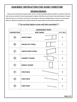
88 9200 001C
Kitchen Cart
PART LIST
B.
Side Panel
1 pc.
C.
Middle Panel
2 pcs.
E.
Back Panel
2 pcs.
F.
Back Panel
1 pc.
G.
Back Piece
2 pcs.
H.
Back Stretcher
1 pc.
I.
Front
Stretcher
1 pc.
J.
Base
1 pc.
K.
Door
.2 pcs
L.
Door
2 pcs.
(For Drawer N, packed in separate carton
with hardware and assembly instructions.)
P.
Adj. Shelf
2 pcs.
Q.
Adj. Shelf
1 pc.
HARDWARE LIST
D.
Side Panel
1 pc.
M.
Drawer
Divider
1 pc.
N.
KD. Drawer
2 pcs.
O.
Towel Bar
1 pc.
R.
Side Rack
1 pc.
S.
Side Rack
1 pc.
T.
Base Rack
1 pc.
IMPORTANT NOTE
Carefully remove all the parts from the carton and put
them individually on a soft cloth to prevent scratches
or other damages occuring to the parts.
We have taken great care in the design of this
product and request that you carefully and strictly
follow our assembly instructions to ensure a
completed product as it was designed.
Tools required for assembly : Phillips screwdriver
Home Styles Consumer Assistance Line 888-680-7460 and 877-831-0319
Small
Hex Wrench
1 pc.
Revised date : 30Oct2012
U.
Brush Chrome Pipes
3 pcs.

Assembly Instructions 2/3
STEP 1
STEP 2
STEP 3
Tighten Head
Cap Bolt by
Hex Wrench.
B
D
H
E
E
M
F
O
I
J
G
C
C
G
D
Attach four Casters to the Base (J) with
Wood Screws.
(See the ‘Arrow’ sticker indicating front area
on the base.)
Slide the Back Panel (E) and (F) in places.
Attach the Back Stretcher (H) and Front
Stretcher (I) to the unit with Head Cap Bolts
through the Side Panel (D).
Tighten Head Cap Bolts half way.
Attach the Drawer Divider (M) in between
the Back Stretcher (H) and Front Stretcher
(I), using Head Cap Bolt.
Attach the Side Panel (B) to the unit, using
Head Cap Bolts.
Tighten up all Head Cap Bolts.
Attach the Towel Bar (O) to the Side Panel (D), using Head Cap Bolts (short).
Attach the Side Panel (D) to the Base (J).
Tighten Head Cap Bolt only half way.
Attach the Back Piece (G) to the Base
and the Middle Panel (C) to the Back Piece (G).
IMPORTANT
Do not tighten up all the screws until each part is properly assembled.
You should keep Hex Wrench in the safe place as you may need to
tighten up the Head Cap Bolts in the future.
Head Cap Bolt
Locking Casters
Head Cap Bolt
(short)
Head Cap Bolt
Head Cap Bolt

STEP 5
STEP 4
STEP 6
(Figure 1)
(Figure 2)
Put the Adjustable Pins into the side panels
at the desired level. Place Shelf (P),(Q).
Slide the Drawer (N) into places.
Assembly Instructions 3/3
K
K
L
L
P
P
Q
N
N
STEP 7
Cover up all holes with
Wood Plugs
Install the Doors (K) and (L), using
Spring Pin Hinge.
(See figure 1)
Assemble the Door Pull Handles,
using the Machine Screws.
(See Figure 2)
T
R
B
S
Attach the Side Rack (R) to the Side Panel (B)
with the Head Cap Bolt.
Attach the Brush Chrome Pipes (U) to the pre-drilled
holes of Side Rack (R).
Attach the Base Rack (T) to the Side Rack (R).
Attach the Side Rack (S) to the Side Panel (B),
using Head Cap Bolt.
Head Cap Bolt
Adjustable Pin
U
*** See the process in assembling the top in separate sheet.

Assembly
Instructions
UNIT PART LIST
N1.
Front Part
2 pcs.
N3.
Side Part
2 pcs.
N4.
Side Part
2 pcs.
N5.
Bottom
2 pcs.
N2.
Back Part
2 pcs.
N2
N2
N5
N5
N3
N4
N4
N4
N3
N3
N1
N1
N1
Figure 2
Figure 3
Figure 4
Assemble the Pull Handle
with Machine Screw on
the Front Part (N1).
Turn the assembled drawer over and slide the
Plywood Bottom Part (N5) into the grooves
on Side Parts (N3) and (N4). Be sure to push
the plywood all the way forward so it meets the
Front Part (N1).
HARDWARE LIST
Pull Handle
2 pcs.
Machine Screw
for Pull Handle
4 pcs.
Wood Screw / ”
1
2
(for Bottom Part)
12 pcs.
Wood Screw 1”
(for Side Part)
16 pcs.
Drawer (N)
N1
N2
N3
N5
N4
Figure 1
Line up Side Parts (N3) and (N4) to the Front Part
(N1) and Back Part (N2). Be sure to follow the
‘Arrow’ sign sticker on the parts.
Using a screw driver, insert 1” screwsPhillip’s
into each of the 4 pre-drilled holes on Side Parts
(N3) and (N4), then tighten half way.
Insert the remaining (6) 1/2” screws
into the pre-drilled holes on Bottom Part
(N5), then tighten all screws
MAKE SURE ROLLER
IS ON THE BACK
* If you are missing any of these
parts, please contact our DMI
Customer Service Department
at 1-877-831-0319 or fax us at
1-800-755-2878.
Figure 1
Figure 2
Figure 3
Figure 4

Slide the Drawers into place.
Now, you’ll be able to create your own kitchen cart.
Make your own choice of the ‘Top’, wood or
stainless steel or granite.
Remove Drawers from the unit.
Place the selected ‘Top’ on the unit,
attach it to the body with
the Steel Plate Connectors,
Flat Washers, Spring Washers and
Head Cap Bolts. (See figure 1)
PART LIST
HARDWARE LIST
X.
Top Support
2 pcs.
Head Cap Bolt
6 pcs. (+1 extra)
The Top Support (part X) and Head Cap Bolts
are particular parts required for 9100 series only,
they are not necessary for 9200 series.
Attention !
This Top can be used for both kitchen cart
9100 series and 9200 series.
A
Head Cap Bolt
(short)
Steel Plate Connector
Steel Plate
Connector
Flat Washer
Spring Washer
Head Cap Bolt
(short)
(Figure 1)
9200 Top Assembly
Instructions
W.
Top
1 pcs.
STEP 1
/