Page is loading ...

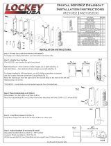
Step 5: Verify Correct Spindle Length
1. With latch (#13) installed, hold
the Inside Body (#2) and Rubber Trim
Plate (#3) to the door.
2. Place Spindle (#6/7) through latch, into
the Inside Body, as far as possible.
3. Spindle should extend from exterior of door
3/8” min. – 5/8” max.
4. If the 30-45 mm (#7) is too long, cut it to the correct length.
IMPORTANT: If spindle extends less than 3/8” it may not engage the lock. If spindle
extends more than 5/8”, it will cause the lock to bind.
Step 6: Determine Knob Turn Direction (to unlock)
The lock is preset to unlock when turned clockwise after combination is
entered.
If desired, you can unlock the door with a
counter-clockwise turn. Remove the two
blue screws and move the pin to the
opposite side as shown.
*M230 DC – Inside Body pin must on opposite side from Outside Body.
No.
Part Name
M230
1
Outside Body
1
2
Inside Body
1
3
Rubber Trim Plate
2
4
Mortised Strike
1
5
Strike Plate
1
6
Spindle 40-55 mm.
1
7
Spindle 30-45mm.
1
8
Machine Screw M4 x 50 mm.
2
9
Machine Screw M4 x 35 mm.
2
10
Wood Screw M4
4
11
Extra Code Tumblers (Red)
1
12
Extra Non-Code Tumblers (Blue)
2
13
Adjustable Latch 2 3/8” – 2 3/4”
1
14
Tweezers
1
15
Hex Bolts
2
16
Brass Support Pin
1
Door Edge
Step 7: Install the DIGITAL M230
1. Place the Rubber Trim Plate (#3) on the
backside of the Outside Body (#1).
2. Place the Outside Body
on the door. The hexagonal
bolts (#15) should extend
into the top and bottom holes.
3. The Support Pin (#16) on the Inside
Body should fit into and extend through
the hole in the Latch (#13).
INSTRUCTIONS CONTINUED ON REVERSE SIDE
Step 4: Install Support Pin & Hex Bolts
Install Brass Support Pin (#16) into Inside
Body as shown in the figure to the
Right [Left].
Install/screw Hex Bolts (#15) into the top
and bottom of the Outside Body
as shown in the figure [Far Right].
Step 3: Adjust Latch (if necessary) & Install
1. Adjustable latch (#13) is factory preset for a 2 3/8” backset.
2. For 2 3/4” backsets, slide the Cam assembly on the latch to 2 3/4”.
3. Insert latch into door and secure with Wood Screws (#10).
DIGITAL M-230 | M230 DC
Installation Instructions
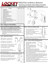
Step 2: Prep Door for Installation with Template
1. Place template (supplied) on door and fold along door’s edge.
2. Mark holes for 2 3/8” or 2 3/4” backset.
3. Drill holes as instructed.
NOTE: For Pre-Prepped 2 1/8” doors, you only need to drill top hole.
Inside Body (#2)
Spindle (#5/6)
3/8” to 5/8”
Step 1: Change User Code (OPTIONAL)
If you wish to change your code, see instructions on reverse side.
Thumb-Turn
Inside Body
Outside Body
2 3/8”
2 3/4”

Step 7 cont: Install the DIGITAL M230
1. Insert the Spindle (#6/7) into the Outside Body (#1) ensuring it’s in the proper angled position.
*(SEE FIGURES BELOW)
2. Using a screwdriver, secure the lock to the door with the Screws (#8 or #9).
Screw length is dependent on door thickness.
3. Test the operation of the Latch by turning the inside thumb-turn.
4. Locate position where Latch strikes door frame and install Mortised Strike (#4) and Strike Plate (#5).
*IMPORTANT: SPINDLE POSITION/ANGLE
CLOCKWISE TURN TO UNLOCK WITH COMBINATION
The M230 is factory preset to unlock with a clockwise turn
when the combination is entered. The Spindle MUST be placed
through the latch, at a 10:00 – 4:00 angle as shown.
COUNTER-CLOCKWISE TURN TO UNLOCK WITH COMBINATION
If desired, the M230 can be unlocked with a counter-clockwise
turn when the combination is entered. To unlock the M230 with a
counter-clockwise turn, please refer to Step 6 to change the
Handing Pin.
After changing the Handing Pin, the Spindle MUST be placed
through the latch at a 2:00 – 8:00 angle as shown.
6. Replace the cover plate and secure with two (2) Red Screws,
using a #2 screwdriver.
7. TEST CODE before installing/re-installing lock.
4. With the thumb-turn held to right or left, remove/add CODE (Red) and
NON-CODE (Blue) Tumblers to create your desired code.
Ex: 3 Red = 3-Digit Code / 6 Red = 6-Digit Code
IMPORTANT: Ensure notched side of tumbler fits into slot. (Below – Far Right).
5. After changing your code, release the thumb-turn to secure the tumblers
in place.
3. TURN & HOLD thumb-turn to right or left to release tumblers.
IMPORTANT: THUMB-TURN MUST be turned and held when removing
and inserting tumblers. Failure to do so will damage the lock and void
the warranty.
DIGITAL M-Series
How to Change Code
1. Using a #2 screwdriver, remove the two (2) Red Screws.
2. Carefully remove cover plate.
WARNING: Springs are attached to plate.
RED = CODE TUMBLERS
BLUE = NON-CODE TUMBLERS
WARNING:
Do NOT force tumblers into position!
TURNING THUMB-TURN =
CLEAR POSITION

60 mm 60 mm
MEASURE CENTER FOR
22mm HOLE FOR LATCH
OR ADJUST AS NECESSARY
TEMPLATE
LOCKEY M230
MEASURE CENTER FOR
22mm HOLE FOR LATCH
OR ADJUST AS NECESSARY
/