Comtrol ES8108 Series Installation guide
- Category
- Network switches
- Type
- Installation guide

QUICK INSTALLATION GUIDE
2000578 Rev B | Release Date - August 2014
ROCKETLINX
ES8108
ES8108/ES8108F/ES8108-XT/ES8108F-XT

INTRODUCTION
The RocketLinx ES8108 series of industrial Ethernet switches include the
following models:
• ES8108 with eight 10/100BASE-TX ports
• ES8108F with six 10/100BASE-TX and two 100BASE-FX (Single-Mode or
Mul-Mode ber) ports
• ES8108-XT with eight 10/100BASE-TX ports and an extended
temperature range
• ES8108F-XT with six 10/100BASE-TX, two 100BASE-FX (Single-Mode or
Mul-Mode ber) ports and an extended temperature range
The dierent ES8108 models are simply referred to as the ES8108 unless there
is model-specic informaon.
Refer to the Comtrol web site for specicaon informaon.
ES8108-XT/ES8108F-XT IN CID2 ENVIRONMENTS
The ES8108-XT and ES8108F-XT are open-type and are to be installed in an
enclosure suitable for the environment and only accessible with a tool.
The ES8108-XT/ES8108F-XT is suitable for use in Class I, Division 2, Groups A,
B, C, and D or non-hazardous locaons only.
WARNING - EXPLOSION HAZARD – Substuon of any components in the
ES8108-XT or ES8108F-XT may impair suitability for Class I, Division 2.
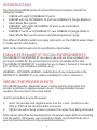
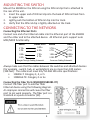
WIRING THE POWER INPUTS
The ES8108 provides redundant power, reverse polarity protecon and
accepts a posive or negave power source. If using redundant power
supplies, they must be in the same mode.
Use this procedure to wire the power:
1. Insert the posive and negave wires into the + and - contacts on the
PW1 or PW2 on the terminal block connector.
2. Tighten the wire-clamp screws to prevent the wires from being loosened.
Note: Power should be disconnected from the power supply before connecng
it to the switch. Otherwise, your screwdriver blade can inadvertently short
your terminal connecons to the grounded enclosure.
1

Power Supply
AC Power Input
10-60VDC
(UL Listed)
V-
V+
Verify the Power Input requirements
on the product label.
Power Supply
AC Power Input
12-24AWG
12-24AWG
V-
V+
DC Power Input
10-60VDC
10-60VDC
DC Power Output
10-60VDC
(UL Listed)
Dry Relay
Output
PWR1PWR2
-
+
-
+
WARNING - EXPLOSION HAZARD – Do not disconnect the ES8108-XT or
ES8108F-XT unless the power has been removed or the area is known to be
non-hazardous.
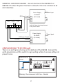
GROUNDING THE ES8108
There is an earth ground screw on the boom of the ES8108. Connect the
earth ground screw of the switch to a grounding surface to ensure safety and
prevent noise.
2
PW1
Alm
PW2
Alarm Control
port 1~8 power
Earth Ground
Screw
Earth Ground
Warning: Do not connect to AC line – Neutral

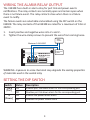
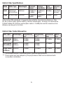
WIRING THE ALARM RELAY OUTPUT
The ES8108 has a built-in alarm-relay for port link and power events
nocaons. The relay contacts are normally open and remain open when
there is no failure event. The relay contacts close when there is a failure
event to nofy.
The failure events are selectable and enabled using the DIP switch on the
ES8108. The relay contacts of the ES8108 are rated for a maximum of 0.5A at
24VDC.
1. Insert posive and negave wires into V+ and V-.
2. Tighten the wire-clamp screws to prevent the wires from coming loose.
WARNING - Exposure to some chemicals may degrade the sealing properes
of materials used in the sealed relay
SETTING THE DIP SWITCH
Switch Status Descripon
1 to 8
(Port)
ON Enables port link down alarm for the corresponding port
OFF Disables port link down alarm for the corresponding port
9
(Power)
ON Enables the power failure alarm
OFF Disables the power failure alarm
3
Maximum 0.5A/24VDC
PW1
Alm
PW2
Alarm Control
port 1~8 power
Alarm
System
Extra Power
System

4
MOUNTING THE SWITCH
Mount the ES8108 on the DIN rail using the DIN rail clip that is aached to
the rear of the unit.
1. Insert the upper end of DIN rail clip into the back of DIN rail track from
its upper side.
2. Lightly push the boom of DIN rail clip into the track.
3. Verify that the DIN rail clip is ghtly aached on the track.
CONNECTING TO THE NETWORK
Connecng the Ethernet Ports
Connect one end of an Ethernet cable into the Ethernet port of the ES8108
and the other end to the aached device. All Ethernet ports support auto
MDI/MDIX funconality.
Always make sure that the cables between the switches and aached devices
(for example - switch, hub, or workstaon) are no more than 100 meters
(328 feet). The cable must meet EIA/TIA-568 100-ohm specicaons:
• 10BASE-T: Category 3, 4, or 5
• 100BASE-TX: Category 5 or 5e
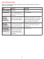
Connecng the Fiber Ports (ES8108F/ES8108F-XT)
Connect the ber port to another ber
Ethernet device using the following diagram.
An improper connecon will cause the ber
port to not work properly. The ber port is a
standard or square connector (SC).
3 TD+
6 TD-
3 RD+
6 RD-
Switch Router or PC
1 RD+
2 RD-
1 TD+
2 TD-
Straight-Through Cabling Schematic
3 TD+
6 TD-
3 TD+
6 TD-
Switch Switch
1 RD+
2 RD-
1 RD+
2 RD-
Crossover Cabling Schematic

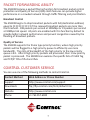
Opcal Fiber Specicaons
Mode Cable Type Wavelength Transmit
Power
Receive
Sensivity
Link
Budget
Distance
(km)
Mul 50/125um
62.5/125um
1310nm -20dBm to
-14dBm
-31dBm to
0dBm
11dBm 2km Note
(below)
Single 8-10/125um 1310nm -15dBm to
-8dBm
-34dBm to
8dBm
19dBm 30km
Note: In the IEEE standards, it suggests the available transmission distance is 2km
for 62.5/125um ber opcal cable in 1310nm wavelength. Actually, the aenuaon
of Mul-Mode 62.5/125um opcal ber cable is 1.5dBm/km and the maximum link
distance can be up to 4 to 5km.
Opcal Fiber Cable Aenuaon
Fiber Type Wavelength Aenuaon/
km*
Aenuaon/
km**
Connector
Loss
Splice
loss
Mul-Mode
50/125um
850nm
1310nm
3.5dBm
1.5dBm
2.5dBm
0.8dBm
0.75dBm 0.1dBm
Mul-Mode
62.5/125um
850nm
1310nm
3.5dBm
1.5dBm
3.0dBm
0.7dBm
0.75dBm 0.1dBm
Single-Mode
9/125um
1310nm 0.4dBm 0.35dBm 0.75dBm 0.1dBm
* These values are per TIA/EIA and other industrial specicaons
** These values are one example of the performance that can be obtained with
a new ber installaon.
5

LED INDICATORS
There are system diagnosc and Ethernet port LEDs located on the front
panel of the ES8108.
LED LED Lit LED O
PWR 1/ PWR 2
Powered No Power
Alm (Alarm)
Port Link is down or a
power failure event has
occured.
Not acvated
Port 1-8
(ES8108/
ES8108-XT)
A green lit LED indicates
that a network device is
detected and linked up.
If the green Link LED is lit and the
yellow speed LED is o, a network
device is detected and a link has
been established at 10Mbps.
Port 1-6
(ES8108F/
ES8108F-XT)
A yellow lit LED indicates
that a network device is
detected and linked up.
Both green and yellow LEDs are
not lit - a port link has not been
established.
Fiber Ports
7-8 (ES8108F/
ES8108F-XT)
A green lit LED indicates
that a network device
is detected and a link
has been established at
100Mbps.
No acve link
6

PACKET FORWARDING ABILITY
The ES8108 features a packet ltering funcon for broadcast packet control
protecon and Quality of Service (QoS). Both features can provide higher
performance in a crowded network through trac ltering and priorizaon.
Broadcast Control
The ES8108 begins to drop broadcast packets with DA (desnaon address)
equal to FF:FF:FF:FF:FF:FF if the received broadcast packets are more than
the threshold - 198 packets per second at 100Mbps or 19 packets per second
at 10Mbps link speed. All ports are enabled with this funcon by default to
provide beer network performance and prevent congeson caused by the
ooding of broadcast packets.
Quality of Service
The ES8108 supports the frame type priority funcon, where high priority
packets will be agged to a high priority queue to eciently use more
bandwidth. The rao of bandwidth of the high priority to the low priority
queue is 8:1. Aer 8 high priority packets are processed, then 1 low priority
packet is processed. The ES8108 can examine the specic bits of VLAN Tag
and TCP/IP TOS of IPv4 and IPv6.
COMTROL CUSTOMER SERVICE
You can use one of the following methods to contact Comtrol.
Contact Method Web Address or Phone Number
Support hp://www.comtrol.com/support
Downloads p://p.comtrol.com/html/default.htm
Website hp://www.comtrol.com
Phone +1 763.957.6000
7
-
 1
1
-
 2
2
-
 3
3
-
 4
4
-
 5
5
-
 6
6
-
 7
7
-
 8
8


Comtrol ES8108 Series Installation guide
- Category
- Network switches
- Type
- Installation guide
Ask a question and I''ll find the answer in the document
Finding information in a document is now easier with AI
Related papers
-
Comtrol MC7001 Installation guide
-
-
-
-
-
-
-
-
-
Other documents
-
Repotec RP-ISF500 Owner's manual
-
Intellinet 470063 Datasheet
-
LevelOne IFS-0501 Installation guide
-
LevelOne IFS-0503 Installation guide
-
KTI Networks 100Base-FX Fast Ethernet PCI Adapter KF-221FX Ver.C User manual
-
LevelOne IFS-0502 Installation guide
-
-
-
CTC Union IFC-CCF40 Quick Installation Manual
-
CTS WAS-3005 User guide