Page is loading ...

www.comtrol.com
2000561 Rev A
Comtrol Customer Service
You can use one of the following methods to contact Comtrol Corporation.
4
5
All the Fast Ethernet ports automatically detect the signal from the connected devices
to negotiate the link speed and duplex mode. Auto MDI/MDIX allows you to connect
another switch, hub, or workstation without changing straight-through or crossover
cables. Crossover cables cross-connect the transmit lines at each end to the received
lines at the opposite end.
The Ethernet cables use Pins 1, 2, 3, and 6 of an 8-pin RJ45 connector. The signals of
these pins are converted by the automatic MDIX function, as shown in the following
table:
Connect one side of an Ethernet cable into any switch port and connect the other side
to your attached device. The wiring cable types and maximum cable length are as
follows.
Uplink ports: 10BASE-T: 2-pair UTP/STP Category 3, 4, 5 cable, EIA/TIA-568
100-ohm (100 meters)
Uplink ports: 100BASE-TX: 2-pair UTP/STP Category 5 cable, EIA/TIA-568
100-ohm (100 meters)
Uplink ports: 1000BASE-TX: 4-pair UTP/STP Category 5 cable, EIA/TIA-568
100-ohm (100 meters)
PoE ports: 4-pair UTP/STP Category 5e / 6 cable, EIA/TIA-568 100-ohm
(100 meters)
3 TD+
6 TD-
3 RD+
6 RD-
Switch Router or PC
1 RD+
2 RD-
1 TD+
2 TD-
Straight-Through Cabling Schematic
3 TD+
6 TD-
3 TD+
6 TD-
Switch Switch
1 RD+
2 RD-
1 RD+
2 RD-
Crossover Cabling Schematic
Pin MDIX Signals MDI Signals
1 RD+ TD+
2 RD- TD-
3 TD+ RD+
6 TD- RD-
Quick Installation Guide
Contact Method Web Address or Phone Number
Support http://www.comtrol.com/pub/en/support
Downloads
Web Site http://www.comtrol.com
Phone 763.957.6000
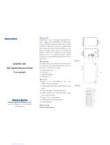
ROCKETLINX ES7106-VB
Industrial PoE Switch
ftp://ftp.comtrol.com/html/ES7106_VB.htm

Port G2 Port G1 Port 1 Port 2 Port 3 Port 4 Port 5 Port 6 Port 7 Port 8
DIP 1 DIP 2 DIP 3 DIP 4 DIP 5 DIP 6 DIP 7 DIP 8 DIP 9 DIP 10
Maximum 1A/24VDC
Alarm System
Extra Power
System
Port Alarm
Earth Ground
Overview
The RocketLinx ES7106-VB is an industrial Power over Ethernet (PoE) switch with
four Fast Ethernet PoE ports and two Gigabit uplink ports to ensure a high-bandwidth
connection. The ES7106-VB is compliant with the IEEE 802.3af PoE standard to
deliver a maximum of 15.4W per port.
To ensure high quality video data transmission, the ES7106-VB not only
provides Gigabit bandwidth uplink for large image traffic, but also
supports QoS to adjust the priority of data transfer. Using the Fault
Relay, the ES7106-VB can automatically warn the administrator if there
are any failures. The compact IP30 rigid aluminum case allows the
ES7106-VB to be reliably operated in an extreme environment (-25° to 60°C).
Refer to the Comtrol web site for detailed specifications.
Set the DIP Switch
The ES7106-VB has a 6-pin DIP switch located on the bottom panel to configure the Port
Link Alarm for the Ethernet ports. The following table shows the DIP switch number mapping
to the corresponding PoE and Gigabit ports as follows:
1
2
3
Wire the Power
Use the following procedure to wire the power and ground.
1. Disconnect the terminal block
from the ES7106-VB.
2. Insert the positive and negative
wires (12-24AWG) into the
PWR+ and PWR- contacts.
Note: Make sure that the power
supply is OFF before connecting
it to the switch. Otherwise, your
screwdriver blade can
inadvertently short your terminal connections to the grounded enclosure.
3. Tighten the wire-clamp screws to prevent the wires from coming loose.
4. Plug the terminal block into the ES7106-VB.
Wire the Relay Output and Ground
The ES7106-VB provides Relay Output. The relay contacts are energized (open) for
normal operation and will close under a faulty condition, such as, an Ethernet port link
break. The Relay alarm can be configured by the DIP switches.
1. Insert positive and negative
wires into Relay A and Relay B.
2. Tighten the wire-clamp screws
to prevent the wires from
coming loose.
3. Connect a ground wire
between the chassis and earth
ground using 12-24AWG wire
to ensure that the ES7106-VB is
not damaged by noise or
electrical shock.
a. Loosen the earth ground screw on the bottom of the RocketLinx ES7106-VB with
a screw driver.
b. Tighten the screw after the earth ground wire is connected.
DIN Rail Mount
The DIN rail clip is already attached on the rear side of the ES7106-VB.
1. Insert the upper end of the DIN rail clip into the back of the DIN rail track from its
upper side.
2. Lightly push the bottom of the DIN rail clip into the track.
3. Verify that the DIN rail clip is tightly attached to the track.
Connect the Ethernet or PoE Ports
You can use the following information to connect Ethernet cables between the
ES7106-VB ports and the network nodes.
Ports G1 and G2 are Gigabit Ethernet ports that support 10BASE-T,
100BASE-TX, and 1000BASE-TX.
Ports 3-6 are Fast Ethernet 10/100BASE-TX PoE ports that are IEEE 802.3af
(PoE) compliant. The Fast Ethernet ports support 10BASE-T and 100BASE-TX,
full- or half-duplex modes. The ports are labeled 1-4 on the ES7106-VB.
The following table shows the RJ45 pin-out assignments for the PoE and Gigabit ports:
DIP Switch Number
Status
Description
1-2
On
Enables the Gigabit port failure alarm for this port.
Off
(Default)
Disables the Gigabit port failure alarm for this port.
3-10
On
Enables the PoE port failure alarm for this port.
Off
(Default)
Disables the PoE port failure alarm for this port.
Relay
PWR
Relay
PWR
DC Power output
Power Supply
AC Power input
12 to 24AWG
Wire
Power Supply Requirements
ES7106-VB 12-24VDC/95W (Min)
RJ45 Pin
Number
10/100BASE-TX PoE
Signal
1000BASE-TX
Signal
1 RX +- BI_DA+
2 RX - BI_DA-
3 TX + BI_DB+
4 Vport+ BI_DC+
5 Vport+ BI_DC-
6 TX - BI_DB-
7 Vport- BI_DD+
8 Vport- BI_DD-
3-6

www.comtrol.com
2000561 Rev A
Comtrol Customer Service
You can use one of the following methods to contact Comtrol Corporation.
4
5
All the Fast Ethernet ports automatically detect the signal from the connected devices
to negotiate the link speed and duplex mode. Auto MDI/MDIX allows you to connect
another switch, hub, or workstation without changing straight-through or crossover
cables. Crossover cables cross-connect the transmit lines at each end to the received
lines at the opposite end.
The Ethernet cables use Pins 1, 2, 3, and 6 of an 8-pin RJ45 connector. The signals of
these pins are converted by the automatic MDIX function, as shown in the following
table:
Connect one side of an Ethernet cable into any switch port and connect the other side
to your attached device. The wiring cable types and maximum cable length are as
follows.
Uplink ports: 10BASE-T: 2-pair UTP/STP Category 3, 4, 5 cable, EIA/TIA-568
100-ohm (100 meters)
Uplink ports: 100BASE-TX: 2-pair UTP/STP Category 5 cable, EIA/TIA-568
100-ohm (100 meters)
Uplink ports: 1000BASE-TX: 4-pair UTP/STP Category 5 cable, EIA/TIA-568
100-ohm (100 meters)
PoE ports: 4-pair UTP/STP Category 5e / 6 cable, EIA/TIA-568 100-ohm
(100 meters)
3 TD+
6 TD-
3 RD+
6 RD-
Switch Router or PC
1 RD+
2 RD-
1 TD+
2 TD-
Straight-Through Cabling Schematic
3 TD+
6 TD-
3 TD+
6 TD-
Switch Switch
1 RD+
2 RD-
1 RD+
2 RD-
Crossover Cabling Schematic
Pin MDIX Signals MDI Signals
1 RD+ TD+
2 RD- TD-
3 TD+ RD+
6 TD- RD-
Quick Installation Guide
Contact Method Web Address or Phone Number
Support http://www.comtrol.com/pub/en/support
Downloads
Web Site http://www.comtrol.com
Phone 763.957.6000
ROCKETLINX ES7106-VB
Industrial PoE Switch
ftp://ftp.comtrol.com/html/ES7106_VB.htm
/