


Introduction
III
INTRODUCTION
Syscon 6.5 is the software tool that configures, maintains, and operates the newest SMAR products
line and communicates with the comprehensive new series of controllers. These controllers are all
connected to the High-Speed Ethernet providing field network connections to well-known protocols
such as FOUNDATION Fieldbus, Profibus, DeviceNet, AS-i and Modbus.
The friendly Man-Machine Interface (MMI) provides an efficient and productive interaction with the
user, without previous knowledge of the software. A large library of preconfigured and tested
templates for devices, control strategies and graphic symbols makes system engineering as efficient
and as fast as it can be. Only a minimum of data needs to be entered when defining I/Os,
networking, and control strategies.
The plant control configuration is now managed by a unique tool, the Studio302, which integrates
all applications included in the Smar’s SYSTEM302 Enterprise Automation System and
incorporates Windows-based Users and Groups to provide a multi-user environment. Now the
Syscon project files have controlled access defined for each professional operating the plant and a
precise register of the history of modifications to guarantee the integrity of the project configuration
data.
Syscon version 6.5 also includes the new Mapping Tool, which integrates Profibus, DeviceNet,
AS-i and Modbus configurations created using the Network Configurator to the Syscon project
configuration. Mapping Tool shows the memory mapping from controllers and instruments on the
network, blocks and I/O points, and non-standard I/O connections that are available for mapping.
Refer to the Mapping Tool Tutorial on this manual for further details about the tool.
Syscon 6.5 runs on Microsoft® Windows.
This manual refers to the version 6.5 of Syscon available on SYSTEM302 version 8.
This product is protected by US patent numbers 6,095,674; 5,841,654 and other U.S. Patents
pending.
NOTE
It is recommended that you read and follow the installation p
rocedures described on the
SYSTEM302 Installation Guide included on the product package.
Further information about SYSTEM302 version 8 is also available on the Studio302 User’s
Manual, which is included on the SYSTEM302 Installation media.

SYSCON 6.5 - User’s Manual
IV

Table of Contents
V
TABLE OF CONTENTS
INTRODUCTION .......................................................................................................................................... III
SECTION 1 - GETTING STARTED ............................................................................................................ 1.1
USING SYSCON IN STAND ALONE MODE ....................................................................................................... 1.1
USING SYSCON IN MULTI-USER MODE .......................................................................................................... 1.1
SECTION 2 - SYSCON 6.5 USER INTERFACE ........................................................................................ 2.1
WORKING WITH A STRATEGY CONFIGURATION .......................................................................................... 2.1
CREATING AN AREA ............................................................................................................................................... 2.1
CREATING A HSE AREA ......................................................................................................................................... 2.1
CONVERTING A SE AREA TO A HSE AREA .......................................................................................................... 2.2
CREATING AN AREA FROM A TEMPLATE ............................................................................................................ 2.4
OPENING AN AREA ................................................................................................................................................. 2.5
SAVING AN AREA .................................................................................................................................................... 2.6
CREATING A COPY OF THE AREA ........................................................................................................................ 2.6
PRINTING THE STRATEGY CONFIGURATION ..................................................................................................... 2.6
PREFERENCES ................................................................................................................................................... 2.9
BLOCK TAB - TAG POLICY ..................................................................................................................................... 2.9
BLOCK TAB - TAG COMPOSITION ....................................................................................................................... 2.10
BLOCK TAB - COMMUNICATION .......................................................................................................................... 2.10
BLOCK TAB - EXPORT TAG .................................................................................................................................. 2.11
DEVICE AND BRIDGE TAB ................................................................................................................................... 2.12
STRATEGY TAB ..................................................................................................................................................... 2.12
PACK AND GO TAB ............................................................................................................................................... 2.13
DEVICE SUPPORT TAB ........................................................................................................................................ 2.14
ADVANCED USER TAB ......................................................................................................................................... 2.15
LOGGER TAB ......................................................................................................................................................... 2.15
SIMULATION TAB .................................................................................................................................................. 2.16
PARAMETER TAB .................................................................................................................................................. 2.16
DATABASE TAB ..................................................................................................................................................... 2.17
AUTOMATIC BLOCK TAG GENERATION ........................................................................................................ 2.17
DEFAULT BLOCK TAG .......................................................................................................................................... 2.17
BLOCK TAG BASED ON DEVICE TAG ................................................................................................................. 2.17
BLOCK TAG BASED ON STRATEGY TAG ........................................................................................................... 2.18
SECURITY ......................................................................................................................................................... 2.19
ENABLING THE SECURITY ................................................................................................................................... 2.19
USER LOGIN .......................................................................................................................................................... 2.20
USER LOGOUT ...................................................................................................................................................... 2.20
USERS MANAGEMENT ......................................................................................................................................... 2.20
USING THE XML VIEWER WINDOW ............................................................................................................... 2.22
SECTION 3 - PLANT CONFIGURATION ................................................................................................... 3.1
AREA .................................................................................................................................................................... 3.1
CHANGING THE AREA ATTRIBUTES..................................................................................................................... 3.1
PROCESS CELLS ................................................................................................................................................ 3.2
CREATING PROCESS CELLS ................................................................................................................................. 3.2
CHANGING PROCESS CELL ATTRIBUTES ........................................................................................................... 3.3
DELETING PROCESS CELLS ................................................................................................................................. 3.3
UNITS ................................................................................................................................................................... 3.3
CREATING UNITS .................................................................................................................................................... 3.3
CHANGING UNIT ATTRIBUTES .............................................................................................................................. 3.3
DELETING UNITS .................................................................................................................................................... 3.4
CONTROL MODULES ......................................................................................................................................... 3.4
CREATING CONTROL MODULES .......................................................................................................................... 3.4
CHANGING CONTROL MODULE ATTRIBUTES ..................................................................................................... 3.4
DELETING CONTROL MODULES ........................................................................................................................... 3.5
MOVING CONTROL MODULES .............................................................................................................................. 3.5
FIELDBUS NETWORKS ...................................................................................................................................... 3.5
CREATING A H1 OR HSE FIELDBUS ..................................................................................................................... 3.5

SYSCON 6.5 - User’s Manual
VI
CREATING A PROFIBUS NETWORK...................................................................................................................... 3.6
CREATING A DEVICENET NETWORK ................................................................................................................... 3.7
CREATING AN AS-I NETWORK .............................................................................................................................. 3.7
CREATING A MODBUS NETWORK ........................................................................................................................ 3.8
IMPORTING A PROFIBUS OR DEVICENET CONFIGURATION ............................................................................ 3.8
CHANGING THE H1 OR HSE FIELDBUS ATTRIBUTES ......................................................................................... 3.8
MODIFYING THE PROFIBUS, DEVICENET, AS-I OR MODBUS CONFIGURATION ............................................. 3.9
DELETING FIELDBUSES ....................................................................................................................................... 3.10
CONTROLLERS ................................................................................................................................................. 3.10
CREATING A CONTROLLER ................................................................................................................................. 3.10
CREATING THE CONTROLLER FROM A TEMPLATE ......................................................................................... 3.11
CHANGING THE CONTROLLER ATTRIBUTES .................................................................................................... 3.11
ADDING REDUNDANCY TO THE CONTROLLER ................................................................................................ 3.11
DELETING A CONTROLLER ................................................................................................................................. 3.11
BRIDGES ........................................................................................................................................................... 3.11
CREATING BRIDGES ............................................................................................................................................ 3.11
CREATING A BRIDGE FROM A TEMPLATE ......................................................................................................... 3.12
CHANGING BRIDGE ATTRIBUTES ....................................................................................................................... 3.12
DELETING BRIDGES ............................................................................................................................................. 3.13
ADDING REDUNDANCY TO THE HSE BRIDGE ................................................................................................... 3.13
CONNECTING A BRIDGE TO A FIELDBUS .......................................................................................................... 3.15
DISCONNECTING A BRIDGE FROM A FIELDBUS .............................................................................................. 3.17
BRIDGE EXCHANGE ............................................................................................................................................. 3.17
DEVICES ............................................................................................................................................................ 3.17
CREATING DEVICES ............................................................................................................................................. 3.17
CREATING A DEVICE FROM A TEMPLATE ......................................................................................................... 3.18
CHANGING THE DEVICE ATTRIBUTES ............................................................................................................... 3.19
MASTER BACKUP DEVICE ................................................................................................................................... 3.20
DELETING DEVICES ............................................................................................................................................. 3.20
ORDERING DEVICES ............................................................................................................................................ 3.20
MOVING DEVICES ................................................................................................................................................. 3.21
DEVICE EXCHANGE.............................................................................................................................................. 3.21
FUNCTION BLOCKS ......................................................................................................................................... 3.25
CREATING BLOCKS IN THE CONTROL MODULE............................................................................................... 3.25
CREATING BLOCKS IN THE DEVICE ................................................................................................................... 3.25
CHANGING BLOCK ATTRIBUTES ........................................................................................................................ 3.26
DELETING BLOCKS............................................................................................................................................... 3.26
ATTACHING BLOCKS TO THE CONTROL MODULE ........................................................................................... 3.27
DETACHING BLOCKS FROM THE CONTROL MODULE ..................................................................................... 3.27
ATTACHING BLOCKS TO THE DEVICE ............................................................................................................... 3.27
DETACHING BLOCKS FROM THE DEVICE ......................................................................................................... 3.29
MOVING BLOCKS .................................................................................................................................................. 3.29
ORDERING BLOCKS ............................................................................................................................................. 3.29
OFF LINE CHARACTERIZATION .......................................................................................................................... 3.30
ON LINE CHARACTERIZATION ............................................................................................................................ 3.31
FLEXIBLE FUNCTION BLOCKS ....................................................................................................................... 3.32
CREATING FLEXIBLE FUNCTION BLOCKS ......................................................................................................... 3.32
DEFINING PARAMETERS FOR THE FLEXIBLE FUNCTION BLOCK .................................................................. 3.32
VIEWING AND EDITING THE LOGIC FOR THE FLEXIBLE FUNCTION BLOCK ................................................. 3.34
REPLACING FLEXIBLE FUNCTION BLOCKS ....................................................................................................... 3.35
TRENDS ............................................................................................................................................................. 3.35
CREATING A TREND ............................................................................................................................................. 3.36
CHANGING THE TREND ATTRIBUTES ................................................................................................................ 3.36
DELETING THE TREND ......................................................................................................................................... 3.37
PARAMETERS ................................................................................................................................................... 3.37
EDITING PARAMETER TAGS ............................................................................................................................... 3.37
DEFINING AREA LINK PARAMETERS.................................................................................................................. 3.39
CUSTOMIZING THE PARAMETERS LIST ............................................................................................................. 3.40
ORDERING PARAMETERS ................................................................................................................................... 3.41
DELETING PARAMETERS .................................................................................................................................... 3.41
STRATEGIES ..................................................................................................................................................... 3.41
CREATING STRATEGIES ...................................................................................................................................... 3.41
SAVING STRATEGIES ........................................................................................................................................... 3.42
IMPORTING A TEMPLATE INTO THE STRATEGY WINDOW .............................................................................. 3.42
EXPORTING A TEMPLATE FROM THE STRATEGY WINDOW ........................................................................... 3.43

Table of Contents
VII
ADDING BLOCKS TO THE STRATEGY ................................................................................................................ 3.43
DRAGGING BLOCKS TO THE STRATEGY WINDOW .......................................................................................... 3.44
REMOVING BLOCKS FROM THE STRATEGY ..................................................................................................... 3.44
SELECTING OBJECTS AT THE STRATEGY WINDOW ........................................................................................ 3.45
CHANGING BLOCKS APPEARANCE .................................................................................................................... 3.45
BLOCK LINKS .................................................................................................................................................... 3.46
GRAPHICAL REPRESENTATION FOR LINKS ...................................................................................................... 3.46
CREATING A LINK ................................................................................................................................................. 3.48
FAST LINK PROCESS ........................................................................................................................................... 3.50
LINK ATTRIBUTES ................................................................................................................................................. 3.50
REMOVING LINKS ................................................................................................................................................. 3.51
RESTORING LINKS ............................................................................................................................................... 3.51
REDRAWING LINKS .............................................................................................................................................. 3.51
RECONNECTING BLOCKS ................................................................................................................................... 3.53
SECTION 4 - COMMUNICATION .............................................................................................................. 4.1
INTRODUCTION .................................................................................................................................................. 4.1
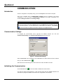
COMMUNICATION SETTINGS ........................................................................................................................... 4.1
INITIALIZING THE COMMUNICATION ............................................................................................................... 4.1
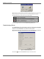
COMMISSIONING A DEVICE .............................................................................................................................. 4.2
CHECKING COMMISSIONING ........................................................................................................................... 4.4
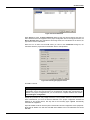
DECOMMISSIONING A DEVICE ......................................................................................................................... 4.5
ERROR LOG REGISTRY..................................................................................................................................... 4.5
DOWNLOADING THE CONFIGURATION .......................................................................................................... 4.5
INCREMENTAL DOWNLOAD .................................................................................................................................. 4.6
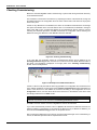
PLANT CONFIGURATION DOWNLOAD ................................................................................................................. 4.9
BRIDGE DOWNLOAD ............................................................................................................................................ 4.10
LADDER LOGIC DOWNLOAD ............................................................................................................................... 4.10
FOUNDATION FIELDBUS NETWORK CONFIGURATION DOWNLOAD.............................................................. 4.11
NON-FOUNDATION FIELDBUS NETWORK CONFIGURATION DOWNLOAD .................................................... 4.11
H1 DEVICE DOWNLOAD ....................................................................................................................................... 4.11
H1 FIELDBUS CHANNEL TRAFFIC SCHEDULE DOWNLOAD ............................................................................ 4.12
WHEN SHOULD I SAVE THE CONFIGURATION BEFORE EXECUTING THE DOWNLOAD? ...................... 4.13
USUAL CASES FOR THE DOWNLOAD PROCEDURE ................................................................................... 4.13
PLANT DOWNLOAD – NON-INCREMENTAL ........................................................................................................ 4.13
INCREMENTAL DOWNLOAD (PLANT, HSE AND H1 CHANNELS, DEVICES) .................................................... 4.13
BRIDGE, CONTROLLER OR DEVICE PARTIAL DOWNLOAD ............................................................................. 4.14
DOWNLOAD FAILURES .................................................................................................................................... 4.14
UPLOADING THE CONFIGURATION ............................................................................................................... 4.14
PARTIAL UPLOAD ................................................................................................................................................. 4.15
LIVE LIST ........................................................................................................................................................... 4.15
LIVE LIST MENU OPTIONS ................................................................................................................................... 4.16
BLOCK LIST ....................................................................................................................................................... 4.17
BLOCK LIST MENU OPTIONS ............................................................................................................................... 4.18
EXPORTING TAGS ............................................................................................................................................ 4.19
EXPORT TAGS ...................................................................................................................................................... 4.19
EXPORT TAGS FOR OPC BROWSING ................................................................................................................ 4.20
EXPORTING THE CONFIGURATION ............................................................................................................... 4.20
CONSOLIDATING THE OPC DATABASE ........................................................................................................ 4.21
ADDING A CONFIGURATION ................................................................................................................................ 4.21
REMOVING A CONFIGURATION .......................................................................................................................... 4.21
UPDATING A CONFIGURATION ........................................................................................................................... 4.21
CLEARING THE CONSOLIDATED LIST ................................................................................................................ 4.22
CHANGING THE MACROCYCLES FOR | SPECIFIC CONTROLLERS OR BRIDGES ................................... 4.23
DEFINING THE TRANSMIT DELAY TIME PARAMETER ...................................................................................... 4.23
CHANGING THE MACROCYCLE OF SPECIFIC CPUS ........................................................................................ 4.25
SECTION 5 - TEMPLATES ........................................................................................................................ 5.1
EDITING THE DEFAULT TEMPLATE ................................................................................................................. 5.1
EDITING STRATEGY TEMPLATES .................................................................................................................... 5.2
ADDING BLOCKS .................................................................................................................................................... 5.2
CHANGING THE BLOCK TAG ................................................................................................................................. 5.3
BLOCK OFF LINE CHARACTERIZATION ............................................................................................................... 5.3

SYSCON 6.5 - User’s Manual
VIII
CREATING LINKS .................................................................................................................................................... 5.3
EDITING DEVICE, BRIDGE AND CONTROLLER TEMPLATES ........................................................................ 5.3
CHANGING ATTRIBUTES ....................................................................................................................................... 5.3
CREATING BLOCKS ................................................................................................................................................ 5.4
CHANGING BLOCK ATTRIBUTES .......................................................................................................................... 5.4
BLOCK OFF LINE CHARACTERIZATION ............................................................................................................... 5.4
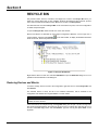
SECTION 6 - RECYCLE BIN ..................................................................................................................... 6.1
RESTORING DEVICES AND BLOCKS ............................................................................................................... 6.1
DELETING ITEMS FROM THE RECYCLE BIN .................................................................................................. 6.2
ORDERING ITEMS IN THE RECYCLE BIN ........................................................................................................ 6.2
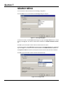
SECTION 7 - SEARCH MENU ................................................................................................................... 7.1
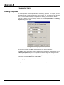
SECTION 8 - PROPERTIES ...................................................................................................................... 8.1
DRAWING PROPERTIES .................................................................................................................................... 8.1
GENERAL TAB ......................................................................................................................................................... 8.1
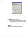
COLORS TAB ........................................................................................................................................................... 8.2
HELPER TOOLS TAB............................................................................................................................................... 8.3
BACKGROUND IMAGE TAB .................................................................................................................................... 8.4
OBJECT PROPERTIES ....................................................................................................................................... 8.5
GENERAL TAB ......................................................................................................................................................... 8.5
LINE TAB .................................................................................................................................................................. 8.6
FILL TAB ................................................................................................................................................................... 8.7
TEXT ATTRIBUTES TAB .......................................................................................................................................... 8.8
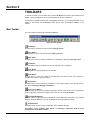
SECTION 9 - TOOLBARS ......................................................................................................................... 9.1
MAIN TOOLBAR .................................................................................................................................................. 9.1
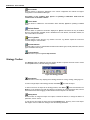
STRATEGY TOOLBAR ........................................................................................................................................ 9.2
CHARACTERIZATION TOOLBAR ....................................................................................................................... 9.4
DRAWING TOOLBAR .......................................................................................................................................... 9.6
ALIGNMENT TOOLBAR ...................................................................................................................................... 9.9
ORDERING TOOLBAR ...................................................................................................................................... 9.11
COPY ATTRIBUTES TOOLBAR ........................................................................................................................ 9.13
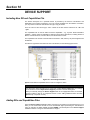
SECTION 10 - DEVICE SUPPORT .......................................................................................................... 10.1
INCLUDING NEW DD AND CAPABILITIES FILE ............................................................................................. 10.1
ADDING DDS AND CAPABILITIES FILES ........................................................................................................ 10.1
IMPORTING FILES FOR H1 DEVICES ............................................................................................................. 10.2
IMPORTING FILES FOR HSE DEVICES .......................................................................................................... 10.3
IMPORTING FILES FOR LINKING DEVICES WITH NO FBAP ........................................................................ 10.3
CHECKING MISSING DEVICE SUPPORT ....................................................................................................... 10.3
LOCATING THE MISSING FILES MANUALLY ...................................................................................................... 10.4
GENERATING THE DSM FILE ............................................................................................................................... 10.5
PACKING THE MISSING DEVICE SUPPORT FILES ............................................................................................ 10.5
IMPORTING MISSING DEVICE SUPPORT FILES ................................................................................................ 10.5
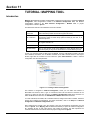
SECTION 11 - TUTORIAL: MAPPING TOOL .......................................................................................... 11.1
INTRODUCTION ................................................................................................................................................ 11.1
USER INTERFACE ............................................................................................................................................ 11.3
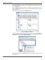
NETWORK TOPOLOGY VIEW .............................................................................................................................. 11.3
EXPANDING THE NETWORK TOPOLOGY .......................................................................................................... 11.4
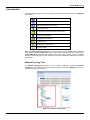
MEMORY MAP VIEW ............................................................................................................................................. 11.4
BLOCKS AND PARAMETERS VIEW ..................................................................................................................... 11.4
I/O POINT GROUP VIEW ....................................................................................................................................... 11.5
DISPLAYING THE DEVICE MODEL ...................................................................................................................... 11.5
DISPLAYING I/O POINTS TAGS ............................................................................................................................ 11.5
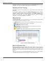
USING MAPPING TOOL .................................................................................................................................... 11.6
RENAMING BLOCKS OR I/O POINT GROUPS ..................................................................................................... 11.6
REMOVING A BLOCK OR I/O POINT GROUP ...................................................................................................... 11.6
REMOVING SEVERAL BLOCKS ........................................................................................................................... 11.6
REMOVING I/O POINTS ........................................................................................................................................ 11.7

Table of Contents
IX
MAPPING I/O CONNECTIONS .............................................................................................................................. 11.8
EDITING DIGITAL BITS .......................................................................................................................................... 11.9
EDITING I/O POINT ATTRIBUTES ...................................................................................................................... 11.10
EDITING I/O POINT ATTRIBUTES IN THE I/O POINT TABLE ............................................................................ 11.10
COPYING ATTRIBUTES IN THE I/O POINT TABLE ........................................................................................... 11.11
EDITING SCALE VALUES .................................................................................................................................... 11.12
COPYING VALUES IN THE SCALE TABLE ......................................................................................................... 11.13
SEARCHING TEXT IN THE I/O POINT OR SCALE TABLES .............................................................................. 11.13
FIND AND REPLACE A TEXT IN THE I/O POINT OR SCALE TABLES .............................................................. 11.14
DEFINING THE READING ORDER FOR BYTES ................................................................................................ 11.14
COPYING THE MEMORY MAP ........................................................................................................................... 11.15
DELETING MAPPED BITS ................................................................................................................................... 11.17
CHANGING I/O POINT OFFSET .......................................................................................................................... 11.17
SWAPPING I/O POINTS ....................................................................................................................................... 11.20
USING DEVICE TEMPLATES ......................................................................................................................... 11.23
CREATING A DEVICE TEMPLATE ...................................................................................................................... 11.23
APPLYING A DEVICE TEMPLATE ...................................................................................................................... 11.24

SYSCON 6.5 - User’s Manual
X

Section 1
1.1
GETTING STARTED
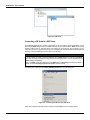
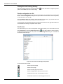
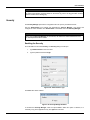
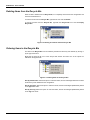
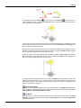
Starting on System302 version 7.0, Syscon is only executed from the Studio302 application.
From the Start menu, select Programs > System302 > Studio302 and click Studio302, as
indicated in the next figure:
Figure 1.1. Starting Studio302
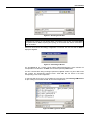
Click the button on the Studio302 toolbar to run Syscon 6.5.
Figure 1.2. Starting Syscon
Using Syscon in Stand Alone Mode
In Stand Alone mode, Syscon will save the configuration files in the local machine, and the
Database Manager will not manage the alterations made to the configurations.
Using Syscon in Multi-User Mode
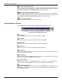
In Multi-User mode, the Database Manager manages all Syscon configuration files, which means
that any configuration file created using Syscon will be saved in a common storage folder and the
access of all machines connected to the communication network to the files will be controlled.
To guarantee that the configuration file saved in the Database Manager reflects the most recent
alterations, it is necessary to execute the Commit procedure. Open the configuration file using
Syscon and click the button Commit on the main toolbar. The Database Manager will apply
the alterations and manage the information for the other machines.

SYSCON 6.5 - User’s Manual
1.2
IMPORTANT
To update the configuration file at the machine in View Mode using the Commit procedure,
Syscon communication must be in Offline Mode.
To discard the alterations applied to a local file and restore the original configuration file from the
Database Manager, click the button Revert on the main toolbar.
To edit a configuration file managed by the Database Manager, you must have the access rights to
change that file. Also, the file must be available for edition, which means that there can’t be another
user editing the same configuration.
The button Edit/View Mode will only be available on the main toolbar when the Database
Manager is being executed and the configuration file has been already imported to the current
Studio302 Database.
When a Syscon configuration file is on View Mode, it can not be altered, because another user
may be editing that same file or because the current user does not have access rights to that file.

Section 2
2.1
SYSCON 6.5 USER INTERFACE
Working with a Strategy Configuration
A strategy configuration file (.ffp) brings together all the elements of a fieldbus network configuration.
The configuration file contains information about the plant application and the plant Fieldbus
Network.
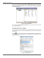
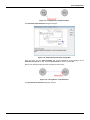
Creating an Area
To create an area, click the button New on the main toolbar and select the option Area.
The Setup New Area dialog box will open. Type the name for the area and click Ok to conclude.
The main window will open:
Figure 2.1. Strategy Configuration Main Window
Syscon will automatically create a folder with the selected configuration name inside the selected
folder. If you are using Syscon in Multi-User mode, the default path for the configuration files is
C:\Program Files\Smar\ConfigurationWorkspace\Client\CWFiles\System302.
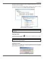
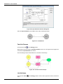
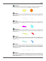
Creating a HSE Area
On the main toolbar, click New and select the option HSE Area.
In the Setup New Area dialog box, type the name for the area and click Ok to conclude. Syscon
will automatically create a HSE area adding the fieldbus channel and the Foundation Fieldbus HSE
Host.
In Multi-User mode, the default path for the configuration files is C:\Program
Files\Smar\ConfigurationWorkspace\Client\CWFiles\System302.
The main window will open as indicated in the figure below:

SYSCON 6.5 - User’s Manual
2.2
Figure 2.2. HSE Area
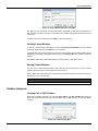
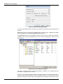
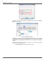
Converting a SE Area to a HSE Area
From Syscon version 6.2 on, the SE configuration can be converted to a HSE configuration, which
means that a DF51 bridge with H1 Fieldbus channels can be replaced with a DF63, and the field
devices created in the H1 channels will be connected to the channels from the new bridge. On the
other hand, blocks and parameters that are not compatible with the new bridge should be replaced
causing the least possible impact to the plant control strategy.
ATTENTION
It is not possible to directly convert the SE area using a DF51 bridge to a HSE area with DF62.
First, it is necessary to execute the steps described in this subsection to convert the SE area to a
DF63 strategy configuration.
Then, the DF63 should be replaced with the DF62 using the Exchange procedure described in
details in section Exchanging Devices at Section 3 of this manual.
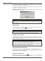
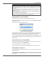
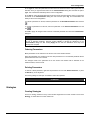
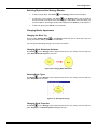
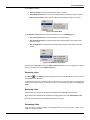
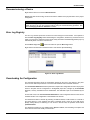
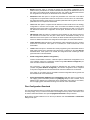
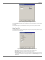
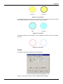
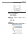
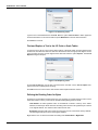
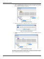
In the File menu, select the option SE to HSE Replacement to open the dialog box:
Figure 2.3. Converting the SE Area to a HSE Area
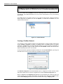
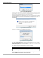
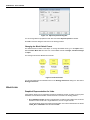
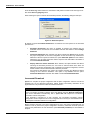
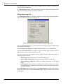
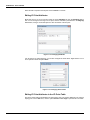
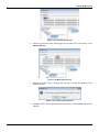
Select the configuration file that will be converted and click Open. See the example below:

User Interface
2.3
Figure 2.4. Selecting the SE Area
NOTE
A SE area may have two or more bridges. When converting this type of area, each bridge DF51
is replaced with the DF63, respecting the topology of the channels and devices connected to
each H1 channel.
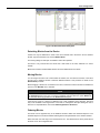
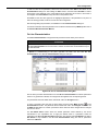
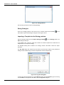
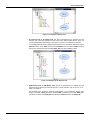
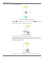
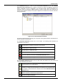
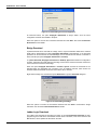
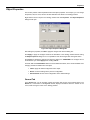
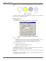
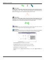
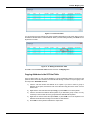
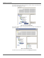
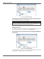
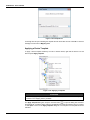
Wait a few seconds while the strategy configuration is converted. The new area with the DF63 is
displayed in Syscon.
Figure 2.5. Converting a SE Area
The file Syscon.ini has a section named Default ReplacementSeToHse, which indicates the
correspondence of old blocks in the DF51 that should be replaced by DF63 blocks.
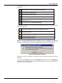
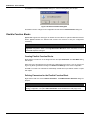
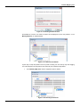
For each converted block during the bridge replacement, Syscon creates a log file in XML format
that contains the discrepancies between blocks. These XML files are stored in the folder
corresponding to the current configuration.
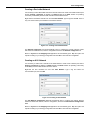
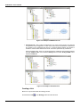
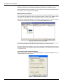
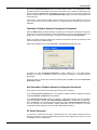
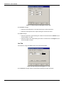
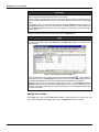
To open the XML file of a block, go to the File menu and select the option Exchange XML Viewer
to open a dialog box and select the XML file. See the example below:
Figure 2.6. XML log files for blocks

SYSCON 6.5 - User’s Manual
2.4
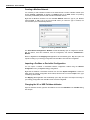
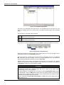
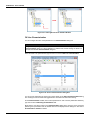
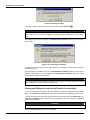
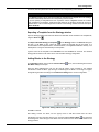
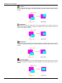
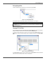
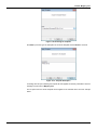
Select the icon of the desired file and click Open. The XML Viewer window shows the alterations
made to convert the strategy configuration, that is, attributes that were replaced in the new bridge
and blocks that had to be deleted. Select the icon of a block to see the details about compatible and
non-compatible parameters.
Figure 2.7. XML Viewer Window
Refer to subsection Using the XML Viewer Window at the end of this section for further details
about the XML Viewer window.
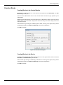
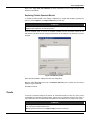
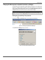
Creating an Area from a Template
You can create an area from a HSE template. This file will be automatically created with the HSE
Host, the bridges and devices, the resource and transducer blocks for each device, and the Flexible
Function Blocks.
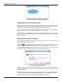
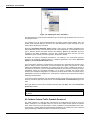
Click New on the main toolbar and select the option Predefined Area. The New Area dialog
box will show the list of templates available for each linking device. Click each template icon to view
the details and attributes:
Figure 2.8. Predefined Areas

User Interface
2.5
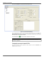
Select the icon of the area template and click Ok. The Setup New Area dialog box will open. Type
the name for the area and click Save.
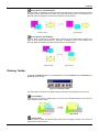
The main window will open and the selected strategy configuration will be displayed. The figure
below shows the example for the template DF62 Linking Device HSE 4xH1 FF:
Figure 2.9. Example of an area template
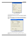
IMPORTANT
Syscon users can not create predefined area templates. Templates are defined by the devices’
manufacturers.
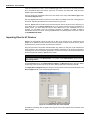
Opening an Area
To open an existing area, click Open on the main toolbar. The Open dialog box will appear.
Click the area icon and click Open.
NOTE
Depending on the number of blocks and devices included in an area, Syscon may take a few
minutes to open the strategy configuration.
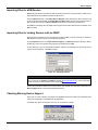
Checking the version
Starting from version 5.10, Syscon verifies if the strategy configuration was generated by previous
or later versions. If you are trying to open a strategy configuration generated in an older Syscon
version, the following message will open:
Figure 2.10. Version Mismatch Message Box

SYSCON 6.5 - User’s Manual
2.6
To upgrade the configuration, go to the File menu and click Save as, typing a new name for the
area or using the same name to override the old area.
If you upgrade the configuration converting it to the new file format, it won't be possible to open the
configuration in an older Syscon version again.
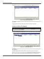
If Syscon detects that you are trying to open a strategy configuration that was generated in a newer
version, the following message will open:
Figure 2.11. Version Mismatch Message Box
IMPORTANT
Versions prior to 5.10 do not verify the strategy configuration. Those versions will open the area
generated in a newer version causing no error warnings, but the consistency of the configuration
will not be assured.
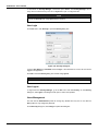
Saving an Area
To save the changes made to the strategy configuration or any of its parts, such as the Process Cell
window or the Strategy window, click Save on the main toolbar.
NOTE
The template
is not part of the plant configuration. It is necessary to set the focus on the
Template window and click Save to save the changes made to the template configuration.
Creating a Copy of the Area
To create a backup copy or rename the area, go to the File menu and click Save as. Type a new
name for the area and click Save. A new folder will be created with the name of the area and the
related files will be stored in this folder.
IMPORTANT
This option will only be available in Advanced Mode. The copy of the configuration file will be
saved in the local machine, when Syscon is operating in Multi-User mode.
This copy of the configuration file will no longer be managed by the Database Manager. A
message box will indicate that the user will be working in the Stand Alone mode. Mapping Tool
and FFB procedures will not be available in the Stand Alone mode.
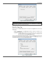
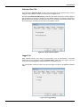
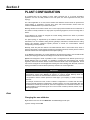
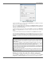
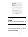
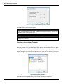
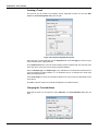
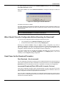
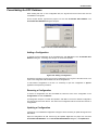
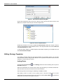
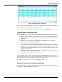
Printing the Strategy Configuration
From the File menu, click the option Printer Setup to open the Page Setup dialog box to set
personal printing preferences. These preferences include the page orientation, the tray from which
paper is sent, and the number of copies printed.
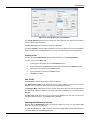
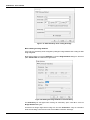
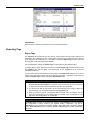
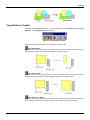
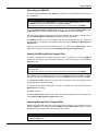
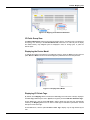
Printing the configuration file
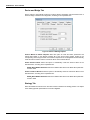
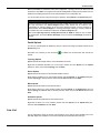
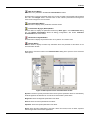
Select the main window and click the button Print on the main toolbar. The Print Configuration
dialog box will open. Select the items from the area to be printed:

User Interface
2.7
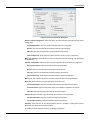
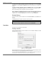
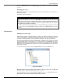
Figure 2.12. Print Configuration Dialog Box
Process Control Configuration: Select this item to print the information about the Process Control
Configuration.
General Information: prints the general information about the configuration.
Blocks: prints the information about the blocks, listed by control modules.
FB Links: prints the information about the links between those blocks.
Other Components: prints further information about the Process Control Configuration.
Multi Link Topology: Select this item to print the information about the topology, with the bridges
and fieldbuses.
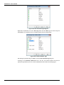
Fieldbus Configuration: Select this item to print the information about the Fieldbus Configuration.
General Information: prints the information about the configuration.
Blocks: prints the information about the blocks, listed by devices.
FB Links: prints the information about the links between those blocks.
Other Components: prints further information about the Fieldbus Configuration.
Device List: Select this item to print the information about the devices and their attributes.
Block List: Select this item to print the information about the blocks.
General Information: prints the information about blocks, their attributes and location.
Parameter Values: prints the information about the parameters configured for the blocks.
FB Links: prints the information about the connected parameters.
FB Link List: Select this item to print the list with all of the links in the configuration.
General Information: prints the general information about the links.
Connected Parameter: prints the information about the parameters.
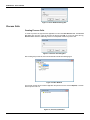
Schedule: Select this item to print the information about the Schedule, including both Function
Block Execution Schedule and Traffic Schedule.
Click Ok to close this dialog box and print the strategy configuration.

SYSCON 6.5 - User’s Manual
2.8
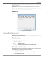
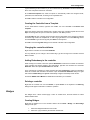
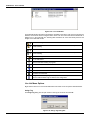
Printing the control strategy drawing
Select the Strategy window and click the button Print on the main toolbar. Configure the printer
options and click Ok to print the control strategy.
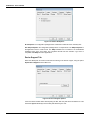
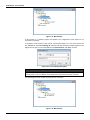
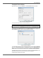
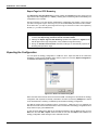
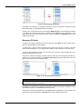
Print the configuration to a file
This option is only available when you select the main window. Go to the File menu and click Print
to File. The Print Configuration dialog box will open. Select the items from the area to be printed,
as described above, and click Ok.
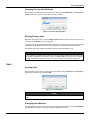
Then, the Save As dialog box will open. Select the folder to save the file, type the file name and
click Save. The file will be saved as a Report File in the txt format.
To print this file, open the Windows Explorer window and locate the file. Then right-click the file icon
and click Print. The strategy configuration will be printed.
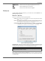
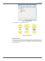
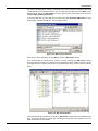
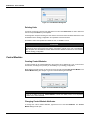
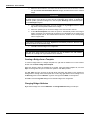
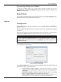
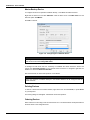
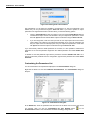
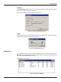
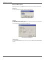
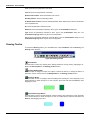
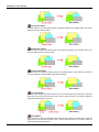
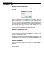
Print Preview
This option allows you to view the configuration report before printing it. Go to the File menu and
click Print Preview, or click the Print Preview button on the main toolbar. It will be necessary
to select the items from the area to be printed on the Print Configuration dialog box. Click Ok and
the Preview window will open.
Figure 2.13. Print Preview: Strategy Configuration
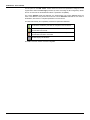
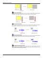
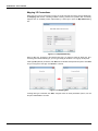
On the Preview window toolbar:
Shows the previous page.
Shows the next page.
Shows the entire page on the screen.
Shows two pages at the same time on the screen.
Activates the Zoom tool. Click the page to zoom in.
Deactivates the Zoom tool. Click the page to zoom out.
Page is loading ...
Page is loading ...
Page is loading ...
Page is loading ...
Page is loading ...
Page is loading ...
Page is loading ...
Page is loading ...
Page is loading ...
Page is loading ...
Page is loading ...
Page is loading ...
Page is loading ...
Page is loading ...
Page is loading ...
Page is loading ...
Page is loading ...
Page is loading ...
Page is loading ...
Page is loading ...
Page is loading ...
Page is loading ...
Page is loading ...
Page is loading ...
Page is loading ...
Page is loading ...
Page is loading ...
Page is loading ...
Page is loading ...
Page is loading ...
Page is loading ...
Page is loading ...
Page is loading ...
Page is loading ...
Page is loading ...
Page is loading ...
Page is loading ...
Page is loading ...
Page is loading ...
Page is loading ...
Page is loading ...
Page is loading ...
Page is loading ...
Page is loading ...
Page is loading ...
Page is loading ...
Page is loading ...
Page is loading ...
Page is loading ...
Page is loading ...
Page is loading ...
Page is loading ...
Page is loading ...
Page is loading ...
Page is loading ...
Page is loading ...
Page is loading ...
Page is loading ...
Page is loading ...
Page is loading ...
Page is loading ...
Page is loading ...
Page is loading ...
Page is loading ...
Page is loading ...
Page is loading ...
Page is loading ...
Page is loading ...
Page is loading ...
Page is loading ...
Page is loading ...
Page is loading ...
Page is loading ...
Page is loading ...
Page is loading ...
Page is loading ...
Page is loading ...
Page is loading ...
Page is loading ...
Page is loading ...
Page is loading ...
Page is loading ...
Page is loading ...
Page is loading ...
Page is loading ...
Page is loading ...
Page is loading ...
Page is loading ...
Page is loading ...
Page is loading ...
Page is loading ...
Page is loading ...
Page is loading ...
Page is loading ...
Page is loading ...
Page is loading ...
Page is loading ...
Page is loading ...
Page is loading ...
Page is loading ...
Page is loading ...
Page is loading ...
Page is loading ...
Page is loading ...
Page is loading ...
Page is loading ...
Page is loading ...
Page is loading ...
Page is loading ...
Page is loading ...
Page is loading ...
Page is loading ...
Page is loading ...
Page is loading ...
Page is loading ...
Page is loading ...
Page is loading ...
Page is loading ...
Page is loading ...
Page is loading ...
Page is loading ...
Page is loading ...
Page is loading ...
Page is loading ...
Page is loading ...
Page is loading ...
Page is loading ...
Page is loading ...
Page is loading ...
Page is loading ...
Page is loading ...
Page is loading ...
Page is loading ...
Page is loading ...
Page is loading ...
Page is loading ...
Page is loading ...
Page is loading ...
Page is loading ...
Page is loading ...
Page is loading ...
Page is loading ...
Page is loading ...
Page is loading ...
Page is loading ...
Page is loading ...
Page is loading ...
Page is loading ...
Page is loading ...
Page is loading ...
Page is loading ...
Page is loading ...
Page is loading ...
Page is loading ...
Page is loading ...
Page is loading ...
Page is loading ...
Page is loading ...
-
 1
1
-
 2
2
-
 3
3
-
 4
4
-
 5
5
-
 6
6
-
 7
7
-
 8
8
-
 9
9
-
 10
10
-
 11
11
-
 12
12
-
 13
13
-
 14
14
-
 15
15
-
 16
16
-
 17
17
-
 18
18
-
 19
19
-
 20
20
-
 21
21
-
 22
22
-
 23
23
-
 24
24
-
 25
25
-
 26
26
-
 27
27
-
 28
28
-
 29
29
-
 30
30
-
 31
31
-
 32
32
-
 33
33
-
 34
34
-
 35
35
-
 36
36
-
 37
37
-
 38
38
-
 39
39
-
 40
40
-
 41
41
-
 42
42
-
 43
43
-
 44
44
-
 45
45
-
 46
46
-
 47
47
-
 48
48
-
 49
49
-
 50
50
-
 51
51
-
 52
52
-
 53
53
-
 54
54
-
 55
55
-
 56
56
-
 57
57
-
 58
58
-
 59
59
-
 60
60
-
 61
61
-
 62
62
-
 63
63
-
 64
64
-
 65
65
-
 66
66
-
 67
67
-
 68
68
-
 69
69
-
 70
70
-
 71
71
-
 72
72
-
 73
73
-
 74
74
-
 75
75
-
 76
76
-
 77
77
-
 78
78
-
 79
79
-
 80
80
-
 81
81
-
 82
82
-
 83
83
-
 84
84
-
 85
85
-
 86
86
-
 87
87
-
 88
88
-
 89
89
-
 90
90
-
 91
91
-
 92
92
-
 93
93
-
 94
94
-
 95
95
-
 96
96
-
 97
97
-
 98
98
-
 99
99
-
 100
100
-
 101
101
-
 102
102
-
 103
103
-
 104
104
-
 105
105
-
 106
106
-
 107
107
-
 108
108
-
 109
109
-
 110
110
-
 111
111
-
 112
112
-
 113
113
-
 114
114
-
 115
115
-
 116
116
-
 117
117
-
 118
118
-
 119
119
-
 120
120
-
 121
121
-
 122
122
-
 123
123
-
 124
124
-
 125
125
-
 126
126
-
 127
127
-
 128
128
-
 129
129
-
 130
130
-
 131
131
-
 132
132
-
 133
133
-
 134
134
-
 135
135
-
 136
136
-
 137
137
-
 138
138
-
 139
139
-
 140
140
-
 141
141
-
 142
142
-
 143
143
-
 144
144
-
 145
145
-
 146
146
-
 147
147
-
 148
148
-
 149
149
-
 150
150
-
 151
151
-
 152
152
-
 153
153
-
 154
154
-
 155
155
-
 156
156
-
 157
157
-
 158
158
-
 159
159
-
 160
160
-
 161
161
-
 162
162
-
 163
163
-
 164
164
-
 165
165
-
 166
166
-
 167
167
-
 168
168
-
 169
169
-
 170
170
-
 171
171
-
 172
172
-
 173
173
-
 174
174
-
 175
175
-
 176
176
-
 177
177
-
 178
178


Ask a question and I''ll find the answer in the document
Finding information in a document is now easier with AI
Related papers
Other documents
-
Johnson Controls OpenBlue Industrial Refrigeration User guide
-
 Thermo Fisher Scientific Application User guide
-
Pro-face BLUE Open Studio 2023 Owner's manual
-
DigiTech Element User manual
-
Xerox DigiPath Professional Production Software Administration Guide
-
Eurotherm Suite Project Organiser User guide
-
Sierra 600/700 Series Profibus DP User manual
-
dbx 442 Owner's manual
-
-
