


Introduction
III
INTRODUCTION
This manual is divided in three parts:
- Ladder Logic: The control elements of a control strategy available in the CONF700 and used
by the CPU-700 are described in this chapter.
- Function Blocks: We present detailed descriptions of all function blocks available in the
CONF700 and used by the CPU-700.
- CONF700: We describe Smar’s Software CONF700. This is the application used to configure
the hardware of a control system (I/O Modules, Power Supplies, CPU, etc), mplement ladder logic
(including ladder network elements and function blocks)
We suggest the user to read initially Chapters 1 and 2 and next go to Chapter 3 that describes
clearly how to implement the elements described in the first two Chapters. However, the user is free
to start reading from Chapter 3 prior to the other ones and consult Chapters 1 and 2 any time it is
necessary while reading of Chapter 3. Chapter 3 deals with description of the Smar’s CONF700
Software that is part of the LC700 System.
Chapter 4 Troubleshooting brings solutions to problems found by users by configure the LC700
system.
This manual has practical examples that describe step-by-step how to set strategies of control.
These examples were included in order to make easier the user’s understanding of the system.
These applications are distributed along this manual.

LC700 Configuration Manual
IV
NOTE
The CONF700 version 8 only reads and converts configurations made in previous versions of the
CONF700. The CONF700 version 8 only supports CPU-700-D3, CPU-700-D3R, CPU-700-E3, CPU-
700-E3R, RIO-700-D3 and RIO-700-E3.
The configuration file updates versions previous to PL4 will caus
e changes in the MODBUS
Addresses, however the configuration files higher than PL4 will not have these changes.
NOTE
This document is a description of all function blocks and logic elements (ladder) implemented in the
logic programmable
controller (LC700). Besides this document presents a description of how to
configure and edit ladder networks through Smar’s CONF700. This document also describes details of
this software.
Smar reserves it the right to change any part of this manual without prior notice.
Note that different versions of the LC700 have different types of data, function blocks and generic
characteristics. The last version of the LC700 is always an update of the old manual without prior
notice. It means it will have all characteristics included, old and new ones.

Table of Contents
V
TABLE OF CONTENTS
SECTION 1 - NETWORK ELEMENTS (LADDER ELEMENTS) AND TOOLS .......................................... 1.1
NETWORK ELEMENTS ..................................................................................................................................................... 1.1
DEFINITIONS FOR THE NETWORK TOOL BOX ELEMENTS ......................................................................................... 1.1
NORMALLY OPEN CONTACT ................................................................................................................................................. 1.1
NORMALLY CLOSED CONTACT ............................................................................................................................................ 1.1
POSITIVE TRANSITION-SENSING CONTACT ....................................................................................................................... 1.1
NEGATIVE TRANSITION-SENSING CONTACT ..................................................................................................................... 1.2
COIL ......................................................................................................................................................................................... 1.2
NEGATED COIL ....................................................................................................................................................................... 1.2
SET (LATCH) COIL .................................................................................................................................................................. 1.2
RESET (UNLATCH) COIL ........................................................................................................................................................ 1.2
RETENTIVE (MEMORY) COIL ................................................................................................................................................. 1.2
SET RETENTIVE (MEMORY) COIL ......................................................................................................................................... 1.2
RESET RETENTIVE (MEMORY) COIL .................................................................................................................................... 1.2
POSITIVE TRANSITION-SENSING COIL ................................................................................................................................ 1.3
NEGATIVE TRANSITION-SENSING COIL .............................................................................................................................. 1.3
HORIZONTAL CONNECTING LINE ......................................................................................................................................... 1.3
VERTICAL CONNECTING LINE .............................................................................................................................................. 1.3
ELIMINATE VERTICAL CONNECTING LINE FROM THE FOCUSED CELL .......................................................................... 1.3
FUNCTION BLOCKS ................................................................................................................................................................ 1.3
USER FUNCTION .................................................................................................................................................................... 1.3
JUMP TO A NETWORK ........................................................................................................................................................... 1.3
RETURN FOR THE LAST JUMP ............................................................................................................................................. 1.3
BOOLEAN LOGIC .............................................................................................................................................................. 1.4
NORMALLY OPEN RELAY ...................................................................................................................................................... 1.4
NORMALLY CLOSED RELAY .................................................................................................................................................. 1.4
LOGICAL FUNCTION OR ........................................................................................................................................................ 1.4
LOGICAL FUNCTION AND ...................................................................................................................................................... 1.4
BOOLEAN EQUATIONS .......................................................................................................................................................... 1.5
BOOLEAN ALGEBRA............................................................................................................................................................... 1.5
SECTION 2 - FUNCTION BLOCKS .......................................................................................................... 2.1
INTRODUCTION ................................................................................................................................................................ 2.1
EN INPUT AND ENO OUTPUT .......................................................................................................................................... 2.1
AVAILABLE FUNCTION BLOCKS IN ALPHABETIC ORDER ........................................................................................... 2.2
FUNCTION BLOCKS LISTED BY FUNCTIONAL GROUPS ............................................................................................. 2.3
TIME AND PULSE RELATED FUNCTIONS ............................................................................................................................. 2.3
DATA MANIPULATION FUNCTIONS....................................................................................................................................... 2.3
MATHEMATICAL FUNCTIONS ................................................................................................................................................ 2.3
COMPARISON FUNCTIONS ................................................................................................................................................... 2.4
PROCESS CONTROL FUNCTIONS ........................................................................................................................................ 2.4
TIME AND PULSE RELATED FUNCTIONS ...................................................................................................................... 2.5
ACC - PULSE ACCUMULATOR ............................................................................................................................................... 2.5
ACC_N - PULSE ACCUMULATOR .......................................................................................................................................... 2.7
CTD - PULSE COUNTER DOWN ............................................................................................................................................ 2.9
CTU - PULSE COUNTER UP ................................................................................................................................................. 2.10
CTU1 - PULSE COUNTER UP ............................................................................................................................................... 2.11
RTA - REAL TIME ALARM ..................................................................................................................................................... 2.12
TOF - TIMER OFF-DELAY ..................................................................................................................................................... 2.14
TOF1 - TIMER OFF-DELAY ................................................................................................................................................... 2.16
TON - TIMER ON-DELAY ....................................................................................................................................................... 2.17
TON1 - TIMER ON-DELAY ..................................................................................................................................................... 2.19
TP - TIMER PULSE ................................................................................................................................................................ 2.20
TP1 - TIMER PULSE .............................................................................................................................................................. 2.22
DATA MANIPULATION FUNCTIONS .............................................................................................................................. 2.23
BTB - BYTE TO BITS CONVERSION .................................................................................................................................... 2.23
BTI - BCD TO INTEGER CONVERSION ................................................................................................................................ 2.24
FIFO - FIRST IN-FIRST OUT ................................................................................................................................................. 2.25
ICT - INTEGER CONSTANTS ................................................................................................................................................ 2.28
ITB - INTEGER TO BCD CONVERSION ................................................................................................................................ 2.29
ITR - INTEGER TO REAL CONVERSION .............................................................................................................................. 2.30
MUX - MULTIPLEXER ............................................................................................................................................................ 2.31

LC700 Configuration Manual
VI
NOT - BITWISE NOT .............................................................................................................................................................. 2.32
OSEL - OUTPUT BINARY SELECTION ................................................................................................................................. 2.33
RCT - REAL CONSTANTS ..................................................................................................................................................... 2.34
RTI - REAL TO INTEGER CONVERSION .............................................................................................................................. 2.35
SEL - BINARY SELECTION ................................................................................................................................................... 2.36
TRC - TRUNCATE .................................................................................................................................................................. 2.37
BWL - BIT WISE LOGIC ......................................................................................................................................................... 2.38
MATHEMATICAL FUNCTIONS ....................................................................................................................................... 2.41
ABS - ABSOLUTE VALUE ...................................................................................................................................................... 2.41
ADD - ADDITION .................................................................................................................................................................... 2.42
DIV - DIVISION ....................................................................................................................................................................... 2.43
MOD - MODULO .................................................................................................................................................................... 2.44
MUL - MULTIPLICATION ....................................................................................................................................................... 2.45
SQR - SQUARE ROOT .......................................................................................................................................................... 2.46
SUB - SUBTRACTION ............................................................................................................................................................ 2.47
COMPARISON FUNCTIONS ........................................................................................................................................... 2.48
EQ - EQUALITY ...................................................................................................................................................................... 2.48
GE - DECREASING MONOTONIC SEQUENCE ................................................................................................................... 2.49
GT - DECREASING SEQUENCE ........................................................................................................................................... 2.50
LE - INCREASING MONOTONIC SEQUENCE ...................................................................................................................... 2.51
LMT - LIMITER ....................................................................................................................................................................... 2.52
LT - INCREASING SEQUENCE ............................................................................................................................................. 2.53
MAX - MAXIMUM ................................................................................................................................................................... 2.54
MIN - MINIMUM ...................................................................................................................................................................... 2.55
NE - INEQUALITY .................................................................................................................................................................. 2.56
PROCESS CONTROL FUNCTIONS ............................................................................................................................... 2.57
XLIM- CROSS LIMIT AND RATE-OF-CHANGE ..................................................................................................................... 2.57
TOT - TOTALIZATION ............................................................................................................................................................ 2.59
SMPL - SAMPLE HOLD WITH UP AND DOWN .................................................................................................................... 2.61
ARAMP - AUTOMATIC UP AND DOWN RAMP ..................................................................................................................... 2.62
LIN - LINEARIZATION ............................................................................................................................................................ 2.64
MATH1 - MULTIVARIABLE EQUATIONS .............................................................................................................................. 2.66
PID - PID CONTROLLER ....................................................................................................................................................... 2.71
STATUS - SYSTEM STATUS ................................................................................................................................................. 2.75
STP - STEP CONTROL .......................................................................................................................................................... 2.80
SECTION 3 - THE CONF700 .................................................................................................................... 3.1
INTRODUCTION ................................................................................................................................................................ 3.1
INSTALLATION .................................................................................................................................................................. 3.1
OPERATING SYSTEM ............................................................................................................................................................. 3.1
USING THE CONF700 ....................................................................................................................................................... 3.2
LAUNCHING THE APPLICATION ............................................................................................................................................ 3.2
PROJECT INFORMATION ....................................................................................................................................................... 3.2
WORKING DIRECTORY .................................................................................................................................................... 3.3
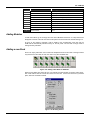
SETTING UP THE I/O MODULES ............................................................................................................................................ 3.4
ADDING MODULES ................................................................................................................................................................. 3.5
SPECIAL MODULES ................................................................................................................................................................ 3.5
CONFIGURATION AND HARDWARE CONSISTENCY........................................................................................................... 3.6
EDITING THE I/O MODULES ................................................................................................................................................... 3.7
SPECIAL I/O MODULES .................................................................................................................................................... 3.7
CONFIGURING THE M-401-DR MODULES ............................................................................................................................ 3.7
CONFIGURING THE M-402 TEMPERATURE MODULE ......................................................................................................... 3.8
CONFIGURING THE M-501 MODULE ..................................................................................................................................... 3.9
CONFIGURING THE FB-700 MODULE ................................................................................................................................. 3.10
THE BALANCE SHEET .......................................................................................................................................................... 3.12
ID AND THE MODULES .................................................................................................................................................. 3.13
A NOTE ABOUT THE CUT, PASTE, AND MOVE TOOLS .............................................................................................. 3.14
CUT AND PASTE ................................................................................................................................................................... 3.14
MOVE ..................................................................................................................................................................................... 3.15
UNDO ............................................................................................................................................................................... 3.15
MEMORY ALLOCATION .................................................................................................................................................. 3.16
ADDING MODULES ......................................................................................................................................................... 3.17
ADDING A NEW RACK .................................................................................................................................................... 3.17
REMOTE-I/O SUBSYSTEM ............................................................................................................................................. 3.18
RIO LIMITS ............................................................................................................................................................................. 3.18

Table of Contents
VII
GLOBAL TABLE ............................................................................................................................................................... 3.18
FAIL/SAFE OUTPUTS ............................................................................................................................................................ 3.19
CONFIGURING VIRTUAL MODULES (DISCRETE MEMORY LOCATIONS) ................................................................ 3.20
USER TAGS AND DESCRIPTION FOR VIRTUAL POINTS .................................................................................................. 3.21
CONFIGURING THE CONTROL STRATEGY ................................................................................................................. 3.23
LADDER DIAGRAMS (LADDER NETWORKS) ...................................................................................................................... 3.23
THE LOGIC NETWORK ......................................................................................................................................................... 3.23
THE COMPLETE CYCLE OF THE LC700 ............................................................................................................................. 3.23
SYNCHRONIZED LADDER LOGIC EXECUTION AND COMMUNICATION ......................................................................... 3.24
EXECUTION SEQUENCE OF A LOGIC NETWORK ............................................................................................................. 3.24
LOGIC NETWORK EDITING PREFERENCES ...................................................................................................................... 3.24
MANAGING MULTIPLE LOGIC NETWORKS ........................................................................................................................ 3.24
MOVING FROM ONE LOGIC NETWORK TO THE OTHER .................................................................................................. 3.25
INSERTING LADDER DIAGRAM ELEMENTS ....................................................................................................................... 3.25
INSERTING FUNCTION BLOCKS ......................................................................................................................................... 3.28
DELETING ELEMENTS WITH THE BUTTON DELETE ......................................................................................................... 3.31
FUNCTION BLOCKS LINKS .................................................................................................................................................. 3.31
PID LOOP AUTOMATIC/MANUAL OPERATION ................................................................................................................... 3.31
PID LOOP SETPOINT OPERATION ...................................................................................................................................... 3.35
GENERAL HINTS ON THE NETWORK ................................................................................................................................. 3.37
FINDING THINGS IN THE NETWORKS .......................................................................................................................... 3.37
USING THE I/O FIND OPTION .............................................................................................................................................. 3.39
THE USER FUNCTION FIND TAB ......................................................................................................................................... 3.41
THE FUNCTION BLOCKS FIND TAB .................................................................................................................................... 3.42
ADDING NOTES TO THE LADDER LOGIC PROGRAMMING LINES ............................................................................ 3.42
CONFIGURATION MEMORY USAGE AND EXECUTION TIME ESTIMATION ............................................................. 3.43
CPU MEMORY ....................................................................................................................................................................... 3.43
I/O MODULES ........................................................................................................................................................................ 3.44
THE NETWORK (LADDER DIAGRAM) ........................................................................................................................... 3.45
FUNCTION BLOCKS .............................................................................................................................................................. 3.47
CONNECTING TO THE LC700 ........................................................................................................................................ 3.49
CABLE .................................................................................................................................................................................... 3.49
COMMUNICATION SWITCH .................................................................................................................................................. 3.50
PHYSICAL LAYER AND TIME OUT ....................................................................................................................................... 3.50
CHANGING THE CPU-700 COMMUNICATION SETTINGS .................................................................................................. 3.51
CHANGING THE LC700 COMMUNICATION PARAMETERS ............................................................................................... 3.52
COMMUNICATION OPTIMIZED ............................................................................................................................................ 3.54
MODBUS MESSAGE FRAMING ..................................................................................................................................... 3.54
LIST OF IMPLEMENTED MODBUS COMMANDS .......................................................................................................... 3.55
ETHERNET COMMUNICATION SETTINGS ................................................................................................................... 3.55
TIME OUT FOR THE LAN ...................................................................................................................................................... 3.55
ENET-700/ENET-710 IP ADDRESS ....................................................................................................................................... 3.56
USING ENET-700 ................................................................................................................................................................... 3.56
USING ENET-710 ................................................................................................................................................................... 3.58
SETTING THE TIME OUT FOR ENET-700/ENET-710 .......................................................................................................... 3.61
WORKING ON-LINE ........................................................................................................................................................ 3.62
DOWNLOADING THE CONFIGURATION ............................................................................................................................. 3.62
ON-LINE MONITORING ................................................................................................................................................... 3.63
CPU700 IN THE RUN MODE ................................................................................................................................................. 3.64
MONITORING FUNCTION BLOCKS AND LADDER ELEMENTS STATE ............................................................................. 3.64
MONITOR NETWORKS ......................................................................................................................................................... 3.64
MONITORING SPEED ........................................................................................................................................................... 3.65
BLOCK I/O MONITORING ...................................................................................................................................................... 3.65
FORCING ELEMENTS ........................................................................................................................................................... 3.65
USING THE MONITORING FEATURE IN THE MODBUS ADDRESSES PAGE ................................................................... 3.65
ONLINE MODE ................................................................................................................................................................ 3.67
ONLINE EDITING ............................................................................................................................................................. 3.68
HOW IT WORKS? .................................................................................................................................................................. 3.69
THE ONLINE EDITING BUTTONS ......................................................................................................................................... 3.69
FULL ONLINE EDITION ................................................................................................................................................... 3.69
IMPORTANT INFORMATION TO BE CONSIDERED BEFORE USING THE FULL ONLINE EDITION MODE ..................... 3.69
USING THE FULL ONLINE EDITION ..................................................................................................................................... 3.70
ADD/CHANGE LADDER ELEMENTS .................................................................................................................................... 3.72
ADD/REMOVE NETWORKS .................................................................................................................................................. 3.73
ADD/REMOVE MODULES ..................................................................................................................................................... 3.74

LC700 Configuration Manual
VIII
ADD/REMOVE VIRTUAL MODULES ..................................................................................................................................... 3.76
ADD/REMOVE RIO INTERFACE ........................................................................................................................................... 3.77
ADD/REMOVE USER FUNCTIONS ....................................................................................................................................... 3.77
CHANGE MODULE CONFIGURATION ................................................................................................................................. 3.78
MOVE MODULES IN THE MODULE PAGE ........................................................................................................................... 3.78
UPDATE IN THE FULL ONLINE EDITION ............................................................................................................................. 3.79
SYSTEM TEST AFTER THE UPDATE ................................................................................................................................... 3.81
DIFFERENTIAL DOWNLOAD .......................................................................................................................................... 3.82
1º STEP .................................................................................................................................................................................. 3.82
CONDITION TABLE ............................................................................................................................................................... 3.82
RULES: ................................................................................................................................................................................... 3.82
2º STEP .................................................................................................................................................................................. 3.83
3º STEP: ................................................................................................................................................................................. 3.84
4º STEP .................................................................................................................................................................................. 3.84
CASE 1: CPU-700 IS CONNECTED TO THE PC .................................................................................................................. 3.84
CASE 2: CPU-700 IS NOT CONNECTED TO THE PC OR IS DESIRED TO SEND THE CHANGE LATE. .......................... 3.84
DIFFERENCES BETWEEN ONLINE EDITION AND FULL ONLINE EDITION ............................................................... 3.87
FULL ONLINE EDITION ADVANTAGES ......................................................................................................................... 3.87
NOTES ................................................................................................................................................................................... 3.87
NOTE FOR M-402 MODULE .................................................................................................................................................. 3.87
NOTE FOR FB-700 MODULE ................................................................................................................................................ 3.87
NOTE FOR BLOCK VIEW COMMUNICATION ...................................................................................................................... 3.88
COMMUNICATION FAILURES ........................................................................................................................................ 3.88
A) BEFORE USING THE SEND BUTTON ............................................................................................................................. 3.88
B) AFTER USING THE SEND BUTTON ................................................................................................................................ 3.88
B.1) THE CPU DOES NOT STILL HAVE THE NEW CONFIGURATION ............................................................................... 3.88
B.2) THE CPU ALREADY HAS THE NEW CONFIGURATION .............................................................................................. 3.89
C) AFTER USING THE ACCEPT CHANGES BUTTON ......................................................................................................... 3.90
UPDATE DESISTANCE IN THE FULL ONLINE EDITION .............................................................................................. 3.90
EXAMPLE FOR FULL ONLINE EDITION ........................................................................................................................ 3.92
EXAMPLE 1 ............................................................................................................................................................................ 3.92
B) EXAMPLE 2 ....................................................................................................................................................................... 3.97
CONNECTING THE LC700 TO AN HMI ........................................................................................................................ 3.100
OPC (OLE FOR PROCESS CONTROL) .............................................................................................................................. 3.100
USING COMMUNICATION DRIVERS WITH MODBUS ................................................................................................ 3.102
MODBUS COMMUNICATION .............................................................................................................................................. 3.102
MODBUS ADDRESS CODING ...................................................................................................................................... 3.103
IMPLICATIONS IN MODIFYING A LC700 CONFIGURATION ...................................................................................... 3.104
DIGITAL MEMORY MAP ...................................................................................................................................................... 3.104
ANALOG MEMORY MAP ..................................................................................................................................................... 3.104
SPECIAL REGISTERS ................................................................................................................................................... 3.105
READYSCANRIO ................................................................................................................................................................. 3.105
SSIOSTATUS ....................................................................................................................................................................... 3.105
MANUAL MODBUS ADDRESSES ATTRIBUTION ........................................................................................................ 3.106
AUTOMATIC MODBUS ADDRESS ALLOCATION .............................................................................................................. 3.106
MANUAL MODBUS ADDRESS ALLOCATION .................................................................................................................... 3.106
I/O MODULE MODBUS ADDRESS ALLOCATION .............................................................................................................. 3.107
FUNCTION BLOCK MODBUS ADDRESS ALLOCATION: ................................................................................................... 3.108
USER FUNCTION BLOCKS .......................................................................................................................................... 3.109
INTRODUCTION .................................................................................................................................................................. 3.109
CREATING AN USER FUNCTION ....................................................................................................................................... 3.109
WARNING MESSAGES ....................................................................................................................................................... 3.113
HOW TO ESTIMATE MEMORY SPACE USED BY USER FUNCTIONS............................................................................. 3.114
EDITING AN USER FUNCTION ........................................................................................................................................... 3.115
OPTIMIZING HARDWARE FOR AN APPLICATION ..................................................................................................... 3.115
SECTION 4 - HELP FOR PLANT STARTUP WITH THE LC700 .............................................................. 4.1
1) COMMUNICATION PARAMETERS .............................................................................................................................. 4.1
2) TIME OUTS .................................................................................................................................................................... 4.1
CONSIDERATIONS ........................................................................................................................................................... 4.3
SECTION 5 - TROUBLESHOOTING ........................................................................................................ 5.1
APPENDIX A - FSR – SERVICE REQUEST FORM ................................................................................ A.1

Chapter 1
1.1
NETWORK ELEMENTS (LADDER
ELEMENTS) AND TOOLS
This section will help the user understand the meaning of the network ladder elements and the
network tools.
¾ The Network Elements
¾ The Label Dialog Box
Network Elements
As mentioned before, CONF700 uses symbols and notations defined in the standard IEC-61131-3.
Network Tool Box
Definitions for the Network Tool Box Elements
Normally Open Contact
The state of the left link is copied to the right link if the state of the Boolean variable is ON.
Otherwise, the state of the right link is OFF.
Normally Closed Contact
The state of the left link is copied to the right link if the state of the Boolean variable is OFF.
Otherwise, the state of the right link is OFF.
Positive Transition-Sensing Contact
The state of the right link is ON from one evaluation of this element to the next when a transition of
the associated variable from OFF to ON is sensed at the same time that the state of the left link is
ON. The state of the right link shall be OFF at all other times.

LC700 Configuration Manual
1.2
Negative Transition-Sensing Contact
The state of the right link is ON from one evaluation of this element to the next when a transition of
the associated variable from ON to OFF is sensed at the same time the state of the left link is ON.
The state of the right link shall be OFF at all other times.
Coil
The state of the left link is copied to the associated Boolean variable and to the right link.
Negated Coil
The state of the left link is copied to the right link. The inverse of the state of the left link is copied to
the associated Boolean variable, that is, if the state of the left link is OFF, then the state of the
associated variable is ON, and vice versa.
Set (Latch) Coil
The associated Boolean variable is set to the ON state when the left link is in the ON state, and
remains set until reset by a RESET coil.
Reset (Unlatch) Coil
The associated Boolean variable is reset to the OFF state when the left link is in the ON state, and
remains reset until set again by a SET coil.
Retentive (Memory) Coil
The associated Boolean Variable will be retentive to the memory.
Note that the action of this coil is identical to Coil, except that the associated Boolean variable
is automatically declared to be in retentive memory without the explicit use of the VAR RETAIN
declaration defined in the initialization of variables in IEC-61131-3 standard.
Set Retentive (Memory) Coil
The associated Boolean variable is set to the ON state when the left link is in the ON state, and
remains set until reset by a RESET coil. The associated Boolean Variable will be retentive to the
memory.
Note that the action of this coil is identical to Set (Latch) Coil, except that the associated
Boolean variable is automatically declared to be in retentive memory without the explicit use of the
VAR RETAIN declaration defined in the initialization of variables in IEC-1131-3 standard.
Reset Retentive (Memory) Coil
The associated Boolean variable is reset to the OFF state when the left link is in the ON state, and
remains reset until set by a SET coil. The associated Boolean Variable will be retentive to the
memory.
Note that the action of this coil is identical to RESET (Unlatch) Coil, except that the associated

Network Elements (Ladder Elements) and Tools
1.3
Boolean variable is automatically declared to be in retentive memory without the explicit use of the
VAR RETAIN declaration defined in the initialization of variables in IEC-61131-3 standard.
Positive Transition-Sensing Coil
The state of the associated Boolean variable is ON from one evaluation of this element to the next
when a transition of the left link from OFF to ON is sensed. The state of the left link is always copied
to the right link.
Negative Transition-Sensing Coil
The state of the associated Boolean variable is ON from one evaluation of this element to the next
when a transition of the left link from ON to OFF is sensed. The state of the left link is always copied
to the right link.
Horizontal Connecting Line
Use this tool to draw a connecting line from left to right in the marked cell.
Vertical Connecting Line
Use this tool to draw a connecting line from the right side of the marked cell downward.
Eliminate Vertical Connecting Line from the Focused Cell
This tool eliminates the vertical connection line. Place the selection box in the element that has the
vertical line the user whishes to eliminate.
Function Blocks
Use this tool to open a Dialog Box for choosing the desired Built-in-Function.
User Function
Use this tool to open a Dialog Box for choosing available User-Functions.
Jump to a Network
If more than one Network is available, it will open a Dialog Box for choosing the desired Network.
Return for the Last Jump
Use this tool to return to the next executable cell preceding the last Jump. If no Jump has being
used, it will then be ignored.

LC700 Configuration Manual
1.4
Boolean Logic
The association of relays and coils creates boolean functions. Below a brief summary of these
functions and Boolean Algebra is presented.
Normally Open Relay
Diagram State Table
A S
0 0
1 1
When the state of A changes from 0 to 1, the contact A closes and the flow goes from the power rail
on the left to the right powering the coil S.
Normally Closed Relay
Diagram State Table
A S
0 1
1 0
The operation of a Normally Closed Relay is the same to that of a Normally Open Relay, except
backwards. That is, when the state of A changes from 0 to 1, the contact A opens and the current
does not flow from the power rail to the right. (through the contact A circuit)
Logical Function OR
Diagram State Table
A B S
0 0 0
0 1 1
1 0 1
1 1 1
Relays A and B are normally open. With the association of both we implement the OR function. The
coil is powered when any of the two relays is closed.
Logical Function AND
Diagram State Table
A B S
0 0 0
0 1 0
1 0 0
1 1 1
Relays A and B are normally open. The coil S is powered when A and B are equal to 1 at the same

Network Elements (Ladder Elements) and Tools
1.5
time. Otherwise, power will not flow from the left side (power rail) to the right side.
Boolean Equations
By using relays and coils it is possible to implement boolan functions. For example, consider the
diagram below:
The S output depends on the state of the relays A, B, C, D and on the coil E. E depends on the
values of A, B, C and D. So:
ES
B).(C).D(AE
=
+
=
Boolean Algebra
Boolean equations as shown above may become very complicated; however the result might be
simplified using the boolean algebra. Below is a summary of properties of the Boolean Algebra.
1 A.1= A
2 A.0= 0
3a
3b A.A= A
AA = 0
4a
4b A+A=1
A+A=A
5 A+1=1
6 A.B+A.C=A.(B+C)
7 A+A.B= A
8 A.(B+C)= A.B+A.C
9a
9b B.ABA =
+
BAA.B
+
=
When these expressions become too complex we suggest that you use the Karnaugh map in order
to simplify them. This information is easily found on any Digital Electronics Book.

LC700 Configuration Manual
1.6

Chapter 2
2.1
FUNCTION BLOCKS
Introduction
This is a complete and updated reference of the Function Blocks (FB) supported by the LC700 CPU.
Here we present block diagrams showing inputs, outputs, configuration parameters and internal
variables. It also includes detailed explanations of each block, how they work, how to configure each
one of them and a few examples are presented in order to help with the user’s understanding and
utilization.
Many times, an input or output will be classified as ANY, ANY_NUM, ANY_BIT, ANY_REAL or
ANY_INT. If input is ANY_NUM it means it might be connected to either a REAL or INT output. For
a better explanation, see the table below:
Reference Data Type Number of bits Version
BOOLEAN Boolean 1 1.xx or superior
INT Integer 16 2.xx or superior
REAL Float 32 2.xx or superior
WORD String 16 2.xx or superior
A
N
Y
A
N
Y
_
NUM
A
NY_BIT
A
N
Y
_
REAL
A
NY_IN
T
REAL
INT
BOOL
,
BYTE
If the user tries to set two outputs of a function block having variables of different data types, for
example, adding an integer to a float, the CONF700 will not allow this setting. As the first block
variable is selected, it is expected that all other inputs have the same data type of this variable.
During this configuration of inputs and outputs CONF700 asks the user to inform variable data types
that should be set when the manual describes it as ANY_XX.
Each function block has a table where all inputs, outputs, parameters and variables of each block
are shown.
I - Inputs: It is a variable from another FB or from an I/O card
P - Parameter: User’s configurations.
O - Outputs: Variables resulting from processing inside each block.
V - Variables: Auxiliary variables of block algorithms.
Information about using period “.” and comma “,” for the function blocks:
The format of writing the numeric data (using “.” and “,”) should be according to the local
configuration of the computer.
EN Input And ENO Output
Every function has an EN input and an ENO output.
EN input is set to enable the function block that should be processed. If EN is false, all outputs
change to zero and the FB is not executed.
ENO changes to true logic to indicate the function was successfully executed without troubles.

LC700 Configuration Manual
2.2
Available Function blocks in alphabetic order
The table below shows all the available function blocks.
FUNCTION NAME DESCRIPTION
ABS Absolute Value
ACC Pulse Accumulator
ACC_N Pulse Accumulator
ADD Addition
ARAMP Automatic Up And Down Ramp
BTB BYTE_TO_BITS Conversion
BTI BCD_TO_INT Conversion
BWL Bit wise Logic
CTD Counter Down
CTU Counter Up
CTU1 Counter Up
DIV Division
EQ Equality
FIFO First In First Out
GE Decreasing Monotonic Sequence
GT Decreasing Sequence
ICT Integer Constants
ITB INT-TO-BCD Conversion
ITR Conversion Int To Real
LE Increasing Monotonic Sequence
LIN Linearization
LMT Limiter
LT Increasing Sequence
MATH1 Multivariable Equations
MAX Maximum
MIN Minimum
MOD Modulo
MUL Multiplication
MUX Multiplexer
NE Inequality
NOT Bitwise NOT
OSEL Output Selection
PID PID Controller
RCT Real Constants
RTA Real Time Clock Alarm
RTI Conversion Real To Int
SEL Binary Selection
SMPL Sample Hold With Up And Down
SQR Square Root
STATUS System Status
STP Step Control
SUB Subtraction
TOF Timer Off-Delay
TOF1 Timer Off-Delay
TON Timer On-Delay
TON1 Timer On-Delay
TOT Totalization
TP Timer Pulse
TP1 Timer Pulse
TRC Truncation
XLIM Cross Limit And Rate-Of-Change

Function Blocks
2.3
Function Blocks listed by functional groups
Time and Pulse related Functions
TIME/PULSE FUNCTIONS
MNEMONIC DESCRIPTION
ACC Pulse Accumulator
ACC_N Pulse Accumulator
CTU1 Counter Up
TOF1 Timer Off-Delay
TON1 Timer On-Delay
TP1 Timer Pulse
CTD Counter Down
CTU Counter Up
TOF Timer Off-Delay
TON Timer On-Delay
TP Timer Pulse
RTA Real Time Clock Alarm
Data Manipulation Functions
DATA MANIPULATION FUNCTIONS
MNEMONIC DESCRIPTION
BTB BYTE_TO_BITS Conversion
BTI BCD_TO_INT Conversion
BTW Bitwise Logic
FIFO First In First Out
ICT Integer Constants
ITB INT-TO-BCD Conversion
ITR Conversion Int To Real
MUX Multiplexer
NOT Bitwise NOT
OSEL Output Selection
RCT Real Constants
RTI Conversion Real To Int
SEL Binary Selection
Mathematical Functions
MATH FUNCTIONS
MNEMONIC DESCRIPTION
ABS Absolute Value
ADD Addition
DIV Division
MOD Modulo
MUL Multiplication
SQR Square Root
SUB Subtraction
TRC Truncate

LC700 Configuration Manual
2.4
Comparison Functions
COMPARISON FUNCTIONS
MNEMONIC DESCRIPTION
EQ Equality
GE Decreasing Monotonic Sequence
GT Decreasing Sequence
LE Increasing Monotonic Sequence
LMT Limiter
LT Increasing Sequence
MAX Maximum
MIN Minimum
NE Inequality
Process Control Functions
PROCESS CONTROL FUNCTIONS
MNEMONIC DESCRIPTION
ARAMP Automatic Up And Down Ramp
LIN Linearization
MATH1 Multivariable Equation
PID PID Controller
SMPL Sample Hold With Up And Down
STATUS System Status
STP Step Control
TOT Totalization
XLIM Cross Limit And Rate-Of-Change

Function Blocks
2.5
Time and Pulse related Functions
ACC - Pulse Accumulator
Description
This Pulse Accumulator block works with the M-302/M-303/M-304 modules and the main objective
of the accumulating input pulses is coming from an external source. Typically one of the inputs from
the module is linked to the IN input in the ACC block.
During the control cycle the pulse input module accumulates pulses in a local register in the circuit.
At the end of every control cycle the LC700, CPU reads the accumulated amount and automatically
clears the internal register for the next cycle (preventing an overflow). When the control logic
executes, the ACC block gets the integer number of pulses in the IN input and adds it to an internal
accumulator TOT_L and TOT_H and, as can be seen, this accumulator is shared as outputs of the
ACC block.
Two actions take place when the CLRA input is high in the ACC block:
¾ The TOT_L and TOT_H accumulated values are moved to MEM_L and MEM_H register.
¾ The TOT_L and TOT_H contents are then cleared.
The Q output
This function block can also give the information of “pulse speed” (flow) in a time interval (MP) that
can be configured by the user. The Q output will keep showing an updated value of accumulated
pulses on each MP time interval.
The parameters TR_ON and TR_OFF are the hysteresis limits for the Q threshold. The THR output
will go to high when Q is higher or equal to TR_ON and will go back to low when it is lower or equal
to TR_OFF.
Accumulator Mode
The ACC function block can count pulses in the TOT_L and TOT_H registers in two different ways:
¾ Maximum counting in TOT_L is 32767 and TOT_H represents how many times TOT_L
overflowed.This means that the total accumulated pulse is calculated by the following
formula: (TOT_H * 32768) + TOT_L
¾ Maximum counting in TOT_L is 9999 and TOT_H represents how many times TOT_L
overflowed.This means that the total accumulated pulse is calculated by the following
formula: (TOT_H * 10000) + TOT_L
The accumulation mode is set during the ACC block configuration. The mode set for TOT_L and
TOT_H will be extended to MEM_L and MEM_H.
ACC PULSE ACCUMULATOR
IF EN = 1 THEN
ENO = 1
TOT= TOT+ IN
TACC = TACC + IN
IF CLRA = 1 THEN
MEM = TOT
TOT = 0
IF TIMER >= MP
Q = TACC
IF TACC >= TR_ON
THR = 1
IF TACC <= TR_OFF
THR = 0
TACC = 0
ELSE
ENO = 0
EN
BOOL
BOOL
THR
INT
Q
TOT_L
TOT_H
MEM_L
MEM_H
ENO
BOOL
BOOL
CLRA
INT
IN
INT
INT
INT
INT
ACC

LC700 Configuration Manual
2.6
CLASS MNEM DESCRIPTION TYPE
EN INPUT ENABLE BOOLEAN
CLRA STORES TOT TO MEM AND ERASES THE ACCUMULATOR BOOLEAN
I IN INPUT PULSE (M-302/M-303/M-304/M-305) INT
CTW CONTROL WORLD WORD
TR_ON THRESHOLD VALUE TO SET THR OUTPUT TO ON INT
TR_OFF THRESHOLD VALUE TO SET THR OUTPUT TO OFF INT
P
MP MEASURING PERIOD (THRESHOLD ) INT
ENO OUTPUT ENABLE BOOLEAN
THR OUTPUT THR BOOLEAN
Q PULSES ACCUMULATED IN MP PERIOD (FLOW)) INT
TOT_L ACTUAL ACCUMULATOR VALUE (LOW WORD) INT
TOT_H ACTUAL ACCUMULATOR VALUE (HIGH WORD) INT
MEM_L MEMORY ACCUMULATOR VALUE (LOW WORD) INT
O
MEM_H MEMORY ACCUMULATOR VALUE (HIGH WORD) INT
TACC PULSE ACCUMULATOR INT
V TMAC TIME ACCUMULATOR INT
I Input
P Parameter
O Output
V Variable
Bit sequence:
Only Configuration Auxiliary and PRM Passing
15 10 9 8 7 6 5 4 3 2 1 0
Auxiliary and PRM Passing
Status indication bits:
Bit 0 - Is the EN Boolean input status
Bit 1 - Is the CLRA Boolean input status
Bit 2 - Is the ENO Boolean input status
Bit 3 - Is the THR Boolean input status
Configuration Only
Select the TOTALIZATION MODE (LOWER WORD LIMIT):
Bit 8
0 = TOT ACCUMULATOR (LOW WORD) GOES FROM 0 TO 9999
1 = TOT ACCUMULATOR (LOW WORD) GOES FROM 0 TO 32767
Page is loading ...
Page is loading ...
Page is loading ...
Page is loading ...
Page is loading ...
Page is loading ...
Page is loading ...
Page is loading ...
Page is loading ...
Page is loading ...
Page is loading ...
Page is loading ...
Page is loading ...
Page is loading ...
Page is loading ...
Page is loading ...
Page is loading ...
Page is loading ...
Page is loading ...
Page is loading ...
Page is loading ...
Page is loading ...
Page is loading ...
Page is loading ...
Page is loading ...
Page is loading ...
Page is loading ...
Page is loading ...
Page is loading ...
Page is loading ...
Page is loading ...
Page is loading ...
Page is loading ...
Page is loading ...
Page is loading ...
Page is loading ...
Page is loading ...
Page is loading ...
Page is loading ...
Page is loading ...
Page is loading ...
Page is loading ...
Page is loading ...
Page is loading ...
Page is loading ...
Page is loading ...
Page is loading ...
Page is loading ...
Page is loading ...
Page is loading ...
Page is loading ...
Page is loading ...
Page is loading ...
Page is loading ...
Page is loading ...
Page is loading ...
Page is loading ...
Page is loading ...
Page is loading ...
Page is loading ...
Page is loading ...
Page is loading ...
Page is loading ...
Page is loading ...
Page is loading ...
Page is loading ...
Page is loading ...
Page is loading ...
Page is loading ...
Page is loading ...
Page is loading ...
Page is loading ...
Page is loading ...
Page is loading ...
Page is loading ...
Page is loading ...
Page is loading ...
Page is loading ...
Page is loading ...
Page is loading ...
Page is loading ...
Page is loading ...
Page is loading ...
Page is loading ...
Page is loading ...
Page is loading ...
Page is loading ...
Page is loading ...
Page is loading ...
Page is loading ...
Page is loading ...
Page is loading ...
Page is loading ...
Page is loading ...
Page is loading ...
Page is loading ...
Page is loading ...
Page is loading ...
Page is loading ...
Page is loading ...
Page is loading ...
Page is loading ...
Page is loading ...
Page is loading ...
Page is loading ...
Page is loading ...
Page is loading ...
Page is loading ...
Page is loading ...
Page is loading ...
Page is loading ...
Page is loading ...
Page is loading ...
Page is loading ...
Page is loading ...
Page is loading ...
Page is loading ...
Page is loading ...
Page is loading ...
Page is loading ...
Page is loading ...
Page is loading ...
Page is loading ...
Page is loading ...
Page is loading ...
Page is loading ...
Page is loading ...
Page is loading ...
Page is loading ...
Page is loading ...
Page is loading ...
Page is loading ...
Page is loading ...
Page is loading ...
Page is loading ...
Page is loading ...
Page is loading ...
Page is loading ...
Page is loading ...
Page is loading ...
Page is loading ...
Page is loading ...
Page is loading ...
Page is loading ...
Page is loading ...
Page is loading ...
Page is loading ...
Page is loading ...
Page is loading ...
Page is loading ...
Page is loading ...
Page is loading ...
Page is loading ...
Page is loading ...
Page is loading ...
Page is loading ...
Page is loading ...
Page is loading ...
Page is loading ...
Page is loading ...
Page is loading ...
Page is loading ...
Page is loading ...
Page is loading ...
Page is loading ...
Page is loading ...
Page is loading ...
Page is loading ...
Page is loading ...
Page is loading ...
Page is loading ...
Page is loading ...
Page is loading ...
Page is loading ...
Page is loading ...
Page is loading ...
Page is loading ...
Page is loading ...
Page is loading ...
Page is loading ...
Page is loading ...
Page is loading ...
Page is loading ...
Page is loading ...
Page is loading ...
Page is loading ...
Page is loading ...
Page is loading ...
Page is loading ...
Page is loading ...
Page is loading ...
Page is loading ...
Page is loading ...
Page is loading ...
Page is loading ...
Page is loading ...
Page is loading ...
Page is loading ...
Page is loading ...
Page is loading ...
Page is loading ...
Page is loading ...
-
 1
1
-
 2
2
-
 3
3
-
 4
4
-
 5
5
-
 6
6
-
 7
7
-
 8
8
-
 9
9
-
 10
10
-
 11
11
-
 12
12
-
 13
13
-
 14
14
-
 15
15
-
 16
16
-
 17
17
-
 18
18
-
 19
19
-
 20
20
-
 21
21
-
 22
22
-
 23
23
-
 24
24
-
 25
25
-
 26
26
-
 27
27
-
 28
28
-
 29
29
-
 30
30
-
 31
31
-
 32
32
-
 33
33
-
 34
34
-
 35
35
-
 36
36
-
 37
37
-
 38
38
-
 39
39
-
 40
40
-
 41
41
-
 42
42
-
 43
43
-
 44
44
-
 45
45
-
 46
46
-
 47
47
-
 48
48
-
 49
49
-
 50
50
-
 51
51
-
 52
52
-
 53
53
-
 54
54
-
 55
55
-
 56
56
-
 57
57
-
 58
58
-
 59
59
-
 60
60
-
 61
61
-
 62
62
-
 63
63
-
 64
64
-
 65
65
-
 66
66
-
 67
67
-
 68
68
-
 69
69
-
 70
70
-
 71
71
-
 72
72
-
 73
73
-
 74
74
-
 75
75
-
 76
76
-
 77
77
-
 78
78
-
 79
79
-
 80
80
-
 81
81
-
 82
82
-
 83
83
-
 84
84
-
 85
85
-
 86
86
-
 87
87
-
 88
88
-
 89
89
-
 90
90
-
 91
91
-
 92
92
-
 93
93
-
 94
94
-
 95
95
-
 96
96
-
 97
97
-
 98
98
-
 99
99
-
 100
100
-
 101
101
-
 102
102
-
 103
103
-
 104
104
-
 105
105
-
 106
106
-
 107
107
-
 108
108
-
 109
109
-
 110
110
-
 111
111
-
 112
112
-
 113
113
-
 114
114
-
 115
115
-
 116
116
-
 117
117
-
 118
118
-
 119
119
-
 120
120
-
 121
121
-
 122
122
-
 123
123
-
 124
124
-
 125
125
-
 126
126
-
 127
127
-
 128
128
-
 129
129
-
 130
130
-
 131
131
-
 132
132
-
 133
133
-
 134
134
-
 135
135
-
 136
136
-
 137
137
-
 138
138
-
 139
139
-
 140
140
-
 141
141
-
 142
142
-
 143
143
-
 144
144
-
 145
145
-
 146
146
-
 147
147
-
 148
148
-
 149
149
-
 150
150
-
 151
151
-
 152
152
-
 153
153
-
 154
154
-
 155
155
-
 156
156
-
 157
157
-
 158
158
-
 159
159
-
 160
160
-
 161
161
-
 162
162
-
 163
163
-
 164
164
-
 165
165
-
 166
166
-
 167
167
-
 168
168
-
 169
169
-
 170
170
-
 171
171
-
 172
172
-
 173
173
-
 174
174
-
 175
175
-
 176
176
-
 177
177
-
 178
178
-
 179
179
-
 180
180
-
 181
181
-
 182
182
-
 183
183
-
 184
184
-
 185
185
-
 186
186
-
 187
187
-
 188
188
-
 189
189
-
 190
190
-
 191
191
-
 192
192
-
 193
193
-
 194
194
-
 195
195
-
 196
196
-
 197
197
-
 198
198
-
 199
199
-
 200
200
-
 201
201
-
 202
202
-
 203
203
-
 204
204
-
 205
205
-
 206
206
-
 207
207
-
 208
208
-
 209
209
-
 210
210
-
 211
211
-
 212
212
-
 213
213
-
 214
214
-
 215
215
-
 216
216
-
 217
217
-
 218
218
-
 219
219
-
 220
220
-
 221
221
-
 222
222


Ask a question and I''ll find the answer in the document
Finding information in a document is now easier with AI
Related papers
Other documents
-
IFM PK6533 Operating instructions
-
 Austdac HBSPCG Installation guide
-
 Waycon WAY-AX Installation guide
-
F F MB-LI-4 Hi User guide
-
ICT ICT12-30PC Power Commander Owner's manual
-
HANYOUNG NUX T38A User manual
-
-
HANYOUNG NUX TF62A User manual
-
Hardy HI4050 User manual
-
SMC VXFC06A User manual

