Moxa EDS-G516E Series Quick setup guide

Category
Network switches
Type
Quick setup guide

This manual is also suitable for

P/N: 1802005000024
*1802005000024*
EDS-G500E Series
Quick Installation Guide
Moxa EtherDevice™ Switch
Version 3.2, January 2021
Technical Support Contact Information
www.moxa.com/support
2021 Moxa Inc. All rights reserved.
- 2 -
Package Checklist
The EDS-G500E is shipped with the following items. If any of these items
are missing or damaged, please contact your customer service
representative for assistance.
1 EDS-G508E or EDS-G512E-4GSFP or EDS-G516E-4GSFP Ethernet
switch
Quick installation guide (printed)
Warranty card
USB cable
Protective caps for unused ports
Features
Up to 12 10/100/1000BaseT(X) ports and 4 100/1000BaseSFP ports
Turbo Ring and Turbo Chain (recovery time < 50 ms @ 250 switches),
RSTP/STP, and MSTP for network redundancy
RADIUS, TACACS+, SNMPv3, IEEE 802.1x, HTTPS, and SSH to
enhance network security
EtherNet/IP, PROFINET, and Modbus/TCP protocols supported for
device management and monitoring
- 3 -
Panel Views of EDS-G500E Series
Front Panel
EDS-G508E
EDS-G512E-4GSFP
Front Panel
1.
1000BaseT(X) LED indicator
2.
10/100BaseT(X) LED indicator
3.
10/100/1000BaseT(X) ports
EDS-G508E: 1 to 8
EDS-G512E-4GSFP: 1 to 8
EDS-G516E-4GSFP: 1 to 12
4.
System status LED:
STATE LED indicator
PWR1 LED indicator
PWR2 LED indicator
FAULT LED indicator
MSTR/HEAD LED indicator
CPLR/TAIL LED indicator
5.
USB storage port
6.
SFP port LED indicator
EDS-G512E-4GSFP: 9 to 12
EDS-G516E-4GSFP: 13 to 16
7.
100/1000BaseSFP slots
8.
Model Name
EDS-G516E-4GSFP
- 4 -
Top Panel
Rear Panel
Top Panel
1.
Reset button
2.
USB console port
3.
DIP switches for Turbo Ring,
Ring Master, and Ring Coupler
4.
Grounding screw
5.
4-pin terminal block for digital
input and power input 2
6.
4-pin terminal block for relay
output and power input 1
Rear Panel
1.
Screw holes for wall mounting
kit
2.
DIN-rail mounting kit
- 5 -
Mounting Dimensions
Unit = mm (inch)
- 6 -
DIN-Rail Mounting
The metal DIN-rail kit is fixed to the back panel of the EDS-G500E series
when you take it out of the box. Mount the EDS-G500E series on
corrosion-free mounting rails that meet the EN 60715 standard.
Installation
STEP 1: Insert the upper lip of the DIN rail into the DIN-rail mounting kit.
STEP 2: Press the EDS-G500E series towards the DIN rail until it snaps
into place.
Removal
STEP 1: Pull down the latch on the mounting kit with a screwdriver.
STEP 2 & 3: Slightly pull the EDS-G500E series forward and lift up to
remove it from the DIN rail.
ATTENTION
1. These devices are open-
type devices that are to be installed
in an enclosure with tool removable cover or door that
suitable for the environment.
2. This equipment is suitable for use in Class I, Division 2,
Groups A, B, C, and D or non-hazardous locations only.
- 7 -
Wall Mounting (Optional)
For some applications, you will find it convenient to mount Moxa EDS-
G500E series on the wall, as shown in the following illustrations:
STEP 1: Remove the
aluminum DIN r
ail
attachment
plate from the
rear panel
of the
EDS
-G500E series
, and then
attach the wall mount plates
with M3 screws
, as shown
in
the figure
at the right.
STEP 2:
Mounting the EDS-G500E series
on the wall
requires 4 screws. Use the
EDS-G500E series, with
wall mount plates attached, as a guide to mark the
correct locations of the 4 screws. The heads of the
screws should be less than 6.0 mm in diameter, and
the shafts should be less than 3.5
mm in diameter, as
shown in the figure on at right.
NOTE
Before tightening the screws into the wall, make sure the screw
head and shank size are suitable by inserting the screw through
one of the keyhole-shaped apertures of the Wall Mounting Plates.
Do not screw the screws in all the wayleave about 2 mm to allow room
for sliding the wall mount panel between the wall and the screws.
STEP 3: Once the screws are
fixed
to the wall, insert the
four screw heads through the
wide parts of the
keyhole
-shaped apertures,
and then slide
the EDS-G500E
downwards, as i
ndicated in
the figure
at
the right. Tighten
the four screws for
more
stability.
WARNING
1. EXPLOSION HAZARD -
Do not disconnect equipment unless
power has been removed or the area is known to be
non-hazardous.
2. EXPLOSION HAZARD -
Substitution of any components may
impair suitability for Class I, Division 2.
3. EXPOSURE TO SOME CHEMICALS MAY DEGRADE THE
SEALING PROPERTIES OF MATERIALS USED IN THE RELAY.
- 8 -
ATEX Information
1. Certificate number: DEMKO 14 ATEX 1212X
2. Certification string: Ex nA nC IIC T4 Gc
3. Standards covered:
EN 60079-0:2012+A11:2013, EN 60079-15:2010
4. These products are to be installed in an ATEX Certified IP54
enclosure and accessible only by the use of a tool.
5. These products are for use in an area of not more than pollution
degree 2 in accordance with IEC 60664-1.
Wiring Requirements
WARNING
Do not disconnect modules or wires unless power has been
switched off or the area is known to be non
-hazardous. The
de
vices may only be connected to the supply voltage shown on
the type plate. The devices are designed for operation with a
S
afety Extra-Low V
oltage. Thus, they may only be connected to
the supply voltage connections and to the signal contact with the
S
afety Extra-Low Voltages (SELV) in compliance with IEC950/
EN60950/ VDE0805.
ATTENTION
This unit is a built
-in type. When the unit is installed in another
piece of equipment, the equipment enclosing the unit must
comply with
fire enclosure regulation IEC 60950/EN60950 (or
similar regulation).
ATTENTION
Safety First!
Be sure to disconnect the power cord before installing and/or
wiring your Moxa EtherDevice Switch.
Calculate the maximum possible current in each power wire and
common wire. Observe all electrical codes dictating the
maximum current allowable for each wire size.
If the current goes above the maximum ratings, the wiring could
overheat, causing serious damage to your equipment.
- 9 -
Please read and follow these guidelines:
Use separate paths to route wiring for power and devices. If power
wiring and device wiring paths must cross, make sure the wires are
perpendicular at the intersection point.
NOTE: Do not run signal or communications wiring and power wiring
through the same wire conduit. To avoid interference, wires with
different signal characteristics should be routed separately
You can use the type of signal transmitted through a wire to
determine which wires should be kept separate. The rule of thumb is
that wiring that shares similar electrical characteristics can be
bundled together
You should separate input wiring from output wiring
We advise that you label the wiring to all devices in the system.
Grounding the Moxa EDS-G500E Series
Grounding and wire routing help limit the effects of noise due to
electromagnetic interference (EMI). Run the ground connection from the
ground screw to the grounding surface prior to connecting devices.
ATTENTION
This product is intended to be mounted to a well
-grounded
mounting surface such as a metal panel.
Wiring the Relay Contact
The EDS-G500E series has one set of relay output. This relay contact uses
two contacts of the terminal block on the EDS-G500E’s top panel. Refer to
the next section for detailed instructions on how to connect the wires to
the terminal block connector, and how to attach the terminal block
connector to the terminal block receptor. In this section, we illustrate the
meaning of the two contacts used to connect the relay contact.
FAULT:
The two contacts of the 6
-
pin terminal
block connector are used to detect
user
-
configured events. The two wires
attached to the
f
ault contacts form an
open circuit when a user
-configured
event is triggered. If a user
-
configured
event does not occur, the
f
ault circuit
remains closed.
- 10 -
Wiring the Redundant Power Inputs
The EDS-G500E series has two sets of power inputspower input 1 and
power input 2. The top and front views of one of the terminal block
connectors are shown here.
STEP 1: Insert the negative/positive
DC wires into the V
-/V+ terminals,
respectively.
STEP 2:
To keep the DC wires from
pulling loose, use a small flat
-blade
screwdriver to tighten the wire
-
clamp
screws on the front of the terminal
block connector.
STEP 3:
Insert the plastic terminal
block connector prongs into the
terminal block receptor, which is
located on the EDS-G500E’s top panel.
Wiring the Digital Inputs
The EDS-G500E series has one set of digital input (DI). The DI consists of
two contacts of the 4-pin terminal block connector on the EDS-G500E's
top panel, which are used for the two DC inputs. The top and front views
of one of the terminal block connectors are shown here.
STEP 1:
Insert the negative
(ground)/positive DI wires into the
/I terminals, respectively.
STEP 2:
To keep the DI wires from
pulling loose, use a small flat
-blade
screwdriver to
tighten the wire-
clamp
screws on the front of the terminal
block connector.
STEP 3:
Insert the plastic terminal
block connector prongs into the
terminal block receptor, which is
located on the EDS-G500E’s top panel.
Communication Connections
Each EDS-G500E series switch has 4 types of communication ports:
1 USB console port (type B connector)
1 USB storage port (type A connector)
8 (EDS-G508E/EDS-G512E-4GSFP) or 12 (EDS-G516E-4GSFP)
10/100/1000BaseT(X) Ethernet ports
4 100/1000Base SFP slots (EDS-G512E-4GSFP/EDS-G516E-4GSFP)
USB Console Connection
The EDS-G500E series has one USB console port (type B connector),
located on the top panel. Use the USB cable (provided in the product
package) to connect the EDS-G500E's console port to your PC's USB port
and install the USB driver on the PC. You may then use a console terminal
program, such as Moxa PComm Terminal Emulator, to access the
EDS-G500E’s console configuration utility.
- 11 -
USB Console Port (Type B Connector) Pinouts
Pin
Description
1
D– (Data -)
2
VCC (+5V)
3
D+ (Data+)
4
GND (Ground)
USB Storage Connection
The EDS-G500E series has one USB storage port (type A connector) on
the front panel. Use Moxa ABC-02-USB-T automatic backup configurator
to connect the EDS-G500E's USB storage port for configuration backup,
firmware upgrade or system log file backup.
ABC-02-USB Installation
Plug the ABC-02-USB into the USB storage
port of the Moxa EDS-G500E series.
Securing the ABC-02-USB
on the wall with
an M4 screw is suggested.
USB Storage Port (Type A Connector) Pinouts
Pin
Description
1
VCC (+5V)
2
D– (Data -)
3
D+ (Data+)
4
GND (Ground)
1000BaseT Ethernet Port Connection
1000BaseT data is transmitted on differential TRD+/- signal pairs over
copper wires.
MDI/MDI-X Port Pinouts
Pin
Signal
1
TRD(0)+
2
TRD(0)-
3
TRD(1)+
4
TRD(2)+
5
TRD(2)-
6
TRD(1)-
7
TRD(3)+
8
TRD(3)-
- 12 -
100/1000BaseSFP (mini-GBIC) Fiber Port
The Gigabit Ethernet ports on the EDS-G500E series are
100/1000BaseSFP Fiber ports, which require using the 100M or 1G
mini-GBIC fiber transceivers to work properly. Moxa provides completed
transceiver models for different distance requirement.
The concept behind the LC port and cable is quite straightforward.
Suppose that you are connecting devices I and II; contrary to electrical
signals, optical signals do not require a circuit in order to transmit data.
Consequently, one of the optical lines is used to transmit data from device
I to device II, and the other optical line is used transmit data from device
II to device I, for full-duplex transmission.
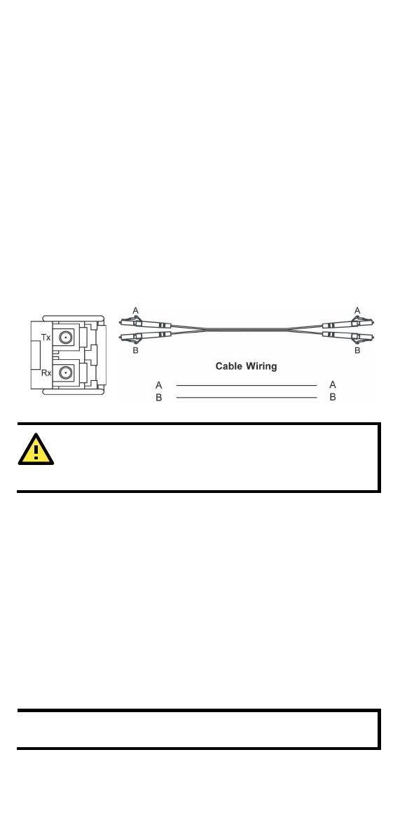
Remember to connect the Tx (transmit) port of device I to the Rx (receive)
port of device II, and the Rx (receive) port of device I to the Tx (transmit)
port of device II. If you make your own cable, we suggest labeling the two
sides of the same line with the same letter (A-to-A and B-to-B, as shown
below, or A1-to-A2 and B1-to-B2).
LC-Port Pinouts
LC-Port to LC-Port Cable Wiring
ATTENTION
This is a Class 1 Laser/LED product. To
avoid causing serious
damage to your eyes, do not stare directly into the Laser Beam.
Reset Button
There are two functions available on the Reset Button. One is to reset the
Ethernet switch to factory default settings by pressing and holding the
Reset button for 5 seconds. Use a pointed object, such as a straightened
paper clip or toothpick, to depress the Reset button. This will cause the
STATE LED to blink once a second. After depressing the button for 5
continuous seconds, the STATE LED will start to blink rapidly. This
indicates that factory default settings have been loaded and you can
release the reset button.
When the ABC-02-USB is connected to the EDS-G500E Ethernet switch,
the reset button allows quick configuration and backs up log files to the
ABC-02-USB. Press the Reset button on top of the EDS-G500E, the
Ethernet switch will start backing up current system configuration files
and event logs to the ABC-02-USB.
NOTE
Do NOT power off the Ethernet switch when loading default
settings.
- 13 -
Turbo Ring DIP Switch Settings
EDS-G500E series are plug-and-play managed redundant Ethernet
switches. The proprietary Turbo Ring protocol was developed by Moxa to
provide better network reliability and faster recovery time. Moxa Turbo
Ring’s recovery time is less than 300 ms (Turbo Ring) or 50 ms (Turbo
Ring V2) compared to a 3- to 5-minute recovery time for commercial
switchesdecreasing the possible loss caused by network failures in an
industrial setting.
There are 4 Hardware DIP Switches for Turbo Ring on the top panel of
EDS-G500E series that can help setup the Turbo Ring easily within
seconds. If you do not want to use a hardware DIP switch to setup the
Turbo Ring, you can use a web browser, telnet, or console to disable this
function.
NOTE
Please refer to the Turbo Ring section in Communication
Redundancy
User's Manual for more detail information about
the setting and usage of Turbo Ring and Turbo Ring V2.
EDS-G500E Series DIP Switches
The default setting for each DIP Switch is OFF. The
following table explains the effect of setting the DIP
Switch to the ON position
.
Turbo RingDIP Switch Settings
DIP 1
DIP 2
DIP 3
DIP 4
Reserved for
future use.
ON: Enable
s this
EDS as the Ring
Master.
ON: Enables the
default “Ring
Coupling” ports.
ON: Activates
DIP switch 2 and
3 to configure
“Turbo Ring”
settings.
OFF: This EDS
will not be the
Ring Master.
OFF: Do not use
this EDS as the
ring coupler.
OFF: DIP switch
1, 2, and
3 will be
disabled.
Turbo Ring V2DIP Switch Settings
DIP 1
DIP 2
DIP 3
DIP 4
ON: Enables the
default “Ring
Coupling
(backup)” port
when DIP switch
3 is already
enabled.
ON: Enables this
EDS as the Ring
Master.
ON: Enables the
default “Ring
Coupling” port.
ON: Activates
DIP switch 1, 2,
and 3 to
configure “Turbo
Ring V2
settings.
OFF: Enables the
default “Ring
Coupling
(primary)” port
when DIP switch
3 is already
enabled.
OFF: This EDS
will not be the
Ring Master.
OFF: Do not use
this EDS as a ring
coupler.
OFF: DIP switch
1, 2, and
3 will be
disabled.
- 14 -
NOTE
You must enable the Turbo Ring function first before using the
DIP switch to activate the Master and Coupler functions.
NOTE
If you do not enable any of the EDS-G500E series switches to be
the Ring Master, the Turbo Ring protocol will automatically
choose the EDS
-G500E series with the smallest MAC address
range to be the Ring Master. If you accidentally enable more than
one
EDS-G500E series to be the Ring Master, these EDS-G500
E
series
switches will auto-
negotiate to determine which one will be
the Ring Master.
LED Indicators
The front panel of the Moxa EDS-G500E series contains several LED
indicators. The function of each LED is described in the following table:
LED
Color
Status
Description
STATE
Green
On
The system passed the self-diagnosis test
on boot-up and is ready to run.
Blinking
1. The switch is under reset progress (1
time/s).
2. Detect ABC-02-USB connect to the
switch (1 time/2s).
Red On
The system failed self-diagnosis on
boot-up.
RAM Test Fail / System Info. Read Fail /
Switch Initial Fail / PTP PHY Error.
(+ Green MSTR lit on : HW FAIL)
FW Checksum Fail / Uncompress Fail.
(+ Green Coupler lit on: SW FAIL)
FAULT
Red On
1. The signal contact is open.
2. ABC Loading/Saving Fail.
3.
The port being disabled because of the
ingress multicast and broadcast
packets exceed the ingress rate limit.
4. Incorrect loop connection in a single
switch.
5. Invalid Ring port connection.
PWR1
Amber
On
Power is being supplied to the main
module’s power input PWR1.
Off
Power is not being supplied to the main
module’s power input PWR1.
PWR2
Amber
On
Power is being supplied to the main
module’s power input PWR2.
Off
Power is not being supplied to the main
module’s power input PWR2.
- 15 -
LED
Color
Status
Description
MSTR/
HEAD
Green
On
1.
The switch is set as the Master of the
Turbo Ring, as the Head of the Turbo
Chain, or as the Root bridge of RSTP.
2. POST H.W. Fail (+Stat on and Fault
blinking).
Blinking
1. The switch has become the Ring Master
of the Turbo Ring.
2.
The Head of the Turbo Chain, after the
Turbo Ring or the Turbo Chain is down.
3. The switch is set as Turbo Chain’s
Member and the corresponding chain
port is down.
Off
1. The switch is not the Master of this
Turbo Ring.
2. This switch is set as a Member of the
Turbo Chain.
CPLR/
TAIL
Green
On
1.
The switch’s coupling function is
enabled to form a back-up path.
2. When it’s set as the Tail of the Turbo
Chain.
3. POST S.W. Fail (+Stat on and Fault
blinking)
Blinking
1. Turbo Chain is down.
2. The switch is set as Turbo Chain’s
Member and the corresponding chain
port is down.
Off
1.
This switch has disabled the coupling
function.
2. This switch is set as a Member of the
Turbo Chain.
FAULT +
MSTR/HEAD
+ CPLR/TAIL
Rotate
Blinking
Sequentially
ABC-02-USB is importing/exporting files.
STATE +
FAULT +
MSTR/HEAD
+ CPLR/TAIL
Blinking
Switch is being discovered/located by
MXview (2 times/s).
10M/
100M
(TP)
Amber
On
TP port’s 10 or 100 Mbps link is active.
Blinking
Data is being transmitted at 10 or 100
Mbps.
Off
TP port’s 10/100 Mbps link is inactive.
1000M
(TP)
Green
On
TP port’s 1000 Mbps link is active.
Blinking
Data is being transmitted at 1000 Mbps.
Off
TP port’s 1000 Mbps link is inactive.
100M
(SFP)
Amber
On
SFP port’s 100 Mbps link is active.
Blinking
Data is being transmitted at 100 Mbps.
Off
SFP port’s 100 Mbps link is inactive.
1000M
(SFP)
Green
On
SFP port’s 1000 Mbps link is active.
Blinking
Data is being transmitted at 1000 Mbps.
Off
SFP port’s 1000 Mbps link is inactive.
- 16 -
Specifications
Technology
Standards IEEE 802.3 for 10BaseT
IEEE 802.3u for 100BaseT(X) and 100BaseFX
IEEE 802.3ab for 1000BaseT(X)
IEEE 802.3z for 1000BaseX
Protocols
IGMPv1/v2/v3, GMRP, GVRP, SNMPv1/v2c/v3,
DHCP Server/Client, DHCP Option 66/67/82, BootP,
TFTP, SNTP, SMTP, RARP, RMON, HTTP, HTTPS,
Telnet, SSH, Syslog, EtherNet/IP, PROFINET,
Modbus/TCP, SNMP Inform, LLDP, IEEE 1588 PTP
V2, IPv6, NTP Server/Client
MIB MIB-II, Ethernet-Like MIB, P-BRIDGE MIB,
Q-BRIDGE MIB, Bridge MIB, RSTP MIB, RMON MIB
Group 1, 2, 3, 9
Flow Control
IEEE 802.3x flow control, back pressure flow control
Interface
RJ45 Ports
8 (EDS-G508E/EDS-G512E-4GSFP) or
12 (EDS-G516E-4GSFP) 10/100/1000BaseT(X)
Fiber Ports
4-port 100/1000BaseSFP slot
(EDS-G512E-4GSFP/EDS-G516-4GSFP only)
USB Ports
USB console port (type B connector)
USB storage port (type A connector)
Button
Reset button
LED Indicators
PWR1, PWR2, FAULT, STATE, 10/100M, 100/1000M,
MSTR/HEAD, CPLR/TAIL
Alarm Contact
1 relay output with current carrying capacity of 1 A
@ 24 VDC
Digital Input 1 input with the same ground, but electrically
isolated from the electronics.
+13 to +30V for state “1”
-30 to +3V for state “0”
Max. input current: 8 mA
Power
Input Voltage
12/24/48/-48 VDC, redundant dual inputs
Input Current
EDS-G516E: 0.46 A @ 24 VDC
EDS-G512E: 0.4 A @ 24 VDC
EDS-G508E: 0.33 A @ 24 VDC
Connection
2 removable 4-contact terminal blocks
Overload Current
Protection
Present
Reverse Polarity
Protection
Present
Physical Characteristics
Housing
Metal, IP30 protection
Dimension
79.2 x 135 x 137 mm (3.1 x 5.3 x 5.4 in)
Installation
DIN-rail mounting, wall mounting (with optional kit)
- 17 -
Environmental Limits
Operating
Temperature
-10 to 60°C (14 to 140°F) for standard models
-40 to 75°C (-40 to 167°F) for -T models
Storage
Temperature
-40 to 85°C (-40 to 185°F)
Ambient Relative
Humidity
5 to 95% (non-condensing)
Altitude
Up to 2000 m
Note: Please contact Moxa if you require products guaranteed to function
properly at higher altitude.
Regulatory Approvals
Safety
UL 508
EMI
FCC Part 15 Subpart B Class A, EN 55022 Class A
EMS EN 61000-4-2 (ESD) Level 4,
EN 61000-4-3 (RS) Level 3,
EN 61000-4-4 (EFT) Level 4,
EN 61000-4-5 (Surge) Level 4,
EN 61000-4-6 (CS) Level 3,
EN 61000-4-8
Shock
IEC 60068-2-27
Free Fall
IEC 60068-2-32
Vibration
IEC 60068-2-6
Warranty
Warranty
5 years
  • Page 1 1
  • Page 2 2
  • Page 3 3
  • Page 4 4
  • Page 5 5
  • Page 6 6
  • Page 7 7
  • Page 8 8
  • Page 9 9
  • Page 10 10
  • Page 11 11
  • Page 12 12
  • Page 13 13
  • Page 14 14
  • Page 15 15
  • Page 16 16
  • Page 17 17

Moxa EDS-G516E Series Quick setup guide

Category
Network switches
Type
Quick setup guide
This manual is also suitable for

Ask a question and I''ll find the answer in the document

Finding information in a document is now easier with AI