
Instruction Manual
Signal Conditioner
SGQ, SGZ
No. SGQZ21JE3 2018.11
Preface
Thank you for purchasing our SGQ (Differential Transmitter) and SGZ (2-Input
Math Function Transmitter).
This manual contains instructions for the mounting, functions, operations and notes
when operating the instruments. To prevent accidents arising from the misuse of
these instruments, please ensure the operator receives this manual.
For detailed usage, please refer to the Instruction Manual for each instrument.
Please download detailed Instruction Manual as well as Communication Instruction
Manual from Shinko website.
http://www.shinko-technos.co.jp/e/ ĺ Products ĺ Signal Conditioners
Notes
• This instrument should be used in accordance with the specifications described in
the manual. If it is not used according to the specifications, it may malfunction or
cause a fire.
• Be sure to follow the warnings, cautions and notices. If they are not observed,
serious injury or malfunction may occur.
• The contents of this instruction manual are subject to change without notice.
• Care has been taken to ensure that the contents of this instruction manual are
correct, but if there are any doubts, mistakes or questions, please inform our sales
department.
• This instrument is designed to be installed on a DIN rail within a control panel. If it is
not, measures must be taken to ensure that the operator cannot touch power
terminals or other high voltage sections.
•
Any unauthorized transfer or copying of this document, in part or in whole, is prohibited.
• Shinko Technos Co., Ltd. is not liable for any damage or secondary damage(s)
incurred as a result of using this product, including any indirect damage.
Safety Precautions
(Be sure to read before using our products)
The safety precautions are classified into categories: “Warning” and “Caution”.
Depending on circumstances, procedures indicated by
Caution may result in
serious consequences, so be sure to follow the directions for usage.
Procedures which may lead to dangerous conditions and
cause death or serious injury, if not carried out properly.
Procedures which may lead to dangerous conditions and
cause superficial to medium injury or physical damage or may
degrade or damage the product, if not carried out properly.
Warning
•
To prevent an electrical shock or fire, only Shinko or other qualified service
personnel may handle the inner assembly.
• To prevent an electrical shock, fire or damage to the instrument, parts replacement
may only be undertaken by Shinko or other qualified service personnel.
Safety Precautions
• To ensure safe and correct use, thoroughly read and understand this
manual before using this instrument.
• This instrument is intended to be used for industrial machinery, machine
tools and measuring equipment. Verify correct usage after purpose-of-use
consultation with our agency or main office. (Never use this instrument for
medical purposes with which human lives are involved.)
• External protection devices must be installed, as malfunction of this
product could result in serious damage to the system or injury to
personnel. Proper periodic maintenance is also required.
• This instrument must be used under the conditions and environment
described in this manual. Shinko Technos Co., Ltd. does not accept liability
for any injury, loss of life or damage occurring due to the instrument being
used under conditions not otherwise stated in this manual.
Caution with Respect to Export Trade Control Ordinance
To avoid this instrument from being used as a component in, or as being
utilized in the manufacture of weapons of mass destruction (i.e. military
applications, military equipment, etc.), please investigate the end users and
the final use of this instrument. In the case of resale, ensure that this
instrument is not illegally exported.
ەInstallation Precautions
Caution
This instrument is intended to be used under the following environmental
conditions (IEC61010-1): Overvoltage category
, Pollution degree 2
Ensure the mounting location corresponds to the following conditions:
• A minimum of dust, and an absence of corrosive gases
• No flammable, explosive gases
• No mechanical vibrations or shocks
• No exposure to direct sunlight, an ambient temperature of -10 to 55
(14 to 131
) that does not change rapidly, and no icing
• An ambient non-condensing humidity of 35 to 85 %RH
• No large capacity electromagnetic switches or cables through which large
current is flowing
• No water, oil, chemicals or the vapors of these substances can come into
direct contact with the unit
•
Please note that the ambient temperature of this unit – not the ambient
temperature of the control panel – must not exceed 55
(131 ) if mounted
through the face of a control panel, otherwise the life of electronic
components (especially electrolytic capacitors) may be shortened.
Note: Avoid setting this instrument directly on or near flammable material
even though the case of this instrument is made of flame-resistant resin.
ەWiring Precautions
Caution
• Do not leave wire remnants in the instrument, because they could cause a
fire or malfunction.
• When wiring, use a crimping pliers and a solderless terminal with an
insulation sleeve in which an M3 screw fits.
• Tighten the terminal screw using the specified torque.
• This instrument does not have a power switch, circuit breaker and fuse.
Therefore, it is necessary to install a power switch, circuit breaker and fuse
externally near the instrument.
(Recommended fuse: Time-lag fuse, rated voltage 250 V AC, rated current 2 A)
• Connect the AC power to the designated terminal as is written in this
instruction manual. Otherwise, it may burn and damage the instrument.
• Do not apply a commercial power source to the sensor which is connected to
the input terminal nor allow the power source to come into contact with the
sensor.
• Use a thermocouple and compensating lead wire according to the sensor
input specifications of this instrument.
• Use the 3-wire RTD according to the sensor input specifications of this
instrument.
• When using direct current or DC voltage input, ensure polarity is correct.
• When wiring, keep Input/Output wires away from AC power sources.
ەOperation and Maintenance Precautions
Caution
• Do not touch live terminals. This may cause an electrical shock or problems
in operation.
• Turn the power supply to the instrument OFF before retightening the terminal
or cleaning. Working on or touching the terminal with the power switched ON
may result in severe injury or death due to electrical shock.
• Use a soft, dry cloth when cleaning the instrument.
(Alcohol based substances may tarnish or deface the unit.)
• As the display section is vulnerable, be careful not to put pressure on,
scratch or strike it with a hard object.
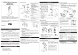
1. Name and Functions
1.1 Front Panel
(Fig. 1.1-1)
ձ Display section Indicates setting contents, input value and output value.
ղ Mounting screw Used for fixing the instrument to the socket or removal from it.
ճ DISP key Switches the displays, and moves to the next setting item.
Releases the lock status of the DISP key by pressing and
holding for 3 seconds.
մ MODE key Selects either a setting mode or a display mode.
Shifts the digit on the Custom display.
Enters the setting mode by pressing and holding for 5
seconds.
յ UP key Increases the numerical value.
Contents of Multi-Display A and B can be changed alternately
when Default Display is RUN display mode 1, 2, 3, 4, 5, 6 and
7.
ն DOWN key
Decreases the numerical value.
Enters Manual mode by pressing and holding for 3 seconds.
շ Output Zero Adjusts the value of Output Zero.
ո Output Span Adjusts the value of Output Span.
Caution
Warning
ᩥࡣ㠃ࢆࡈぴୗࡉ࠸ࠋ
ձ
ղ
ճ
մ
յ
ն
շ
ո
1.2 Display Section
ջ ձ
ղ
ճ
մ
շ
ո
չ
պ
յ
ն
ռ
ս
վ
տ
ր
ց
ւ
(Fig. 1.2-1)
ձ Setting display
indicator A
Lights up in Manual mode.
ղ Input indicator A Lights up when Multi-Display A indicates an input value or
Input math function value.
ճ
Alarm indicator A
Lights up if an input error or input disconnection occurs while
Multi-Display A indicates an input value.
Lights up if an input error or input disconnection occurs in
the following modes:
Custom display modes 1, 2, 3, 4 and 5,
Unlit display mode, Model display mode
մ
Output indicator A
Lights up when Multi-Display A indicates an output value.
յ mA indicato
r
Lights up when mA is selected in [Indication unit].
ն % indicato
r
Lights up in Manual mode, or when % is selected in
[Indication unit].
շ Setting display
indicator B
Lights up while in a setting display.
ո Input indicato
r
B Lights up when Multi-Display B indicates an input value.
չ
Alarm indicator B
Lights up if an input error or input disconnection occurs while
Multi-Display B indicates an input value.
պ
Output indicator B
Lights up when Multi-Display B indicates an output value.
ջ 1 indicator A Lights up in Manual mode, or when Multi-Display A indicates
Input 1 value, output value or input math function value.
ռ 2 indicator A Lights up when Multi-Display A indicates Input 2 value or
input math function value.
ս Multi-Display A Indicates the following in accordance with the display
indication: Input value, output value, custom characters,
setting item
վ
V
indicato
r
Lights up when V is selected in [Indication unit].
տ °C indicato
r
Lights up when °C is selected in [Indication unit].
ր 1 indicato
r
B Lights up when Multi-Display B indicates Input 1 value or
output value.
ց 2 indicato
r
B Lights up when Multi-Display B indicates Input 2 value.
ւ Multi-Display B Indicates the following in accordance with the display
indication: Input value, output value, custom characters,
setting value
Output indicators A and B, Alarm indicators A and B: Red, Other indicators: White
2. Mounting
2.1 Dimensions (Scale: mm)
(Fig. 2.1-1)
8P
socket (SGZ) 11P socket (SGQ)
(Fig. 2.1-2)
2.2 Mounting to, and Removal from the DIN Rail
Mounting to the DIN Rail (Fig. 2.2-1)
ձ Separate the instrument from the socket
by loosening the mounting screw on the
front panel.
ղ Make sure the lock lever of the socket is
located in the lower part of the socket.
Hook the upper side of the socket on the
DIN rail, and fit the lower part of the socket
to the DIN rail. (A clicking sound should be
heard when done properly.)
(Fig. 2.2-1)
Caution
• Before inserting the instrument into the socket, wire the cable. (Refer to “3.
Wiring”.)
• When inserting or removing the socket, make sure the socket is oriented
vertically. If force is applied in any other direction than vertically, a malfunction
may occur.
• If the mountin
g
screw is fastened too ti
g
htl
y
, a malfunction ma
y
occur.
ճ Insert the unit into the socket.
մ Fasten the mounting screw by turning it
clockwise, to secure the unit onto the socket.
Tighten the screw lightly.
Removal from the DIN Rail (Fig. 2.2-2)
ձ Turn the power to the instrument OFF.
ղ Separate the instrument from the socket
by loosening the mounting screw on the
front panel.
ճ Insert a flat blade screwdriver into the lock
lever (lower part of the socket), and remove
the socket from the DIN rail while pulling the
lever down.
(Fig. 2.2-2)
3. Wiring
Lead Wire Solderless Terminal
Use a solderless terminal with an insulation sleeve in which an M3 screw fits
as shown below. The torque should be 0.63 N•m.
Y-type (Scale: mm) Ring-type (Scale: mm)
(Fig. 3-1)
For the terminal arrangement, refer to the Instruction Manual (Detailed
version) or Specification Sheet for each unit.
4. Adjustment
The output of this unit has been already adjusted before shipping. Therefore, it is
not required to adjust the unit in the case users use it with the ordered Input/Output
specification. However, in the case of fine adjustment or calibration between
connected units, adjust the value following the procedure described below.
Connect an mV generator or Dial resistor to the input terminals of this unit.
Connect a digital multimeter to the output terminals.
Adjust Output
(1) Enter the value corresponding to 0% output, then adjust the value with the Output
Zero trimmer while viewing the output value (on the digital multimeter).
(2) Enter the value corresponding to 100% output, then adjust the value with
the
Output Span trimmer while viewing the output value (on the digital multimeter).
(3) Enter the value corresponding to 0% output again, and confirm the output
value (on the digital multimeter).
(4) If the value corresponding to 0% output is not at 0%, repeat steps (1) to (3) again.
Inquiries
For any inquiries about this unit, please contact our agency or the vendor where
you purchased the unit after checking the following.
(e.g.)
• Model ----------------------- SGQ-K01-0-0
• Serial number ------------- 154F05000
In addition to the above, please let us know the details of the malfunction, or
discrepancy, and the operating conditions.
SHINKO TECHNOS CO., LTD.
URL: http://www.shinko-technos.co.jp/e/
2-5-1, Senbahigashi, Minoo, Osaka,
562-0035,
Japan
TEL: +81-72-727-6100 FAX: +81-72-727-7006
Solderless
Terminal
Manufacturer Model
Y-type
Nichifu Terminal Industries Co., Ltd. TMEV1.25Y-3
Japan Solderless Terminal MFG Co., Ltd. VD1.25-B3A
Ring-type
Nichifu Terminal Industries Co., Ltd. TMEV1.25-3
Japan Solderless Terminal MFG Co., Ltd. V1.25-3
DIN rail
DIN rail
Lock lever
DIN rail
DIN rail

ྲྀᢅㄝ᫂᭩ ኚჾ SGQ, SGZ
No. SGQZ21JE1 2018.11
ࡣࡌࡵ
ࡇࡢࡓࡧࡣ㸪ኚჾ SGQ ࡲࡓࡣ SGZ(௨ୗ㸪ᮏჾ)ࢆ࠾㈙࠸ୖࡆ㡬ࡁࡲࡋ࡚㸪ࡲ
ࡇ࠶ࡾࡀ࠺ࡈࡊ࠸ࡲࡋࡓࠋ
ᮏྲྀᢅㄝ᫂᭩(௨ୗ㸪ᮏ᭩)ࡣ㸪ᮏჾࡢタ⨨᪉ἲ㸪ᶵ⬟㸪᧯స᪉ἲ࠾ࡼࡧྲྀᢅ࠸ࡘ
࠸࡚⡆༢ㄝ᫂ࡋࡓࡶࡢ࡛ࡍࠋ
ᮏ᭩ࢆࡼࡃ࠾ㄞࡳ㡬ࡁ㸪༑ศ⌮ゎࡉࢀ࡚ࡽࡈ⏝ࡃࡔࡉ࠸ࡲࡍࡼ࠺࠾㢪࠸⮴ࡋ
ࡲࡍࠋ
ࡲࡓ㸪ㄗࡗࡓྲྀᢅ࠸࡞ࡼࡿᨾ㜵ṆࡢⅭ㸪ᮏ᭩ࡣ᭱⤊ⓗᮏჾࢆ࠾࠸࡞
ࡿ᪉ࡢ࠾ᡭඖ㸪☜ᐇᒆࡅࡽࢀࡿࡼ࠺࠾ྲྀࡾィࡽ࠸ࡃࡔࡉ࠸ࠋ
ヲ⣽࡞⏝᪉ἲࡘ࠸࡚ࡣྛᶵ✀ࡢྲྀᢅㄝ᫂᭩(ヲ⣽∧)ࢆཧ↷ࡋ࡚ࡃࡔࡉ࠸ࠋ
ྛᶵ✀ࡢྲྀᢅㄝ᫂᭩(ヲ⣽∧)ࡣ㸪ୗグᘢ♫ Web ࢧࢺࡼࡾࢲ࣮࢘ࣥࣟࢻࡋ࡚ࡃࡔ
ࡉ࠸ࠋ
http://www.shinko-technos.co.jp ĺ ྲྀࡾᢅ࠸〇ရ ĺ ኚჾ
ࡈὀព
࣭ᮏჾࡣ㸪グ㍕ࡉࢀࡓᵝ⠊ᅖෆ࡛⏝ࡋ࡚ࡃࡔࡉ࠸ࠋ
ᵝ⠊ᅖእ࡛⏝ࡋࡓሙྜ㸪ⅆ⅏㸪ᮏჾࡢᨾ㞀ࡢཎᅉ࡞ࡾࡲࡍࠋ
࣭ᮏ᭩グ㍕ࡉࢀ࡚࠸ࡿ㆙࿌㡯㸪ὀព㡯ࢆᚲࡎᏲࡗ࡚ࡃࡔࡉ࠸ࠋ
ࡇࢀࡽࡢ㆙࿌㡯㸪ὀព㡯ࢆᏲࡽ࡞ࡗࡓሙྜ㸪㔜࡞യᐖࡸᨾࡘ࡞ࡀ
ࡿᜍࢀࡀ࠶ࡾࡲࡍࠋ
࣭ᮏ᭩ࡢグ㍕ෆᐜࡣ㸪ᑗ᮶ண࿌࡞ࡋኚ᭦ࡍࡿࡇࡀ࠶ࡾࡲࡍࠋ
࣭ᮏ᭩ࡢෆᐜ㛵ࡋ࡚ࡣࢆᮇࡋ࡚࠸ࡲࡍࡀ㸪୍ࡈᑂ࡞Ⅼࡸㄗࡾ➼࠾Ẽ࡙
ࡁࡢࡇࡀ࠶ࡾࡲࡋࡓࡽ㸪࠾ᡭᩘ࡛ࡍࡀ࠾㈙࠸ୖࡆ࠸ࡓࡔࡁࡲࡋࡓ㈍ᗑࡲ࡛
ࡈ㐃⤡ࡃࡔࡉ࠸ࠋ
࣭ᮏჾࡣไᚚ┙ෆ DIN ࣮ࣞࣝタ⨨ࡋ࡚⏝ࡍࡿࡇࢆ๓ᥦ〇సࡋ࡚࠸ࡲࡍࠋ
⏝⪅ࡀ㟁※➃Ꮚ➼ࡢ㧗㟁ᅽ㒊㏆࡙࡞࠸ࡼ࠺࡞ฎ⨨ࢆ᭱⤊〇ရഃ࡛⾜ࡗ࡚
ࡃࡔࡉ࠸ࠋ
࣭ᮏ᭩ࡢグ㍕ෆᐜࡢ୍㒊ࡲࡓࡣ㒊ࢆ↓᩿࡛㌿㍕㸪」〇ࡍࡿࡇࡣ⚗Ṇࡉࢀ࡚࠸
ࡲࡍࠋ
࣭ᮏჾࢆ㐠⏝ࡋࡓ⤖ᯝࡢᙳ㡪ࡼࡿᦆᐖ㸪ண ྍ⬟࡞ᮏჾࡢḞ㝗ࡼࡿᦆᐖ㸪
ࡑࡢࡍ࡚ࡢ㛫᥋ⓗᦆᐖࡘ࠸࡚㸪࠸ࡗࡉ࠸㈐௵ࢆ㈇࠸ࡡࡲࡍࡢ࡛ࡈᢎ
ࡃࡔࡉ࠸ࠋ
Ᏻୖࡢࡈὀព(ࡈ⏝๓ᚲࡎ࠾ㄞࡳࡃࡔࡉ࠸ࠋ)
Ᏻୖࡢࡈὀព࡛ࡣ㸪Ᏻὀព㡯ࡢࣛࣥࢡࢆ"㆙࿌㸪ὀព"ࡋ࡚༊ศࡋ࡚࠸ࡲ
ࡍࠋ
࡞࠾㸪
ὀពグ㍕ࡋࡓ㡯࡛ࡶ㸪≧ἣࡼࡗ࡚ࡣ㔜࡞⤖ᯝ⤖ࡧࡘࡃྍ⬟
ᛶࡀ࠶ࡾࡲࡍࡢ࡛㸪グ㍕ࡋ࡚࠸ࡿࡣᚲࡎᏲࡗ࡚ࡃࡔࡉ࠸ࠋ
ྲྀᢅ࠸ࢆㄗࡗࡓሙྜ㸪༴㝤࡞≧ἣࡀ㉳ࡇࡾ࠼࡚㸪ேࡸ㔜
࡞യᐖࢃࡿᨾࡢ㉳ࡇࡿྍ⬟ᛶࡀᐃࡉࢀࡿሙྜࠋ
ྲྀᢅ࠸ࢆㄗࡗࡓሙྜ㸪༴㝤࡞≧ἣࡀ㉳ࡇࡾ࠼࡚㸪୰⛬ᗘࡢ
യᐖࡸ㍍യࢆཷࡅࡿྍ⬟ᛶࡀᐃࡉࢀࡿሙྜ㸪࠾ࡼࡧᶵჾ
ᦆയࡢⓎ⏕ࡀᐃࡉࢀࡿሙྜࠋ
㆙࿌
࣭ឤ㟁࠾ࡼࡧⅆ⅏㜵ṆࡢⅭ㸪㈍ᗑࡢࢧ࣮ࣅࢫ࣐ࣥ௨እࡣᮏჾෆ㒊ゐࢀ࡞
࠸࡛ࡃࡔࡉ࠸ࠋ
࣭ឤ㟁㸪ⅆ⅏ᨾ࠾ࡼࡧᶵჾᨾ㞀㜵ṆࡢⅭ㸪㒊ရࡢࡣ㈍ᗑࡢࢧ࣮ࣅࢫ
࣐ࣥ௨እࡣ⾜ࢃ࡞࠸࡛ࡃࡔࡉ࠸ࠋ
Ᏻ㛵ࡍࡿࡈὀព
࣭ṇࡋࡃᏳ࠾࠸࠸ࡓࡔࡃࡓࡵ㸪ࡈ⏝ࡢ๓ࡣᚲࡎᮏ᭩ࢆࡼࡃ࠾ㄞࡳ
ࡃࡔࡉ࠸ࠋ
࣭ᮏჾࡣ㸪⏘ᴗᶵᲔ࣭ᕤసᶵᲔ࣭ィ ᶵჾ⏝ࡉࢀࡿࢆពᅗࡋ࡚࠸ࡲࡍࠋ
㈍ᗑ⏝┠ⓗࢆࡈᥦ♧ࡢୖ㸪ṇࡋ࠸࠸᪉ࢆࡈ☜ㄆࡃࡔࡉ࠸ࠋ(ே
ࢃࡿ་⒪ᶵჾ➼ࡣ㸪ࡈ⏝࡞ࡽ࡞࠸࡛ࡃࡔࡉ࠸ࠋ)
࣭ᮏჾࡢᨾ㞀ࡸ␗ᖖ࡛ࢩࢫࢸ࣒ࡢ㔜࡞ᨾࢆᘬࡁ㉳ࡇࡍሙྜࡣ㸪ᨾ㜵
Ṇࡢࡓࡵ㸪እ㒊㐺ษ࡞ಖㆤ⨨ࢆタ⨨ࡋ࡚ࡃࡔࡉ࠸ࠋ
ࡲࡓ㸪ᐃᮇⓗ࡞࣓ࣥࢸࢼࣥࢫࢆ㈍ᗑ౫㢗(᭷ൾ)ࡋ࡚ࡃࡔࡉ࠸ࠋ
࣭ᮏ᭩グ㍕ࡢ࡞࠸᮲௳࣭⎔ቃୗ࡛ࡣ⏝ࡋ࡞࠸࡛ࡃࡔࡉ࠸ࠋ
ᮏ᭩グ㍕ࡢ࡞࠸᮲௳࣭⎔ቃୗ࡛⏝ࡉࢀࡓሙྜ㸪≀ⓗ࣭ேⓗᦆᐖࡀⓎ⏕
ࡋ࡚ࡶ㸪ࡑࡢ㈐௵ࢆ㈇࠸ࡡࡲࡍࡢ࡛ࡈᢎࡃࡔࡉ࠸ࠋ
㍺ฟ㈠᫆⟶⌮௧㛵ࡍࡿࡈὀព
㔞◚ቯරჾ(㌷⏝㏵࣭㌷タഛ➼)࡛⏝ࡉࢀࡿࡀ࡞࠸ࡼ࠺㸪᭱⤊⏝㏵
ࡸ᭱⤊ᐈඛࢆㄪᰝࡋ࡚ࡃࡔࡉ࠸ࠋ
ᑦ㸪㈍ࡘ࠸࡚ࡶṇ㍺ฟࡉࢀ࡞࠸ࡼ࠺㸪༑ศὀពࡋ࡚ࡃࡔࡉ࠸ࠋ
ەྲྀࡾࡅୖࡢὀព
ὀ ព
[ᮏჾࡣ㸪ḟࡢ⎔ቃᵝ࡛⏝ࡉࢀࡿࡇࢆពᅗࡋ࡚࠸ࡲࡍࠋ(IEC61010-1)]
࣭㐣㟁ᅽ࢝ࢸࢦࣜ
㸪ởᰁᗘ2
[ᮏჾࡣ㸪ୗグࡢࡼ࠺࡞ሙᡤ࡛ࡈ⏝ࡃࡔࡉ࠸ࠋ]
࣭ሻᇕࡀᑡ࡞ࡃ㸪⭉⼃ᛶ࢞ࢫࡢ࡞࠸ࡇࢁࠋ
࣭ྍ⇞ᛶ㸪⇿Ⓨᛶ࢞ࢫࡢ࡞࠸ࡇࢁࠋ
࣭ᶵᲔⓗືࡸ⾪ᧁࡢᑡ࡞࠸ࡇࢁࠋ
࣭┤ᑕ᪥ගࡀ࠶ࡓࡽࡎ㸪࿘ᅖ ᗘࡀ-10㹼55
࡛ᛴ⃭࡞ ᗘኚ࠾ࡼࡧị⤖
ࡢྍ⬟ᛶࡀ࡞࠸ࡇࢁࠋ
࣭‵ᗘࡀ35㹼85 %RH࡛㸪⤖㟢ࡢྍ⬟ᛶࡀ࡞࠸ࡇࢁࠋ
࣭ᐜ㔞ࡢ㟁☢㛤㛢ჾࡸ㸪㟁ὶࡢὶࢀ࡚࠸ࡿ㟁⥺ࡽ㞳ࢀ࡚࠸ࡿࡇࢁࠋ
࣭Ỉ㸪Ἔ࠾ࡼࡧ⸆ရࡲࡓࡣࡑࢀࡽࡢẼࡀ┤᥋࠶ࡓࡿᜍࢀࡢ࡞࠸ࡇࢁࠋ
࣭ไᚚ┙ෆタ⨨ࡍࡿሙྜ㸪ไᚚ┙ࡢ࿘ᅖ ᗘ࡛ࡣ࡞ࡃ㸪ᮏჾࡢ࿘ᅖ ᗘࡀ
55
ࢆ㉸࠼࡞࠸ࡼ࠺ࡋ࡚ࡃࡔࡉ࠸ࠋ
ᮏჾࡢ㟁Ꮚ㒊ရ(≉㟁ゎࢥࣥࢹࣥࢧ)ࡢᑑࢆ⦰ࡵࡿᜍࢀࡀ࠶ࡾࡲࡍࠋ
ͤཧ ⪃: ᮏჾࡢࢣ࣮ࢫᮦ㉁ࡣ㸪㞴⇞ᛶᶞ⬡ࢆ⏝ࡋ࡚࠸ࡲࡍࡀ㸪⇞࠼ࡸࡍ࠸
ࡶࡢࡢࡑࡤࡣタ⨨ࡋ࡞࠸࡛ࡃࡔࡉ࠸ࠋ
ࡲࡓ㸪⇞࠼ࡸࡍ࠸≀ࡢୖ┤᥋⨨ࡃࡇࡣࡋ࡞࠸࡛ࡃࡔࡉ࠸ࠋ
ە㓄⥺ୖࡢὀព
ὀ ព
࣭㓄⥺సᴗࢆ⾜࠺ሙྜ㸪㟁⥺ᒌࢆᮏჾࡢ㏻㢼❆ⴠࡋ㎸ࡲ࡞࠸࡛ࡃࡔࡉ࠸ࠋ
ⅆ⅏㸪ᨾ㞀㸪ㄗືసࡢཎᅉ࡞ࡾࡲࡍࠋ
࣭ᮏჾࡢ➃Ꮚ㓄⥺సᴗࢆ⾜࠺ሙྜ㸪M3ࡡࡌ㐺ྜࡍࡿ⤯⦕ࢫ࣮ࣜࣈᅽ╔
➃Ꮚ࠾ࡼࡧᅽ╔ᕤලࢆ⏝ࡋ࡚ࡃࡔࡉ࠸ࠋ
࣭➃Ꮚࡡࡌࢆ⥾ࡵࡅࡿሙྜ㸪㐺ṇ⥾ࡵࡅࢺࣝࢡ௨ෆ࡛⥾ࡵࡅ࡚ࡃࡔࡉ
࠸ࠋ
࣭ᮏჾࡣ㟁※ࢫࢵࢳ㸪㐽᩿ჾ࠾ࡼࡧࣄ࣮ࣗࢬࢆෆⶶࡋ࡚࠸ࡲࡏࢇࠋ
ᚲࡎᮏჾࡢ㏆ࡃ㟁※ࢫࢵࢳ㸪㐽᩿ჾ࠾ࡼࡧࣄ࣮ࣗࢬࢆู㏵タࡅ࡚ࡃࡔ
ࡉ࠸ࠋ
(᥎ዡࣄ࣮ࣗࢬ: ᐃ᱁㟁ᅽ250 V AC㸪ᐃ᱁㟁ὶ: 2 Aࡢࢱ࣒ࣛࢢࣄ࣮ࣗࢬ)
࣭AC㟁※ࡢ㓄⥺ࡣ㸪ᮏ᭩グ㍕ࡋ࡚࠸ࡿ㏻ࡾ㸪ᑓ⏝ࡢ➃Ꮚ㓄⥺ࡋ࡚ࡃࡔࡉ
࠸ࠋ
AC㟁※ࢆࡢ➃Ꮚ㓄⥺ࡍࡿ㸪ᮏჾࢆ↝ᦆࡋࡲࡍࠋ
࣭ධຊ➃Ꮚ᥋⥆ࡉࢀࡿࢭࣥࢧ㸪ၟ⏝㟁※ࡀ᥋ゐࡲࡓࡣ༳ຍࡉࢀ࡞࠸ࡼ࠺
ࡋ࡚ࡃࡔࡉ࠸ࠋ
࣭⇕㟁ᑐ㸪⿵ൾᑟ⥺ࡣᮏჾࡢࢭࣥࢧධຊᵝྜࡗࡓࡶࡢࢆࡈ⏝ࡃࡔࡉ࠸ࠋ
࣭ ᢠయࡣ3ᑟ⥺ᘧࡢࡶࡢ࡛㸪ᮏჾࡢࢭࣥࢧධຊᵝྜࡗࡓࡶࡢࢆࡈ
⏝ࡃࡔࡉ࠸ࠋ
࣭┤ὶ㟁ᅽ㸪㟁ὶධຊࢆ⏝ࡍࡿሙྜ㸪ᴟᛶࢆ㛫㐪ࢃ࡞࠸ࡼ࠺㓄⥺ࡋ࡚ࡃࡔ
ࡉ࠸ࠋ
࣭ධฟຊ⥺㟁※⥺ࡣ㞳ࡋ࡚㓄⥺ࡋ࡚ࡃࡔࡉ࠸ࠋ
ە㐠㌿㸪ಖᏲࡢὀព
ὀ ព
࣭ឤ㟁㜵Ṇ࠾ࡼࡧᶵჾᨾ㞀㜵ṆࡢⅭ㸪㏻㟁୰ࡣ➃Ꮚゐࢀ࡞࠸࡛ࡃࡔࡉ࠸ࠋ
࣭➃Ꮚࡢቑ⥾ࡵ࠾ࡼࡧΎᤲ➼ࡢసᴗࢆ⾜࠺ࡣ㸪ᮏჾࡢ㟁※ࢆษࡗࡓ≧ែ࡛
⾜ࡗ࡚ࡃࡔࡉ࠸ࠋ
㟁※ࢆධࢀࡓ≧ែ࡛సᴗࢆ⾜࠺㸪ឤ㟁ࡢⅭ㸪ேࡸ㔜࡞യᐖࢃ
ࡿᨾࡢ㉳ࡇࡿྍ⬟ᛶࡀ࠶ࡾࡲࡍࠋ
࣭ᮏჾࡢởࢀࡣ㸪ᰂࡽ࠸ᕸ㢮࡛ᣔࡁࡋ࡚ࡃࡔࡉ࠸ࠋ
(ࢩࣥࢼ㢮ࢆ⏝ࡋࡓሙྜ㸪ᮏჾࡢኚᙧ㸪ኚⰍࡢᜍࢀࡀ࠶ࡾࡲࡍ)
࣭⾲♧㒊ࡣയࡘࡁࡸࡍ࠸ࡢ࡛㸪◳࠸≀࡛᧿ࡗࡓࡾ㸪྇࠸ࡓࡾ࡞ࡣࡋ࡞࠸࡛
ࡃࡔࡉ࠸ࠋ
1. ྛ㒊ࡢྡ⛠ࡣࡓࡽࡁ
1.1 ๓㠃
(ᅗ 1.1-1)
ձ ⾲♧㒊 タᐃෆᐜࡸධຊ್㸪ฟຊ㔞ࢆ⾲♧ࡋࡲࡍࠋ
ղ ྲྀࡡࡌ ᮏჾࢆࢯࢣࢵࢺᅛᐃࡍࡿሙྜ㸪ࡲࡓࡣࢯࢣࢵࢺࡽእࡍሙ
ྜ⏝ࡋࡲࡍࠋ
ճ DISP࣮࢟ ⏬㠃⾲♧ࡢษࡾ᭰࠼㸪タᐃ㡯┠ࢆ⛣⾜ࡋࡲࡍࠋ
3⛊㛫ᢲࡋ⥆ࡅࡿ㸪DISP࣮࢟ࡢࣟࢵࢡゎ㝖ࢆ⾜࠸ࡲࡍࠋ
մ MODE࣮࢟ ࣮ࣔࢻ(タᐃ࣮ࣔࢻ⾲♧࣮ࣔࢻ)ࡢ㑅ᢥࢆ⾜࠸ࡲࡍࠋ
࢝ࢫࢱ࣒⏬㠃࡛ࡣ᱆⛣ືࢆ⾜࠸ࡲࡍࠋ
5⛊㛫ᢲࡋ⥆ࡅࡿ㸪タᐃ࣮ࣔࢻ⛣⾜ࡋࡲࡍࠋ
յ ࢵࣉ࣮࢟ ᩘ್ࢆቑຍࡉࡏࡲࡍࠋ
ࢹࣇ࢛ࣝࢺ⏬㠃ࡀ㐠㌿⏬㠃࣮ࣔࢻ1㸪㐠㌿⏬㠃࣮ࣔࢻ2㸪㐠 ㌿
⏬㠃࣮ࣔࢻ3㸪㐠㌿⏬㠃࣮ࣔࢻ4㸪㐠㌿⏬㠃࣮ࣔࢻ5㸪㐠㌿⏬
㠃࣮ࣔࢻ6㸪㐠㌿⏬㠃࣮ࣔࢻ7ࡢሙྜ㸪࣐ࣝࢳ⾲♧ჾA㸪࣐ࣝ
ࢳ⾲♧ჾBࡢ⾲♧ෆᐜࢆධࢀ᭰࠼ࡲࡍࠋ
ն ࢲ࣮࢘ࣥ࢟ ᩘ್ࢆῶᑡࡉࡏࡲࡍࠋ
3⛊㛫ᢲࡋ⥆ࡅࡿ㸪࣐ࢽ࣮ࣗࣝࣔࢻ⛣⾜ࡋࡲࡍࠋ
շ ฟຊࢮࣟㄪᩚ1 ฟຊࡢࢮࣟഃࡢฟຊ㔞ࢆㄪᩚࡋࡲࡍࠋ
ո ฟຊࢫࣃࣥㄪᩚ1 ฟຊࡢࢫࣃࣥഃࡢฟຊ㔞ࢆㄪᩚࡋࡲࡍࠋ
ὀព
㆙࿌
For the English manual, see the reverse.
ձ
ղ
ճ
մ
յ
ն
շ
ո
1.2 ⾲♧㒊
ջ ձ
ղ
ճ
մ
շ
ո
չ
պ
յ
ն
ռ
ս
վ
տ
ր
ց
ւ
(ᅗ1.2-1)
ձ タᐃ⏬㠃⾲♧ⅉA ࣐ࢽ࣮ࣗࣝࣔࢻⅬⅉࡋࡲࡍࠋ
ղ ධຊ⾲♧ⅉA ࣐ࣝࢳ⾲♧ჾAࡀධຊ್⾲♧ࡲࡓࡣධຊ₇⟬್⾲♧Ⅼⅉ
ࡋࡲࡍࠋ
ճ ࣮࣒ࣛ⾲♧ⅉA ࣐ࣝࢳ⾲♧ჾAࡀධຊ್⾲♧࡛ධຊ␗ᖖࡲࡓࡣධຊ᩿⥺Ⅼ
ⅉࡋࡲࡍࠋ࢝ࢫࢱ࣒⏬㠃⾲♧࣮ࣔࢻ1㸪࢝ࢫࢱ࣒⏬㠃⾲♧ࣔ
࣮ࢻ2㸪࢝ࢫࢱ࣒⏬㠃⾲♧࣮ࣔࢻ3㸪࢝ࢫࢱ࣒⏬㠃⾲♧࣮ࣔࢻ
4㸪࢝ࢫࢱ࣒⏬㠃⾲♧࣮ࣔࢻ5㸪ᾘⅉ⾲♧࣮ࣔࢻࡲࡓࡣᙧྡ⾲
♧࣮ࣔࢻ࡛ධຊ␗ᖖࡲࡓࡣධຊ᩿⥺ࡶⅬⅉࡋࡲࡍࠋ
մ ฟຊ⾲♧ⅉA ࣐ࣝࢳ⾲♧ჾAࡀฟຊ㔞⾲♧Ⅼⅉࡋࡲࡍࠋ
յ mA༢⾲♧ⅉ ༢⾲♧㑅ᢥ࡛mAࢆ㑅ᢥࡋࡓሙྜⅬⅉࡋࡲࡍࠋ
ն %༢⾲♧ⅉ ༢⾲♧㑅ᢥ࡛%ࢆ㑅ᢥࡋࡓሙྜࡲࡓࡣ࣐ࢽ࣮ࣗࣝࣔࢻ
Ⅼⅉࡋࡲࡍࠋ
շ タᐃ⏬㠃⾲♧ⅉB タᐃ⏬㠃Ⅼⅉࡋࡲࡍࠋ
ո ධຊ⾲♧ⅉB ࣐ࣝࢳ⾲♧ჾBࡀධຊ್⾲♧Ⅼⅉࡋࡲࡍࠋ
չ ࣮࣒ࣛ⾲♧ⅉB ࣐ࣝࢳ⾲♧ჾBࡀධຊ್⾲♧࡛ධຊ␗ᖖࡲࡓࡣධຊ᩿⥺Ⅼ
ⅉࡋࡲࡍࠋ
պ ฟຊ⾲♧ⅉB ࣐ࣝࢳ⾲♧ჾBࡀฟຊ㔞⾲♧Ⅼⅉࡋࡲࡍࠋ
ջ 1⾲♧ⅉA ࣐ࣝࢳ⾲♧ჾAࡀධຊ1⾲♧㸪ฟຊ㔞⾲♧㸪࣐ࢽࣗࣝࣔ
࣮ࢻࡲࡓࡣධຊ₇⟬್⾲♧Ⅼⅉࡋࡲࡍࠋ
ռ 2⾲♧ⅉA ࣐ࣝࢳ⾲♧ჾAࡀධຊ2⾲♧ࡲࡓࡣධຊ₇⟬್⾲♧Ⅼⅉ
ࡋࡲࡍࠋ
ս ࣐ࣝࢳ⾲♧ჾA ⏬㠃⾲♧ᛂࡌࡓෆᐜ(ධຊ್㸪ฟຊ㔞㸪࢝ࢫࢱ࣒⾲♧㸪タ
ᐃ㡯┠⾲♧)ࢆ⾲♧ࡋࡲࡍࠋ
վ V༢⾲♧ⅉ ༢⾲♧㑅ᢥ࡛Vࢆ㑅ᢥࡋࡓሙྜⅬⅉࡋࡲࡍࠋ
տ °C༢⾲♧ⅉ ༢⾲♧㑅ᢥ࡛°Cࢆ㑅ᢥࡋࡓሙྜⅬⅉࡋࡲࡍࠋ
ր 1⾲♧ⅉB ࣐ࣝࢳ⾲♧ჾBࡀධຊ1⾲♧ࡲࡓࡣฟຊ㔞⾲♧Ⅼⅉࡋࡲ
ࡍࠋ
ց 2⾲♧ⅉB ࣐ࣝࢳ⾲♧ჾBࡀධຊ2⾲♧Ⅼⅉࡋࡲࡍࠋ
ւ ࣐ࣝࢳ⾲♧ჾB ⏬㠃⾲♧ᛂࡌࡓෆᐜ(ධຊ್㸪ฟຊ㔞㸪࢝ࢫࢱ࣒⾲♧㸪タ
ᐃ್⾲♧)ࢆ⾲♧ࡋࡲࡍࠋ
ͤฟຊ⾲♧ⅉ A㸪B ࠾ࡼࡧ࣮࣒ࣛ⾲♧ⅉ A㸪B ࡣ㉥Ⰽࠋࡢ⾲♧ⅉࡣⓑⰍࠋ
2. ྲྀࡾࡅ
2.1 እᙧᑍἲᅗ(༢: mm)
(ᅗ 2.1-1)
8P ࢯࢣࢵࢺ(SGZ) 11P ࢯࢣࢵࢺ(SGQ)
(ᅗ 2.1-2)
2.2 DIN ࣮ࣞࣝࡢྲྀࡾࡅ㸪ྲྀࡾእࡋ
DIN ࣮ࣞࣝࡢྲྀࡾࡅ
ձᮏჾ๓㠃ࡢྲྀࡡࡌࢆ⦆ࡵ࡚㸪ᮏჾࢆࢯࢣࢵࢺ
ࡽእࡋ࡚ࡃࡔࡉ࠸ࠋ
ղࢯࢣࢵࢺࡣ㸪ࣟࢵࢡࣞࣂ࣮ࡀ࠶ࡿ᪉ࢆୗࡋ࡚
ࡃࡔࡉ࠸ࠋࢯࢣࢵࢺࡢୖ㒊ࢆ DIN ࣮ࣞࣝᘬࡗ
ࡅ㸪ୗ㒊ࢆᢲࡋ࡚ࡃࡔࡉ࠸ࠋ
(࢝ࢳࢵ㡢ࡀࡋࡲࡍ)(ᅗ 2.2-1)
(ᅗ 2.2-1)
ὀ ព
࣭ᮏჾࢆࢯࢣࢵࢺᤄࡋ㎸ࡴ๓㸪[3. 㓄 ⥺]ࢆཧ↷ࡋ࡚㓄⥺ࢆ⾜ࡗ࡚ࡃࡔࡉ࠸ࠋ
࣭ࢯࢣࢵࢺ╔⬺ࡣ㸪ࢯࢣࢵࢺࡢ㠃ᑐࡋ࡚ᆶ┤ᢤࡁᕪࡋࡋ࡚ࡃࡔࡉ࠸ࠋ
ᆶ┤᪉ྥ௨እࡢຊࡀຍࢃࡿ㸪ᨾ㞀ࡢཎᅉ࡞ࡿሙྜࡀ࠶ࡾࡲࡍࠋ
࣭ྲྀࡡࡌࡣᙉࡃ⥾ࡵࡅ㐣ࡂࡿ㸪ᨾ㞀ࡢཎᅉ࡞ࡿሙྜࡀ࠶ࡾࡲࡍࠋ
ճᮏჾࢆࢯࢣࢵࢺᤄࡋ㎸ࢇ࡛ࡃࡔࡉ࠸ࠋ
մྲྀࡡࡌࢆィ᪉ྥᅇࡋ࡚㸪ࢯࢣࢵࢺࡽᮏჾ
ࡀᢤࡅ࡞࠸⛬ᗘ㍍ࡃ⥾ࡵ࡚ࡃࡔࡉ࠸ࠋ
DIN ࣮ࣞࣝࡽࡢྲྀࡾእࡋ
ձᮏჾࡢ౪⤥㟁※ࢆษࡗ࡚ࡃࡔࡉ࠸ࠋ
ղᮏჾ๓㠃ࡢྲྀࡡࡌࢆ⦆ࡵ࡚㸪ᮏჾࢆࢯࢣࢵࢺ
ࡽእࡋ࡚ࡃࡔࡉ࠸ࠋ
ճࢯࢣࢵࢺୗ㒊ࡢࣟࢵࢡࣞࣂ࣮࣐ࢼࢫࢻࣛ
ࣂ࣮ࢆᕪ㎸ࡳ㸪ࣟࢵࢡࣞࣂ࣮ࢆୗࡆ࡞ࡀࡽDIN
࣮ࣞࣝࡽእࡋ࡚ࡃࡔࡉ࠸ࠋ(ᅗ2.2-2)
(ᅗ2.2-2)
3. 㓄 ⥺
࣮ࣜࢻ⥺ᅽ╔➃Ꮚࡘ࠸࡚
ୗグࡢࡼ࠺࡞㸪M3 ࡢࡡࡌ㐺ྜࡍࡿ⤯⦕ࢫ࣮ࣜࣈᅽ╔➃Ꮚࢆ⏝ࡋ࡚ࡃࡔࡉ࠸ࠋ
⥾ࢺࣝࢡࡣ 0.63 N㺃m ࢆᣦᐃࡋ࡚ࡃࡔࡉ࠸ࠋ
Y ᙧᅽ╔➃Ꮚእᙧᅗ(༢: mm) ᙧᅽ╔➃Ꮚእᙧᅗ(༢: mm)
(ᅗ 3-1)
➃Ꮚ㓄ิࡣ㸪ྛᶵ✀ࡢྲྀᢅㄝ᫂᭩(ヲ⣽∧)ࡲࡓࡣᵝ᭩ࢆࡈཧ↷ࡃࡔࡉ࠸ࠋ
4. ㄪ ᩚ
ᮏჾࡣ㸪ᕤሙฟⲴฟຊㄪᩚ῭ࡳ࡛ࡍࠋ
ࡈὀᩥ࠸ࡓࡔ࠸ࡓධฟຊᵝ㏻ࡾࡈ⏝࡞ࡿሙྜ㸪ㄪᩚࡢᚲせࡣ࠶ࡾࡲࡏࢇࠋ
ࡓࡔࡋ㸪᥋⥆ᶵჾࡢᚤㄪᩚࢆࡍࡿሙྜࡸᰯṇ㸪௨ୗࡢᡭ㡰࡛ㄪᩚࡋ࡚ࡃࡔࡉ࠸ࠋ
ᮏჾࡢධຊ➃ᏊmVⓎ⏕ჾࡲࡓࡣࢲࣖࣝᢠჾࢆ᥋⥆ࡋ࡚ࡃࡔࡉ࠸ࠋ
ฟຊ➃Ꮚࢹࢪࢱ࣐ࣝࣝࢳ࣓࣮ࢱࢆ᥋⥆ࡋ࡚ࡃࡔࡉ࠸ࠋ
ฟຊࢆㄪᩚࡍࡿ
ձฟຊ0%್ࢆධຊࡋ㸪ฟຊ್(ࢹࢪࢱ࣐ࣝࣝࢳ࣓࣮ࢱࡢᣦ♧)ࢆぢ࡞ࡀࡽฟຊ
ࢮࣟㄪᩚ⏝࣮࣒࣎ࣜࣗࢆᅇࡋ࡚ㄪᩚࡋ࡚ࡃࡔࡉ࠸ࠋ
ղฟຊ100%್ࢆධຊࡋ㸪ฟຊ್(ࢹࢪࢱ࣐ࣝࣝࢳ࣓࣮ࢱࡢᣦ♧)ࢆぢ࡞ࡀࡽฟຊ
ࢫࣃࣥㄪᩚ⏝࣮࣒࣎ࣜࣗࢆᅇࡋ࡚ㄪᩚࡋ࡚ࡃࡔࡉ࠸ࠋ
ճᗘ㸪ฟຊ0%್ࢆධຊࡋ㸪ฟຊ್(ࢹࢪࢱ࣐ࣝࣝࢳ࣓࣮ࢱࡢᣦ♧)ࢆ☜ㄆࡋ࡚
ࡃࡔࡉ࠸ࠋ
մฟຊ0%್ࡀࡎࢀ࡚࠸ࡿሙྜ㸪ձ㹼ճࢆ⧞ࡾ㏉ࡋ⾜ࡗ࡚ࡃࡔࡉ࠸ࠋ
࠾ၥ࠸ྜࢃࡏ
ᮏჾࡘ࠸࡚᫂࡞Ⅼࡀࡈࡊ࠸ࡲࡋࡓࡽ㸪ኚ࠾ᡭᩘ࡛ࡍࡀᮏჾࡢୗグ㡯┠ࢆࡈ☜
ㄆࡢୖ㸪࠾㈙࠸ୖࡆ࠸ࡓࡔࡁࡲࡋࡓ㈍ᗑ࠾ၥ࠸ྜࢃࡏࡃࡔࡉ࠸ࠋ
()
࣭ᙧ ྡ SGQ-K01-0-0
࣭ィჾ␒ྕ 154F05000
࡞࠾㸪ືసୖࡢලྜࡘ࠸࡚ࡣ㸪ࡑࡢෆᐜࡈ⏝≧ែࡢヲ⣽ࢆලయⓗ࠾▱ࡽ
ࡏࡃࡔࡉ࠸ࠋ
ᅽ╔➃Ꮚ ࣓࣮࢝ ᙧ ྡ
Y ᙧ
ࢽࢳࣇ➃Ꮚ TMEV1.25Y-3
᪥ᮏᅽ╔➃Ꮚ VD1.25-B3A
ᙧ
ࢽࢳࣇ➃Ꮚ TMEV1.25-3
᪥ᮏᅽ╔➃Ꮚ V1.25-3
ᮏ♫ ࠛ 㜰ᗓ⟪㠃ᕷ⯪ሙᮾ ┠ ␒ ྕ
7(/)$;
85/KWWSZZZVKLQNRWHFKQRVFRMS(PDLOVDOHV#VKLQNRWHFKRVFRMS
㜰Ⴀᴗᡤ 7
7(/)$;
ᮾிႠᴗᡤ ࠛ ᮾி㒔୰ኸ༊᪂ᕝ ┠ ␒ ྕ
7(/)$;
ྡྂᒇႠᴗᡤ ࠛ ឡ▱┴ྡྂᒇᕷᮾ༊ᮾእᇼ⏫ ␒
&6 ᮾእᇼࣅࣝ ྕᐊ
7(/)$;
⚄ዉᕝ7(/ 㝣7(/
ᗈᓥ7(/ ⚟ᒸ7(/
-
 1
1
-
 2
2


Shinko SGQ User manual
- Type
- User manual
Ask a question and I''ll find the answer in the document
Finding information in a document is now easier with AI
Related papers
Other documents
-
Vaisala GMP343 User manual
-
Epson ColorWorks C3500 Owner's manual
-
Lifetime 90274 Owner's manual
-
 AND AX-ST-CH-A1 User manual
-
AND AX-HA-CHG User manual
-
GE Baker Hughes PV 212 User manual
-
Fujitsu ScanSnap SV600 User manual
-
WD WD AV User manual
-
MUTOH XpertJet XPJ-1641SR Startup Manual
-
Porsche 971044033 Installation Instructions Manual
