Page is loading ...

Installation, operating and
maintenance instructions
High performance solar collector
CFK-1
Roof top installation with
AluPlus installation system
Single-row roof integration
Wolf GmbH, Postfach 1380, D-84048 Mainburg, Tel. +498751/74-0, Fax +498751/741600, Internet: www.wolf-heiztechnik.de
3062815_201508 Subjecttotechnicalmodications
GB
P 9

2
3062815_201508
Contents
Contents Standards and regulations . . . . . . . . . . . . . . . . . . . . . . . . . . . . . . . . . . . . . . .4
Safety instructions /
Protection against lightning ......................................5
Snow and wind loads . . . . . . . . . . . . . . . . . . . . . . . . . . . . . . . . . . . . . . . . . . .6
Information on system hydraulics..................................7
Information regarding the system hydraulics .........................8
General preparations ...........................................9
Rooftop installation - General....................................11
Rooftop installation -
Interlocking tiles, plain tiles......................................13
Rooftop installation - Slate tiles ..................................15
Rooftop installation - Corrugated roof..............................16
Roof integration - Interlocking tile.................................18
Roof integration - Slate roof .....................................24
Roof integration - Mönch-Nonne .................................31
Fitting the sensors ............................................37
Filling the system / Safety datasheet / Initial start-up ..................38
Pressure testing / Venting the system .............................39
System operating pressure......................................40
Commissioning check list .......................................41
Operation / Inspection and service................................42
Inspection and service checklist..................................44
Faults - Causes - Remedies.....................................47
Product fiche according to Regulation (EU) no. 811-812/2013 ..........48
Notes ......................................................50
Declaration of Conformity.......................................52
Additional installation instructions are available for the following assembly
systems:
- Alu-Flex-Uinstallationframeforat-roofandwallmounting
- Roof integration set 2-row, or 3-row for interlocking tiles
Note:

3
3062815_201508
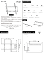
Specication
Collector CFK-1
Casing Deep-drawn aluminium tray, natural,
sea-water resistant.
Dimensions (L x W x H) / (external edge) 2099 x 1099 x 110 mm
Gross surface area
2.3 m²
Effective absorber area 2.0 m²
Weight (dry) 36 kg
Content 1.1 litres
Absorber:
aluminium:copper
Style: Harp, highly selective coating
Cover 3.0 mm solar safety glass, hail-proof *
Thermal insulation Mineral wool
Connections Flat-packing with union nut G ¾"
Angle of inclination 15° to 90°
Opticalefciency* 76.7%
Heatlosscoefcienta
1
* 3.669 W/(m K²)
Heatlosscoefcienta
2
* 0.018 W/(m² K²)
Stagnation temperature *
(permiss. operating temp.)
196 °C
Irradiation angle correction factor IAM-50 * 95%
Thermal capacity C * 7.78 kJ/(m² K)
Max. operating pressure 10 bar
Heat transfer medium ANRO ready-mixed (45% by vol.)
Recommended throughput 90 l / (h x number of collectors)
Solar keymark register number 011-7S591F
* values to EN 12975

4
3062815_201508
Standards and regulations
Observe the locally applicable regulations, rules and guidelines during
assembly, installation and operation.
The following standards and regulations must also be observed:
Installation on roofs
Observe all current Health & Safety regulations
- EN 1991 (+NA) Effects on load-bearing structures
In particular Parts 1-3: Snow loads
Parts 1-4: Wind loads
Connection of solar heating systems
- EN 12976 Solar heating systems and their components
Prefabricated systems (this includes generally applicable
information regarding design and implementation)
- EN 12977 Solar heating systems and their components
Bespoke systems (this includes generally applicable
information regarding design and implementation)
- VDI 6002 Solar heating for domestic water
Electrical connection
- VDE 0100 Erection of power installations with rated voltages
below 1000 V
- VDE 0105 Cables and lines in buildings
- EN 62305 Parts 1-4 Protection against lightning
- VDE 0100 Part 540 Selection and erection of electrical equipment
- earthing arrangements, protective conductors,
equipotential bonding conductors
The collectors are tested in accordance with the following standards:
EN 12975-1 Quality control for solar heating collectors
EN 12975-2 Performance test for solar heating collectors
Standards and
regulations

5
3062815_201508
Safety instructions /
Protection against lightning
The following symbols are used in conjunction with these important instructions
concerning personal safety, as well as operational reliability.
"Safety instructions" are instructions that must be observed exactly,
to prevent injury and material losses,
e.g. The potentially very high temperatures inside the collector result
in a risk of scalding from the hot heat transfer medium.
"CAUTION" indicates technical instructions that you must observe
to prevent material losses and equipment malfunctions.
The connection of the collector array to an existing or new lightning protection
system and the installation of equipotential bonding may only be carried out
by an authorised contractor, under consideration of local conditions and in
compliance with the following technical rules:
EN 62305 Parts 1-4 Protection against lightning
VDE 0100 Part 540 Selection and erection of electrical equipment
- earthing arrangements, protective conductors,
equipotential bonding conductors
Alignment and shading
Ideally, the collectors should be oriented between south-east and south-west
(optimum: south). Please refer to our technical advisers in case of an alternative
orientation. Trees, neighbouring structures, chimneys, etc. should throw as
little shade over the collectors as possible. Observe the different position of
the sun (summer/winter).
The distance between the upper end of the solar collector and the lower edge
of the ridge should be at least 3 roof tiles, in order to reduce wind forces and
toallowsufcientspaceforinstallation.
Safety instructions
CAUTION
Protection against lightning
Notes on installation position

6
3062815_201508
Snow and wind loads
The load on the collector array is a combination of wind and snow loads which
are determined by the dimensions of the building, the roof shape and the
location. A precise calculation of the assumed loads must be carried out for
eachspecicinstallation,inlinewithEN1990(+NA)andEN1991(+NA)and
under consideration of regional regulations.
CFK-1 collectors may be used for pressure and suction loads of up to
2.4 kN/m². By using the snow load extension set, the maximum permissible
pressure load may be increased to 4 kN/m².
For safety reasons, the cross battens, rafters and roof tiles under the roof
hooks must not show signs of previous damage (cracking, drill holes, ageing),
else they will not withstand the loads to which they are subjected. If in doubt,
replace the battens and roof tiles in those sections.
We recommend the use of metal tiles below the roof hooks, particularly in
areas of high snowfall.
To avoid peaks in wind load we strongly recommend 1 metre minimum clearance
between the collector array and the roof edge (or ridge).
Additional loads caused by drifting snow or snow guards and by snow falling
from higher roofs should also be taken into consideration.
Inareaswheresnowloadsaresignicantwerecommendaroof-integrated
installation.
Snow and wind loads

7
3062815_201508
Information on system hydraulics
Air vent trap
(install at the
highest point)
Flow regulation valve
for multiple
collector arrays
Pipework examples
Recommendation:
Piping several collector arrays in accordance with Tichelmann
With alternating pipework a maximum of 10 CFK-1 collectors may be
connected in parallel.
- Donotusezinc-plated/galvanizedpipes,ttings,etc.
- Thermal insulation must be temperature-resistant to >175 °C, in external
areas it must also be UV and weather-resistant.
- Only use the gaskets supplied.
Pipes close to the collectors may reach temperatures of up to 200 °C when the
systemisonstandby.Bewareofpotentialrehazard.
- Pipes should be routed to the collector array with a rise. This will enable an
'emptying' of the collector in the event of stagnation. Do not create air locks.
Recommendation:
- Fit an air trap at the highest point.
- Wheremultiplecollectorsaretted,integrateowregulatingvalvesintothe
return to enable hydraulic balancing.
The solar lines must be laid and connected before the collector casing and
thermal insulation are tted, so that the entire line length and all collector
connection points can be checked for tightness.
CAUTION
CAUTION
Alternating pipework
(up to 10 collectors)
Alternating pipework
(up to 10 collectors)

8
3062815_201508
Information regarding the system hydraulics
All details are recommendations and may vary from system to system. The
expansion vessel sizes stated are valid for a static head of up to 10 metres only.
Information regarding
the system hydraulics
• Thecollectorscanbeoperatedwitha high specic owrate(so-called
High-Flow).Advantages:Thecollectoriswellcooled=highcollectorefciency
level,lowheatlossesattheowline.Disadvantages:Highpressuredrop
= powerful pump, large pipe cross-sections.
• The collectorscan be operated with alow specic ow rate (so-called
Low-Flow). Here, the advantages and disadvantages are reversed compared
totheHigh-Flowoperation.Anadditionaladvantage,duetothehigherow
temperature,istheeffectiveoperationofastraticationcylinder.
Flow data: High-Flow (90 l/h x coll), ANRO 30 °C
1 coll.
3 coll.
5 coll.
7 coll.
10 collectors
Pressure drop, CFK-1 with ANRO 30 °C
Flow rate per collector (l/h)
Pressure drop, entire array (mbar)
Collector
number
Solar line
length (m)
Solar pipe Ø
(mm)
Pump
group
DHW cylinder
Expansion
vessel 2.5
bar
(l)
2
2
20 12 x 1 10 SEM-2-300 18
60 15 x 1 10 SEM-2-300 18
3
3
30 15 x 1 10 SEM-2-400 25
60 18 x 1 10 SEM-2-400 25
4
4
30 18 x 1 10 SEM-1-500 35
60 22 x 1 10 SEM-1-500 35
5
5
30 18 x 1 10 SEM-1-750 35
60 22 x 1 10 SEM-1-750 50
6
6
30 18 x 1 10 SEM-1-750 50
60 22 x 1 10 SEM-1-750 50
7
7
20 18 x 1 10 SEM-1-1000 50
60 22 x 1 10 SEM-1-1000 50
8
8
30 22 x 1 10 SEM-1-1000 80
60 28 x 1,5 10 SEM-1-1000 80
9
9
30 22 x 1 10 SEM-1-1000 80
90 28 x 1,5 10 SEM-1-1000 80
10
10
25 22 x 1 10 SEM-1-1000 80
80 28 x 1,5 10 SEM-1-1000 80

9
3062815_201508
General preparations
- For handling and storage of the collector pile only use the packing strips
and pallets.
- Never move more than 16 collectors in a single pile and never store more than
24 collectors in a single pile.
- Never move collectors with the glass facing down.
- To prevent damage, never carry collectors by the collector connectors or
put them down on the connectors.
- Never place the collector back onto uneven surfaces.
- Store collectors only in dry places that are free of dust.
- We recommend the use of transport handles (available as accessories).
CAUTION
Transport and storage
The following materials and tools are required for an easy and safe collector
installation:
1 x hammer
1 x tape measure
1 x pencil / chalk
2 x screwdriver / spanner SW 13
1 x wood drill approx. 5 mm (only roof integration)
1 x angle grinder with stone cutting disc
2 x open-ended spanner SW 30
1 x adjustable pliers
1 x hole saw (where the roof is already planked in)
Roof outlets for the solar lines (e.g. ventilation tile; cut to size with
an angle grinder)
Protective conduits (sensor lead, pipework)
Anti-falling protection
Crosshead bit
Required tools
Installation
The installation and commissioning must only be carried out by authorised
contractors. This contractor will be responsible for the correct installation and
the commissioning.
The collector connections, even those of dry collectors, can become very hot
during the installation. Wear protective gloves as there is a risk of injury from
burns.
The collector must not be pulled onto the roof exclusively by the rivet nuts!
Do not step underneath the collector during transport. (see picture)
In case of jerky movements the rivet nuts can tear off and the collector
can fall.

10
3062815_201508
General preparations
Layout example: 3 CFK-1 collectors, on end, alternating pipework (max. 10 collectors)
Flow connector
Return connector
(compulsory for roof integration)
Are all gaskets in place?
Plug opposite the connectors
Plug
Plug opposite the connectors
M8 x 30 grub screws at the
bottom of the collectors
Compensators
Sensor well
The following tasks should be carried out prior to the collectors being moved
onto the roof.
Please note: Fit compensators only to the short connectors.
• For single-sided pipework to the left (see example diagram) the short
connectors are on the right.
• For single-sided pipework to the right, rotate the collector through 180°.
The short connectors are now to the left.
• For alternating pipework, ensure that all short connectors are facing in the
same direction.
Prior to joining the connections, check whether the collector gaskets are inside
eachtting.
Whenttingtheconnectionpieces,compensatorsandplugs,alwayscounter
hold the union nut on the collector tightly. Apply a maximum torque of 20 Nm.
Removethesensorwellfromthecontrolunitcartonandinsertitintotheow
connector.
Respectively insert 2 M8 x 30 grub screws fully into the lower tray edge.
Preparations prior to installation
Compensator
Grub screws
M8 x 30
Flow connector
Collector gaskets
Sensor well
Return connector (compulsory for
roof integration)
Long
connector
Short
connector

11
3062815_201508
Distribute all roof hooks supplied evenly over the width of the collector
array to spread the loads applied. For this, position the roof hooks as
near to the rafters as possible.
CAUTION
Fixing material
Top roof hooks
withxingbracket
Bottom roof hooks
withxingbracket
Mounting rail
Mounting rail joint
set (if required)
Screws, nuts,
grub screws,
wood screws in a
bag
Rafter
compensation set
with wood screws
for rafter mounting
(available as an
accessory)
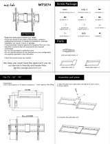
Rooftop installation - General
The data is provided without consideration to the installation location or the
pipe connections.
Standard dimensions for
determining the width of the
collector array
Length of mounting rail Alu + for 1 collector mounted on end 1030 mm
Length of mounting rail Alu + for 2 collectors mounted on end 2160 mm
Length of mounting rail Alu + for 3 collectors mounted on end 3290 mm
Length of mounting rail joiner: 100 mm
Collector width: 1100 mm
Distance between installed collectors: 31 mm
Installation on end (portrait)
Number of CFK-1 collectors 1 2 3 4 5 6 7 8 9 10
Collector array width [m] 1.1 2.23 3.36 4.49 5.62 6.75 7.89 9.02 10.15 11.28
Mounting rail length [m] 1.03 2.16 3.29 4.42 5.55 6.68 7.81 8.94 10.07 11.20
>15°

12
3062815_201508
Rooftop installation - General
The mounting rails can be extended by using mounting rail joiners.
One of the 3 screws of the mounting rail joiner set can also be used for securing
to a roof hook. For this, the U-rail remains centrally aligned; the screw can be
manoeuvred within the slot to the correct position above the hook.
Joining the mounting rails
Mounting rail for
2 collectors, e.g.
Mounting rail for one
additional collector, e.g.
Mounting rail
joining set
3 M8 x 25 coach bolts with M8 washer nuts
Preparatory installation
of roof hooks
Fitting roof hooks to battens
(installed before)
Top roof hooks Bottom roof hooks
M8 x 20
coach bolt
M8 x 20
coach bolt
M8 x 20
coach bolt
M8 washer nut
M8 washer nut
Short bracket
on top
Fitting roof hooks to rafters
(ret)
Initially tighten the roof hooks only by hand.
Top roof hooks Bottom roof hooks
Long bracket
on top
>15°
Note:
Sometileshapes(e.g.attilesthatareproledatthetopandbottom)must
becutoutintheareaoftheroofhookstoenablethettedroofhookstolie
correctly and to prevent the tile above from lifting up.
Recommendation:
We recommend the use of metal tiles below the roof hooks, particularly in
areas of high snowfall.

13
3062815_201508
Rooftop installation -
Interlocking tiles, plain tiles
1. Assemble the bottom roof hooks in acc. with the diagram and hook them
into the batten.
2. Assemble the top roof hooks in acc. with the diagram and hook them into
the batten.
Create the distance between both rails of 2.06 m for collector installation
on end or 1.06 m for collector installation across at the top roof hooks
using the slot in accordance with the diagram and secure that position with
M8 x 20 coach bolts.
3. AdjusttheheightofthexingbracketsandsecurewithM8x20coachbolts,
ensuring that the pressure is evenly distributed over the roof tiles.
4. SliptheM8x20coachboltsinsufcientnumbersintothemountingrails.
5. Fit the mounting rails with washer nuts onto the roof hooks.
6. Cover the roof hook area with tiles.
Collector across 1.06
Collector on end 2.06
Special features for interlocking or plain tile roofs
Roof hook installation on battens (example for 2 collectors)
Fitted bottom
roof hook
Collector array width
Mounting rail
Max. 0.4 m
rail protrusion
Max. 0.4 m
rail protrusion
Min. 3 rows
Mounting rail
Fitted top roof hook
M8 x 20 coach bolt
Mounting rail
If required, trim or bend
the roof hook over
Option
Snow load
extension set
Fit hooks bottom / top
Approx. central
Mounting rail
M8 x 20 coach bolt
M8 washer nut
Distribute all roof hooks supplied evenly over the width of the collector
array to spread the loads applied. For this, position the roof hooks as
near to the rafters as possible.
CAUTION
>15°

14
3062815_201508
Fitting the roof hooks to the rafters
(Example for 2 collectors)
1. Fit the bottom roof hooks in acc. with the diagram and secure them with
6 x 60 wood screws to the rafters.
2. Fit the top roof hooks in acc. with the diagram; adjust the distance between
both rails to 2.06 m when installing collectors on end or 1.06 m when installing
collectors across using the slot according to the diagram; secure with
M8 x 20 coach bolts and with 6 x 60 wood screws to the rafter.
3. AdjusttheheightofthexingbracketsandsecurewithM8x20coachbolts,
ensuring that the pressure is evenly distributed over the roof tiles.
4. SliptheM8x20coachboltsinsufcientnumbersintothemountingrails.
5. Fit the mounting rails onto the roof hooks.
6. Cover the roof hook area with tiles.
Fitted top roof hook
Fitted bottom roof hook
Mounting rail
Collector array width
M8 x 20 coach bolt
- Where the tile valley is not above a rafter, a separately available rafter
compensatingplate(3)isxedabovetherafter(2)andtheroofhook(1)
nestled in the valley is bolted to the compensating plate.
- Secure the compensating plates (3) with 6 x 60 wood screws and washers
onto the rafters (2).
- Insert the M8 x 20 coach bolt from below through the compensating rails.
- Position the roof hook and secure tightly with the hexagon nuts.
Mounting on rafters with
rafter compensating plate
Min. 3 rows
Max. 0.4 m
rail protrusion
Max. 0.4 m
rail protrusion
Collector across 1.06
Collector on end 2.06
If required, trim or bend the roof hook over
Mounting rail
Rooftop installation -
Interlocking tiles, plain tiles
Mounting rail
M8 x 20 coach bolt
M8 washer nut
Approx. central
Option
Snow load extension set
Fit hooks bottom / top
Distribute all supplied double-ended screws evenly over the width of the
collector array to spread the loads applied.
CAUTION
>15°
M8 x 20
coach bolts

15
3062815_201508
Rooftop installation - Slate tiles
Crosshead screw 6 x 70 mm
M8 x 20 coach bolt
M8 x 20 coach bolt
Mounting rail
M8 x 20
coach bolt
M8 washer nut
1. Removetheslateswherethehooksneedtobetted.
2. Secure the hooks with crosshead screws 6 x 70.
3. Fit mounting rails with coach bolts.
4. Covertheslatehookswithcommerciallyavailableleadashing.
5. Cover the roof.
Collector array width
Collector across 1.06
Collector on end 2.06
Option
Snow load
extension set
with hooks
Approx. central
Leadashing
Leadashing
Distribute all supplied double-ended screws evenly over the width of the
collector array to spread the loads applied.
CAUTION
Special features for rooftop installation on slate roofs with slate hooks
>15°

16
3062815_201508
Rooftop installation -
Corrugated roof
- Forroofscoveredincorrugatedroongsheets,drilltheholes(Ø14)into
theroofskinrespectivelyattheapexofthesheetprole.
- Maintain the vertical clearance between the holes for the double-ended
screws to safeguard the rail clearance.
- Ensurethesecurexingonthesub-structure/rafters.Whererequired,create
an additional sub-structure on site.
- Drill the holes for securing the double-ended screws in the rafters (Ø 8.5)
before commencing the installation. Insert a suitable rawl plug in case of
concrete or brickwork sub-structures.
- The double-ended screws must be inserted to a depth of between 80 and
100 mm. Lubrication makes the insertion easier. The smooth part of the
shank acts as sealing seat for the contact gasket. It must be located in the
area of the roof skin.
- The upper mounting plates point downwards; the lower mounting plates
point upwards. If the snow load extension set is used the double ended
screwsshouldbecutoffushwiththenut,abovethemountingplate.This
ensures that the collector housing does not come to rest on the screws.
- Theroofskinissealedbylightlyandcarefullytighteningtheangednut.
CorrugatedEternitroongsheetsmayotherwisefracture.Usellerelements
(on site) where necessary.
- We recommend the use of a thread-locking compound (e.g. Marston-Domsel
585.243) to prevent moisture entering along the thread and to secure the
positionoftheangenut.
Distribute all supplied double-ended screws evenly over the width of the
collector array to spread the loads applied.
CAUTION
Double-ended screw M12 x 300
Aluminium mounting plate 6 mm
EPDM gasket, UV-resistant
Filler piece (on site)
Flange nut,
remove carefully,
risk of breakage.
Fitting the
double-ended screw
Corrugated roof
Rail width
Collector across 1.19
Collector on end 2.19
Option
Snow load
extension set
Max. 0.4 m
rail protrusion
Max. 0.4 m
rail protrusion
Double-ended screw
with mounting plate
Approx. central
Special features for corrugated/sheet steel roofs with double-ended screws
>15°
Use thread-locking
compound to prevent
moisture entering

17
3062815_201508
Rooftop installation of collectors
1. Insert the collector with the grub screws in with the lower mounting rail
according to the diagram and initially secure it with the M8 washer nut by
hand.
2. Push the M8 x 20 combination screws through the top mounting rail and
initially tighten by hand into the collector.
3. Fit additional collectors likewise.
4. Securethettingsfortheowandreturn.Checkgaskets.
5. Tighten all screws and nuts to secure the collector.
- Are all gaskets in place?
- Maintain the necessary distance
- Alignallthreadedttings
- Counter hold with a second open-ended spanner max. torque 20 Nm
M8 x 20
combination screw
M8
grub screw
M8
washer nut
Collector mounting
>15°

18
3062815_201508
Roof integration - Interlocking tile
Standard delivery
Installation parts
Top skirts
Right hand skirt
Left hand skirt
Top mounting rail
Bottom mounting rail
(withreturnforashingtape)
Flashing tape base, right
Flashing tape
base, left
Flashing tape
Triangular
sealing strip
Edge
protector
Wooden spacer of
15 to 30 mm height to
match to the battens
Forsafetyreasons,the[German]roongcontractor’sassociationspeciesa
covered substrate with bitumen sheeting or other suitable material below the
collector area to prevent the ingress of moisture in case of leaks. This must
terminate in the roof gutter.
CAUTION
Screws, nuts,
grub screws,
wood screws in the bag
Intermediate
panels
Connecting rail
Standard dimensions for
determining the position of the
collector array
Position the collector array so that
the roof tiling can be completed as
far as possible using whole or half
tiles, without cutting.
Width of visible
sheet metal
Min. 3 rows
Min. 2.5 m
< 12 cm
Width incl. skirt
< 12 cm
Width incl. visible edging panels
Width incl. skirt
Number of collectors 1 2 3 4 5 6 7 8 9 10
Width incl. visible edging panels [m] 1.23 2.36 3.49 4.62 5.75 6.88 8.01 9.14 10.27 11.40
Width incl. skirt [m] 1.57 2.74 3.87 5.00 6.03 7.26 8.39 9.52 10.65 11.78
Tiles to be removed per
row of tiles:
Skirt width 30 cm 6 10 14 18 22 25 29 33 37 39
Skirt width 30 cm 8 12 18 24 29 35 41 46 52 58
Remove one extra row of tiles
to provide sufcient space for
installing.
30-60°

19
3062815_201508
Roof integration - Interlocking tile
Roof integration overview
Extension of the lower mounting rail
Flashing tape base, left Flashing tape base, rightConnecting rail
Mounting rail for
2 collectors (2.26 m)
Mounting rail for
1 add. collector (1.13 m)
2 x M8 x 16
coach bolts
4 x M8 x 16
coach bolts
Wooden spacers in the thickness of the battens
Triangular sealing strip
Top panel
Collector
Wooden spacers in the thickness
of the battens less 9 mm
Mounting rail
Flashing tape
Waterproof substrate
Recommendation:
Stuff the space below
the top panel at the tile
contact point to prevent
the tile from pushing
through.
30-60°

20
3062815_201508
Roof integration - Interlocking tile
30-60°
1. Afterttingtheextension,centrethemountingrailsothatagapoflessthan
12cmiscreatedonbothsidesbetweenthecollectorarrayandthenished
tiling. If this is not possible, use half tiles or cut tiles to size. Ensure that the
gap dimension remains <12 cm to ensure the roof cover is fully rainproof.
2. Drill a Ø 5 mm hole and secure the mounting rail with the hexagon head cap
wood screw 8 x 80 and the wooden spacers (batten thickness less 9 mm)
to the rafters.
3. Afxtheashingtapeinaccordancewiththediagram.Forthis,peelback
the protective foil only in the area actually to be used for the mounting rail.
Theashingtapemustprotrudeapprox.30cmontheleftandrightover
theashingtapebases.Secureseveralashingtapestoeachotherwith
anoverlapofatleast5cm.(Donotasyetafxtheashingtapetothetiles
as the collectors must still be secured to the mounting rail.)
8 x 80
Wooden spacer
(batten thickness less 9 mm)
Overlap > 5 cm
Mounting rail
Flashing tape
Installation of the lower mounting rail
Wooden spacer
(batten thickness
less 9 mm)
/