Page is loading ...

Installation, operating and
maintenance instructions
Rooftop installation with
AluPlus installation system
Roof integration
Flat roof installation with
AluPlus installation system
High performance solar collector
CFK-1
Art.no.3062815_0110Subjecttotechnicalmodications
GB
Wolf GmbH, Postfach 1380, 84048 Mainburg, Tel. 08751/74-0, Fax 08751/741600, Internet: www.wolf-heiztechnik.de

2
3062815_0110
Index
Index ..................................................................................................................... Page
1. Specication ..................................................................................................................3
2 Standards and regulations / Safety instructions ............................................................4
3. Information / Pipework examples ..................................................................................5
4. Information regarding the system hydraulics / Expansion vessels ...............................6
5. General preparations ...............................................................................................7 - 8
6. Rooftop installation (interlocking tile, plain tile) .............................................................9
- Standard delivery .......................................................................................................9
- Standard dimensions .................................................................................................9
- Snow loads ................................................................................................................9
7. Rooftop installation (interlocking tile, plain tile) roof hooks on battens .......................10
8. Rooftop installation (interlocking tile, plain tile) roof hooks on rafters ......................... 11
9. Rooftop installation (interlocking tile, plain tile) collector installation ...........................12
10. Special features to be considered for rooftop installation on slate roofs .....................13
11. Special features for rooftop installation
corrugated roof / sheet steel roof with double ended screws ......................................14
12. Supported on pitched roofs ..................................................................................15 - 17
- Information regarding the optimum collector angle of inclination .............................15
- Selection of hole size ...............................................................................................15
- Minimum clearance between several rows of collectors ..........................................16
- Standard dimensions ...............................................................................................17
13. Roof integration (interlocking tile) ........................................................................18 - 22
- Standard delivery .....................................................................................................18
- Standard dimensions ...............................................................................................18
- Collector installation .................................................................................................20
- Mounting intermediate panels/frames ...............................................................21 - 22
14. Roof integration (slate roof) .................................................................................23 - 29
- Standard delivery .....................................................................................................23
- Standard dimensions ...............................................................................................23
- Collector installation .................................................................................................25
- Mounting intermediate panels/frames ...............................................................26 - 29
15. Roof integration, high roof tiles (convex - concave tiles) .....................................30 - 35
- Standard delivery .....................................................................................................30
- Standard dimensions ...............................................................................................30
- Collector installation .................................................................................................32
- Mounting intermediate panels/frames ...............................................................33 - 35
16. Flat roof installation ..............................................................................................36 - 37
- Fixing information ....................................................................................................36
- Minimum clearance between several rows of collectors ..........................................36
- Standard dimensions ...............................................................................................37
- Installation of the support frame ..............................................................................37
17. Pipework / Filling the system / Safety datasheet ........................................................38
18. Leak testing / Commissioning .....................................................................................39
19. Commissioning check list ............................................................................................40
20. Operation / Service .....................................................................................................41
21. Service check list .................................................................................................42 - 43
Declaration of Conformity ..................................................................................................44

3
3062815_0110
Specication
Collector CFK-1
Casing Deep-drawn aluminium tray, natural,
sea-water resistant.
Dimensions (L x W x H) / (external edge) 2099 x 1099 x 110 mm
Gross surface area/surface exposed to wind
acc. to DIN 1055-4
2.3 m²
Effective absorber area 2.0 m²
Weight (dry) 36 kg
Content 1.1 litres
Absorber: Laser-welded aluminium absorber
Style: Harp, highly selective coating
Cover 3.0 mm solar safety glass, hail-proof *
Thermal insulation Mineral wool
Connections Flat-packing with union nut G ¾"
Angle of inclination 15° to 90°
Opticalefciency* 76.7%
Heatlosscoefcienta
1
* 3.669 W/(m K²)
Heatlosscoefcienta
2
* 0.018 W/(m² K²)
Stagnation temperature *
(permiss. operating temp.)
196 °C
Irradiation angle correction factor IAM-50 * 95%
Thermal capacity C * 7.78 kJ/(m² K)
Max. operating pressure 10 bar
Heat transfer medium ANRO ready-mixed (45% by vol.)
Recommended throughput 90 l / (h x number of collectors)
Pressure drop at 90 l/h * 1.5 mbar
Solar keymark register number ????????
* values to EN 12975 relative to the aperture area
1. Specication

4
3062815_0110
2. Standards and regulations /
Safety instructions
Observe the following regulations, rules and guidelines during
installation and operation.
Installation on roofs. Observe all current Health & Safety regulations
- EN 1991, 2-3 Snow loads
- EN 1991, 2-4 Wind loads
- DIN 1055-5 Snow loads
- DIN 1055-4 Wind loads
- DIN 18338 Roof covering and roof sealing work
- DIN 19339 Plumbing work
- DIN 18451 Scaffolding work
- BGV D 36 Ladders and steps
- BGR 203 Work on roofs
- BGR 198 Use of personal protection against falling
Connection of solar thermal systems
- EN 12976 Solar thermal systems and their components,
prefabricated systems (these include generally applicable
information regarding design and implementation)
- EN 12977 Solar thermal systems and their components,
bespoke systems (including generally applicable
information regarding engineering and implementation)
Installation and implementation of hot water heaters
- EnEV Pipework insulation
- DIN 18380 Heating water and DHW heating systems
- DIN 18381 Gas, water and waste water installation work
- DIN 18421 Heat insulation work on thermal systems
- AVB Water
Electrical connection
- VDE 0100 Installation electrical installations up to 1000 V
- VDE 0185, 1-4 Lightning protection systems
- ENV 61024 Operation of electrical power installations up to 1000 V
- VDE 0105 Cables and lines in buildings
- EN 50164-1 Lightning protection systems
The collectors are tested in accordance with the following standards:
EN 12975-2 Output testing for solar thermal collectors
Standards and regulations
The following symbols are used in conjunction with these important instructions
concerning personal safety, as well as operational reliability.
"Safety instructions" are instructions with which you must comply
exactly, to prevent injury and material losses.
the potentially very high temperatures inside the collector result in a
risk of scalding from the hot heat transfer medium.
"Please note" indicates technical instructions that you must observe
to prevent material losses and equipment malfunctions.
NB
Safety instructions

5
3062815_0110
3. Information / Pipework examples
Ideally, the collectors should be oriented between south-east and south-west
(optimum: south). Please refer to our technical advisors in case of an alternative
orientation. Trees, neighbouring structures, chimneys, etc. should throw as
little shade over the collectors as possible. Observe the different position of
the sun (summer/winter).
The clearance between the top edge of the solar collectors and the bottom
edgeofthegableshouldbeatleastthreetilesdeeptoenabletheowlineto
be rising inside the attic space.
In areas subject to heavy snow loads ensure that the snow can slide off the
collector. In other words, roof structures below the collector surface must be
avoided. For safety reasons, never damage cross battens or the tile under the
roof hooks (cracked, drilled, aged), otherwise they might break under extreme
snow loads. If in doubt, replace battens and / or tiles in these areas.
It would also be advantageous, when mounting the solar collectors on top of
the roof, if the tiles below the roof hooks were to be replaced by lead tiles.
Observe the snow load in accordance with EN 1991, 2-3 and DIN 1055-5.
Notes
Pipework examples A collector array consists of up to 10 collectors, when connecting pipework on
alternate sides.
Air trap (install at
the highest point)
Pipework on alternate sides
(up to 10 collectors are possible)
Pipework on alternate sides
(up to 10 collectors are possible)
Recommendation:
Piping several collector arrays in
accordance with Tichelmann

6
3062815_0110
4. System hydraulics expansion vessels
All details are recommendations and may differ from system to system.
Therefore, the diaphragm expansion vessel must be sized specically.
Information regarding the
system hydraulics
Thecollectorscanbeoperatedwithahighspecicthroughput(so-calledHigh-
Flow).Advantages:Thecollectoriswellcooled=highcollectorefciencylevel,
lowheatlossesattheowline.Disadvantages:Highpressuredrop=powerful
pump, large pipe cross-sections.
Throughput: High-Flow (90 l/h x coll), ANRO (45/55) 20 °C
Collector
number
Solar line
length
(m)
Solar
line
Ø (mm)
Pump
assembly
Cylinder
Expansion
vessel 2.5 bar
2
2
20 12 x 1 10 SEM-1-300 12
70 15 x 1 10 SEM-1-300 12
3
3
15 12 x 1 10 SEM-1-400 12
45 15 x 1 10 SEM-1-400 18
4
4
4
10 12 x 1 10 SEM-1-500 18
30 15 x 1 10 SEM-1-500 18
75 18 x 1 10 SEM-1-500 25
5
5
20 15 x 1 10 SEM-1-750 25
45 18 x 1 10 SEM-1-750 25
6
6
6
15 15 x 1 10 SEM-1-750 25
35 18 x 1 10 SEM-1-750 25
100 22 x 1 10 SEM-1-750 35
7
7
30 18 x 1 10 SEM-1-1000 35
70 22 x 1 10 SEM-1-1000 35
8
8
20 18 x 1 10 SEM-1-1000 35
60 22 x 1 10 SEM-1-1000 35
9
9
9
15 18 x 1 10 SEM-1-1000 35
45 22 x 1 10 SEM-1-1000 50
120 28 x 1.5 10 SEM-1-1000 50
10
10
25 22 x 1 10 SEM-1-1000 50
90 28 x 1.5 10 SEM-1-1000 50

7
3062815_0110
5. General preparations
-
Only handle and store the collector pile using the packing strips and pallets.
- Never move more than 16 collectors in a single pile and never store more
than 24 collectors in a single pile.
- Never move collectors with the glass facing down.
- To prevent damage, never carry collectors at the collector connectors or put
them down on the connectors.
- Never place the collector back onto uneven surfaces.
- Store collectors only in dry places that are free of dust.
- Cover the glass side of the collectors until the collectors are
commissioned.
- We recommend the use of transport handles (available as accessories).
NB
Transport and storage
The following tasks should be carried out prior to the collectors being moved
onto the roof (exception: Flat roof installation).
NB: Fit compensators only to the short connectors.
Connect the collectors alternately across (up to 10 collectors).
Prior to joining the connections, check whether the collector seals are inside
eachtting.
Whenttingtheconnectionpieces,compensatorsandplugs,alwayscounterhold
the union nut on the collector.
Removethesensorwellfromthecontrolunitcartonandinsertintotheow
connector.
Respectively insert 2 M8x30 grub screws fully into the lower tray edge.
Preparations prior to installation
Compensator
Grub screws
M8x30
Flow connection piece
Return connection
piece (obligatory for
roof integration)
Collector
gaskets
Sensor well
The following materials and tools are required for an easy and safe collector
installation:
1 Hammer
1 Tape measure
1 Pencil / chalk
2 Screwdrivers / spanner SW 13
1 Wood drill bit approx. 5 mm (only roof integration)
1 Angle grinder with stone cutting disc
2 Open-ended spanners SW 30
1 Adjustable pliers
1 Jig saw (where the roof is already planked in)
Roof outlets for the solar lines (e.g. ventilation tile; cut to size with an angle
grinder)
Protective conduits (sensor lead, pipework)
Anti-falling protection(s)
Crosshead bit
Required tools
Installation
The installation and commissioning must only be carried out by authorised contractors.
This contractor will be responsible for the correct installation and commissioning.
The collector connections, even those of dry collectors, can become very hot during the
installation. Wear protective gloves as there is a risk of injury from burns.

8
3062815_0110
5. General preparations
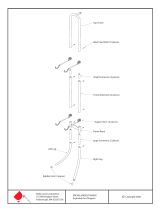
Roof hook installation in preparation of the rooftop installation
Fitting roof hooks to battens
(pre-assembled)
Fitting roof hooks to rafters
(ret)
Initially tighten the roof hooks
only by hand, as shown in the
diagram.
Top roof hooks Bottom roof hooks
Top roof hooks Bottom roof hooks
M8x20 coach bolt
M8x20 coach bolt
M8x20 coach bolt
When supporting the collectors on supports on pitched roofs, an installation
on battens is compulsory.
Washer nut
M8
Washer nut M8
Short leg
on top
Long leg
on top
Arrangement example: 3 collectors, on end, alternate connection
Flow connection piece
Return connector
(compulsory for
roof integration)
Are all gaskets in place?
1 x plug opposite
the connection
pieces
Grub screws M8x30 at the
bottom of the collectors
Compensators
Sensor well
Whenttingtheconnectionpieces,compensatorsandplugs,always
counterhold the union nut on the collector.
Removethesensorwellfromthecontrolunitcartonandinsertintotheow
connector. Respectively insert 2 M8x30 grub screws fully into the lower tray
edge.

9
3062815_0110
6. Rooftop installation
(interlocking tile, plain tile)
Distribute all roof hooks supplied evenly over the width of the collector
array to spread the loads applied. For this, position the roof hooks as
near to the rafters as possible.
NB
Positioning the collector
array for rooftop
installation
NB: No consideration has been given to the installation location or the pipe
connections.
Standard dimensions for
determining the width of the
collector array
Standard delivery, xing material subject to the number of:
Top roof hooks
withxingbrackets
Bottom roof hooks
withxingbrackets
Mounting rail
Mounting rail joint
set (if required)
Screws, nuts, grub
screws, woodscrews
in a bag
Compensating
rail set with
woodscrews for
mounting on rafters
Accessories
Number of collectors 1 2 3 4 5 6 7 8 9 10
Width [m] installation on end X 2.23 3.36 4.49 5.62 6.75 7.88 9.01 10.14 11.27
CFK-1 Without snow load extension set With snow load extension set
Max. area loading 2.4 kN/m² 4 kN/m²
Snow load zone 1 1190 m above sea level 1561 m above sea level
Snow load zone 1a 1039 m above sea level 1374 m above sea level
Snow load zone 2 768 m above sea level 1027 m above sea level
Snow load zone 2a 663 m above sea level 896 m above sea level
Snow load zone 3 587 m above sea level 799 m above sea level
Max. snow load when installing at-plate collectors on end with an inclination of 30° to 45°
This calculation takes a factor of 0.8 according to DIN 1055-5 into consideration (corresponding to a roof
inclination of 0° to 30°). We recommend roof integration where higher snow loads prevail.

10
3062815_0110
1. Assemble the bottom roof hooks as per the diagram and hook them onto
the batten.
2.
Assemble the top roof hooks as per the diagram and hook it onto the batten.
Create the distance between both rails of 2.06 m for collector installation on end at
the top roof hooks using the slot in accordance with the diagram and secure that
position with M8x20 coach bolts.
3. AdjusttheheightofthexingbracketsandsecurewithcoachboltsM8x20,
ensuring that the pressure is evenly distributed over the roof tiles.
4. Thread the coach bolts M8x20 in sufcient numbers into the mounting
rails.
5. Fit the mounting rails with washer nuts onto the roof hooks.
6. Cover the roof hook area with tiles.
7. Rooftop installation (interlocking tile,
plain tile) roof hooks on battens
Collector on end 2.06
Roof hook installation on battens (example for 2 collectors)
Fitted bottom
roof hook
Collector array width
Mounting rail
M8x20
coach bolt
Max. 0.4 m
Rail protrusion
Max. 0.4 m
Rail protrusion
Min. 3
rows
Mounting
rail
Fitted top roof hook
M8x20
coach bolt
Mounting
rail
If required, trim or bend
the roof hook over
Option
Snow load
extension set
Fit hooks bottom/top
approx.
central
Mounting rail
Coach bolt
M8x20
Washer nut
M8

11
3062815_0110
1. Fit the bottom roof hooks as per the diagram and secure them with 6x60
woodscrews to the rafters.
2. Fit the top roof hooks as per the diagram; adjust the distance between both
rails to 2.06 m when installing collectors on end using the slot according to
the diagram; secure with M8x20 coach bolts and with 6x60 woodscrews to
the rafter.
3. AdjusttheheightofthexingbracketsandsecurewithcoachboltsM8x20,
ensuring that the pressure is evenly distributed over the roof tiles.
4. Thread the coach bolts M8x20 in sufcient numbers into the mounting
rails.
5. Fit the mounting rails onto the roof hooks.
6. Cover the roof hook area with tiles.
8. Rooftop installation (interlocking tile,
plain tile) roof hooks on rafters
Fitting the roof hooks to the rafters
(example for 2 collectors)
Fitted top roof hook
Fitted bottom roof hook
Mounting rail
Collector array width
M8x20
coach bolt
M8x20
coach bolt
Min. 3
rows
Max. 0.4 m
Rail protrusion
Max. 0.4 m
Rail protrusion
Collector on end 2.06
If required, trim or bend
the roof hook over
Mounting rail
Mounting rail
Coach bolt
M8x20
Washer nut
M8
approx.
central
Option
Snow load
extension set
Fit hooks bottom/top
- Wherethetilevalleyisnotabovearafter,xcompensatingrails3supplied
above rafter 2. The roof hooks 1 are secured to the compensating rail in
the tile valley.
-
Secure compensating rail 3 with 6x60 woodscrews and washers on rafter 2.
- Insert the M8x20 coach bolt from below through the compensating rails.
- Position the roof hook and secure tightly with the hexagon nuts.
Fixing on rafters with
compensating rails
M8x20
coach bolt

12
3062815_0110
9. Rooftop installation (interlocking tile,
plain tile) collector installation
Note:Sometileshapes(e.g.attilesthatareproledatthetopandbottom)mustbecutoutintheareaoftheroof
hookstoenablethettedroofhookstoliecorrectlyandtopreventthetileabovefromliftingup.
Extension of the mounting rail
from 4 collectors
Ifmorethan3collectorsaretted,extendthemountingrailsinaccordance
with the diagram.
One of the three screws can also be used to secure the collector to a roof
hook. For this, the channel rail remains aligned in the centre; the screw can be
manoeuvred via the slot into the correct position above the hook.
Combination
screw
M8x20
Grub screw
M8
Washer
nut M8
Mounting rail,
e.g. for 3 collectors
Mounting rail, e.g. for
2 additional collectors
Mounting rail
joining set
3 coach bolts M8 x 25 with washer nuts M8
1.
Insertthecollectorwiththegrubscrewsrstintothelowermountingrailaccording
to the diagram and initially secure it by hand with the M8 washer nut.
2. Push the combination screws M8x20 through the top mounting rail and
initially tighten by hand into the collector.
3. Fit additional collectors likewise.
4. Securethettingsfortheowandreturn.Checkgaskets.
5. Tighten all screws and nuts to secure the collector.
- Are all gaskets in place?
- Maintain the necessary clearance
- Alignallthreadedttings
- Counterhold with a second
open-ended spanner
(max. torque 20 Nm.)
NB

13
3062815_0110
10. Special features for rooftop installation
on slate roofs with slate hooks
1. Remove the slates where the hooks
needtobetted.
Collector array width
Crosshead screw 6x70 mm
M8x20 coach bolt
2. Secure the hooks with crosshead screws 6x70 mm.
M8x20 coach bolt
Collector on end 2.06
3. Covertheslatehookswithcommerciallyavailableleadashing.
4. Cover the roof.
Distribute all roof hooks supplied evenly over the width of the collector
array to spread the loads applied.
NB
Option
Snow load
extension set
with hooks
Mounting rail
Coach bolt
M8x20
Washer nut
M8
approx.
central
Max. 0.4 m
Max. 0.4 m

14
3062815_0110
11. Rooftop installation on corrugated / sheet
steel roofs with double ended screws
- Forroofscoveredincorrugatedroongsheets,drillthehole(Ø14)forthe
double ended screws into the roof skin respectively at the apex of the sheet
prole.
- Maintain the vertical clearance between the holes for the special headless
screws to safeguard the rail clearance.
- Ensurethesecurexingonthesub-structure/rafters.Whererequired,create
an auxiliary sub-structure on site.
- Drill the holes for securing the special headless screws in the rafters
(Ø 8.5) before commencing the installation. Insert a suitable rawl plug in
case of concrete or brickwork sub-structure.
- The special headless screws must be inserted to a depth of between 80
and 100 mm. Lubrication makes the insertion easier. The smooth part of the
shank acts as the sealing seat for the contact gasket. It must be located in
the area of the roof skin.
- For improved stability, the mounting plates for the special headless screws
are oriented upwards.
- Theroofskinissealedbylightandcarefultighteningoftheangednut.
Otherwise there is a risk that the corrugated Eternit roong sheets will
fracture.
General notes
Distribute all supplied special headless screws evenly over the width of
the collector array to spread the loads applied.
NB
Double ended screw M12x300
Aluminium mounting plate 6 mm
EPDM gasket, UV-resistant
Tightenangenut
carefully
Risk of
breakage
Fitting the special
headless screw
Corrugated roof
Collector array width
Collector on end 2.06
Option
Snow load
extension set
Max. 0.4 m
Rail protrusion
Max. 0.4 m
Rail protrusion
Special headless
screw with mounting
plate
approx.
central

15
3062815_0110
12. Supported on pitched roofs
Optimum angle of inclination Toadjusttheangleofinclinationsubjecttothemethodofutilisation,theexible
supporting triangles can be matched to the relevant optimum angle.
Thesupportingtrianglesarettedwithholesat20°,30°and45°andcanbe
trimmed to size subject to the pitch of the roof.
Fixing information The roof hooks must be tted on rafters if the collectors are supported on
pitched roofs. First check the structural suitability of the sub-structure and
the permissible area loading for the roof (if required call on the services of a
structural engineer). Take the height of the building into consideration.
The collectors should be positioned at least 1 m away from the edge of the
roof to make the installation easier and due to the higher wind forces near the
edge of the roof.
Selection of hole size
2.06 m for on end installation
45°
30°
20°
Fit the diagonal leg to the respective hole in the vertical leg, subject to the required
angle.
Mark the vertical leg above the diagonal leg and trim to size (see diagram).
Wind
Wind energy Fw
Wind
Height of
building
Area exposed
to wind
Wind energy
Fw
0 – 8 m 2.30 m
2
2030 N
8 – 20 m 2.30 m
2
2800 N
> 20 m 2.30 m
2
Individual calculation acc. to EN 1991,
2-4 and DIN 1055-4 required
Information regarding the
optimum collector angle of
inclination
Solar DHW heating 30° ± 5°
Combined systems for solar DHW heating
and solar central heating backup
45° ± 5°
Solar heating backup 55° ± 5°
The following optimum collector angle of inclination is recommended, subject
to use:

16
3062815_0110
12. Supported on pitched roofs
Extension of the mounting rail
from 4 collectors
Ifmorethan3collectorsaretted,extendthemountingrailsinaccordance
with the diagram.
Mounting rail,
e.g. for 3 collectors
Mounting rail, e.g. for
2 additional collectors
Mounting rail
joining set
3 coach bolts M8 x 25 with washer nuts M8
Hole dimension "h"
Minimum clearance between
several rows of collectors
d1
d
>1m
>1m
d
a
Roof inclination
α(°)
Support angle
δ (°)
Angle of inclination
to the horizontal (°)
Hole dimension "h"
(cm)
Clearance
dimension "d1" (cm)
Clearance
dimension "d" (cm)
15 30 45 117 (existing) 162 336
20 10 30 32 47 245
20 25 45 98 114 296
20 40 60 153 173 327
25 20 45 80 (existing) 77 266
30 15 45 62 49 243
30 30 60 117 (existing) 94 268
40 20 60 80 (existing) 45 234
45 15 60 62 28 222
Minimum clearance and angle for the supports when installing the collector on end (example: Würzburg)

17
3062815_0110
NB: No consideration has been given to the installation location or the pipe
connections.
Standard dimensions for
determining the width of the
collector array
12. Supported on pitched roofs
Installation of the support frame
Rafter centre
Installation on end:
Diagonal brace
Combination
screw
Washer nut
M8
2.06 on end
installation
M8x20
coach bolt
Washer nut
M8
M8x20
coach bolt
Washer nut
M8
Diagonal brace When supporting collectors on pitched roofs, t
one diagonal brace (snow load rail) per row of
collectors.
Vertical leg
Washer nut M8
M8x20 coach bolt
Diagonal brace
(snow load rail)
Number of collectors 1 2 3 4 5 6 7 8 9 10
Width [m] installation on end X 2.23 3.36 4.49 5.62 6.75 7.88 9.01 10.14 11.27
1. Fit the roof hooks on rafters; for this, observe the vertical and horizontal
hook clearances.
2. Fit the supporting triangles onto the roof hooks.
3. Secure the mounting rails at the bottom / top of the support frame using
M8x50 hexagon nuts.
4. Insertthecollectorwiththegrubscrewsrstintothelowermountingrail
according to the diagram and initially secure it by hand with the M8 nut and
washer.
5. Push the M8x20 hexagon screws with washers through the top mounting
rail and initially tighten by hand into the collector.
6. Fit additional collectors likewise.
7. Securethettingsfortheowandreturn.Checkgaskets.
8. Install 1x snow load rail per collector array as diagonal brace.
9. Tighten all screws and nuts to secure the collector.
- Are all gaskets in place?
- Maintain the necessary
clearance
- Alignallthreadedttings
- Counterhold with a second
open-ended spanner.
(max. torque 20 Nm.)
NB
Max. 0.4 m
Max. 1.2 m
Max. 1.2 m
Max. 0.4 m
Further collectors approx. 1.13 m
Max. 1 m

18
3062815_0110
13. Roof integration, interlocking tile
Forsafetyreasons,the[German]roongcontractor'sassociationspeciesa
covered substrate with bitumen sheeting or other suitable material below the
collector area to prevent the ingress of moisture in case of leaks. This must
terminate in the roof gutter.
Standard dimensions for
determining the position of
the collector array
Collector array width
Min. 3 rows
Min. 2.5 m
X (0.5-12 cm)
Width with cover frame
X (0.5-12 cm)
Collector array width
Width with cover frame
Standard delivery
Installation parts
Top cover panels
Right hand
cover panel
Left hand
cover panel
Top mounting rail
Bottom mounting rail
(withreturnforashingtape)
Flashing tape base, R.h.
Flashing tape
base L.h.
Flashing tape
Triangular
sealing tape
Edge
protector
Timber spacer of 15 to 30 mm
height to match to the battens
Screws, nuts, grub screws,
woodscrews in a bag
Intermediate
panels
Connecting rail
Number of collectors 2 3 4 5 6 *) 7 8 9 10 *)
Width of the collector array [m] 2.36 3.49 4.62 5.75 6.88 8.01 9.14 10.27 11.40
Width with cover frame [m] 2.74 3.87 5.00 6.03 7.26 8.39 9.52 10.65 11.78
*)Tiles to be removed per row of tiles:
Cover width 30 cm 8 14 18 22 25 29 33 37 39
Dim. "X" [cm] 0.5 4 7.5 11 14.5/ 7 3 6.5 10 6
Cover width 20 cm 12 18 24 29 35 41 46 52 58
Dim. "X" [cm] 0.5 4 7.5 1 4.5 8 1.5 5 8.5
*) After "centring" the mounting rail we recommend to shift the rail 7 cm to the left or right. This ensures that on one side half a tile and on the
opposite side a whole tile can be used.
NB

19
3062815_0110
13. Roof integration, interlocking tile
1. Centrethemountingrailafterttingtheextension,sothatagapof0.5-12cm(dim."X")iscreatedbetweenthe
collectorarraywidthandthenalcover.Wheredim."X"cannotbeachieved,usehalftilesorcuttilestosize.
Dim. "X" must be achieved to ensure a cover that is safe from the ingress of rain.
2. Drill a Ø 5 mm hole and secure the mounting rail with the hexagon head cap wood screw 8x80 and the timber
spacers (batten thickness less 9 mm) to the rafters.
3. Afxtheashingtapeinaccordancewiththediagram.Forthis,removetheprotectivefoilonlyintheareaactuallyto
beusedforthemountingrail.Theashingtapemustprotrudeapprox.35cmontheleftandrightovertheashing
tapebases.Secureseveralashingtapestoeachotherwithanoverlapofatleast5cm.(Donotasyetafxthe
ashingtapetothetilesasthecollectorsmuststillbesecuredtothemountingrail.)
Installation and extension
of the lower mounting rail
(withreturnforashingtape)
Flashing tape
base, L.h.
Flashing tape base, R.h.
Connecting rail
Mounting rail for
2 collectors (2.26 m)
Mounting rail for
1 add. collector (1.13 m)
2 x coach bolt
M8 x 16
4 x coach bolt
M8 x 16
8 x 80
Timber spacer
(batten thickness less 9 mm)
Overlap > 5 cm
Mounting
rail
Flashing tape
Construction
Timber spacers in the thickness of the battens
Triangular sealing tape
Top panel
Collector
Timber spacers in the thickness of
the battens less 9 mm
Mounting rail
Flashing tape
Waterproof subroof
Recommendation:
Stuff the space below the
top panel at the tile contact
point to prevent the tile from
pushing through.

20
3062815_0110
13. Roof integration, interlocking tile
1. Insertthecollectorwiththegrubscrewsrstintothelowermountingrail
according to the diagram and initially secure by hand with the M8 nut with
washer.
2. Insert additional collectors likewise into the lower mounting rail.
3. Position the timber spacers (batten height) onto the rafters at the top of the
collectors. Position the mounting rail on top of the timber spacers and push
against the top of the collector. Initially secure the mounting rail with the
combination screws M8x20 and washers by hand to the collectors.
4. Drill a Ø 5 mm hole through the mounting rail and the wood spacers into the
rafter and secure to the rafter with hexagon head cap wood screw 8x80.
5. Securethettingsfortheowandreturn.Checkgaskets.
6. Check for leaks in accordance with the section "Leak testing"
Collector installation
Timber spacer
(batten height)
8 x 80
Flashing tape
Washer
nut M8
Timber spacer
(batten height less 9 mm)
Combination screw
M8x20
Bottom mounting rail
Top mounting rail
Top mounting rail
- Are all gaskets in place?
- Maintain the necessary clearance
- Alignallthreadedttings
- Counterhold with a second open-ended
spanner (max. torque 20 Nm.)
NB
/