Page is loading ...

SNODO PER RIVELATORI IR15 / DT15
BRACKETS FOR DETECTORS IR15 / DT15
GELENK FÜR BEWEGUNGSMELDER IR15 / DT15
ROTULE POUR DETECTEUR IR15 / DT15
SOPORTE ARTICULADO PARA DETECTORES
IR15 / DT15
PORTOGHESE JUNTA PARA DETETOR IR15 / DT15
ITALIANO ENGLISH
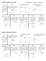
Far scorrere il cavo attraverso il particolare A. Fissare il
particolare A alla parete o al soffitto con le viti in dotazione al
sensore, mantenendo la ”Linguetta di bloccaggio” sulla
sinistra (fig.1). Comporre lo snodo inserendo il particolare B
nel particolare A (fig.1)
Orientare il particolare B in uno dei due sensi parete / soffitto
secondo il montaggio desiderato (fig. 2, 3 e 4).
Incidere totalmente, le preforature “Fissaggio Snodo“ e
“Passacavo Snodo“ sul fondo plastico (fig.5).
Con la vite fornita fissare il fondo plastico allo snodo e
dirigere il cavo verso il basso. Orientare il fondo plastico nella
direzione voluta e bloccare stringendo la vite. Rimontare il
circuito sul fondo plastico.
Run the cable through Grip A. Fix it at the wall or at the ceiling
whit the furnished screws keeping the Blocking Hack on the
left side (fig.1). Make up the bracket inserting the Grip B in
the Grip A (fig.1).
Position the Grip B on the desired mounting mode Wall /
Ceiling (fig. 2, 3 and 4). Engrave, totally, the keyholes
“Bracket clamping” and “Bracket cable hole” on the back
cover (fig.5).
With the furnished screw fix the back cover on the bracket
and arrange the cable down.
Direct the back cover to the wanted direction. Then block it
by clamping the screw.
Put the circuit on the plastic bottom.
DEUTSCH FRANCAIS
Das Kabel durch das Einzelteil A gleiten lassen. Das
Einzelteil A an der Wand oder der Decke mit den im
Lieferumfang des Sensors enthaltenen Schrauben
anbringen und dabei den "Sperrzahn" links halten (Abb. 1).
Das Gelenk zusammensetzen, indem das Einzelteil B in das
Einzelteil A eingesetzt wird (Abb. 1)
Entsprechend der gewünschten Montage das Einzelteil B in
eine der beiden Richtungen (Wand/Decke) bringen (Abb. 2,
3 und 4).
Die vorgelochten Öffnungen "Gelenkbefestigung" und
"Kabeldurchgang Gelenk" auf dem Kunststoffboden
durchbrechen (Abb. 5).
Mit der im Lieferumfang enthaltenen Schraube den
Kunststoffboden am Gelenk anbringen und das Kabel nach
unten führen. Den Kunststoffboden in die gewünschte
Richtung bringen und durch Anziehen der Schraube
blockieren. Den Stromkreis wieder auf dem Kunststoffboden
anbringen.
Faire passer le câble à travers la pièce A. Fixer la pièce A à
la paroi ou au plafond à l’aide des vis fournies avec le
détecteur, en maintenant la ”Patte de blocage” à gauche
(fig.1). Composer la rotule en insérant la pièce B dans la
pièce A (fig.1).
Orienter la pièce B dans l’une des deux directions
paroi/plafond, selon le montage souhaité (fig. 2, 3 et 4).
Percer totalement les pré-perçages “Fixation rotule“ et
“Passe-câble rotule“ sur le fond en plastique (fig.5).
A l’aide de la vis fournie, fixer le fond en plastique à la rotule
et diriger le câble vers le bas. Orienter le fond en plastique
dans la direction souhaitée et le bloquer en serrant la vis.
Reposer le circuit sur le fond en plastique.
ESPAÑOL
PORTUGUÊS
Hacer pasar el cable por la pieza A. Fijar la pieza A en la
pared o en el techo con los tornillos entregados con el
sensor, manteniendo la “Lengüeta de bloqueo” a la
izquierda (fig. 1). Armar el soporte colocando la pieza B en
la pieza A (fig. 1).
Orientar la pieza B en uno de los dos sentidos pared / techo,
según el montaje deseado (fig. 2, 3 y 4).
Cortar totalmente, los troquelados “Fijación soporte“ y
“Pasacables soporte“ del fondo plástico (fig. 5).
Con el tornillo entregado, fijar el fondo plástico en el soporte
articulado y dirigir el cable hacia abajo. Orientar el fondo
plástico en el sentido deseado y bloquear apretando el
tornillo. Montar nuevamente el circuito sobre el fondo
plástico.
Fazer o cabo passar pela peça A. Fixar a peça A na parede
ou no teto usando os parafusos fornecidos e mantendo a
”Lingueta de bloqueio” à esquerda (fig.1). Montar a junta
inserindo a peça B na peça A (fig.1)
Orientar a peça B num dos dois sentidos, parede / teto,
segundo a montagem desejada (fig. 2, 3 e 4).
Cortar completamente os furos “Fixação da Junta“ e “Canal
do Cabo da Junta“ da base de plástico (fig.5).
Fixar com o parafuso fornecido a base de plástico na junta e
direcionar o cabo para baixo. Orientar a base de plástico na
direção desejada e bloquear apertando o parafuso. Montar
novamente o circuito na base de plástico.
LBT80947
-
DS80SP1E
-
001

Soffitto
Ceiling
Decke
Plafond
Techo
Teto
1
Particolare A
Grip A
Einzelteil A
Pièce A
Pieza A
Peça A
Particolare B
Grip B
Einzelteil B
Pièce B
Pieza B
Peça B
Linguetta di bloccaggio
Blocking Hack
Sperrzahn
Patte de blocage
Lengüeta de bloqueo
Lingueta de bloqueio
2 3
Parete
Wall
Wand
Paroi
Pared
Parede
SNODO A PARETE
WALL BRACKET
WANDGELENK
ROTULE MURALE
SOPORTE DE PARED
JUNTA DE PAREDE
Cavo
Cable
Kabel
Câble
Cable
Cabo
Fissaggio snodo
Bracket clamping
Gelenkbefestigung
Fixation rotule
Fijación soporte
Fixação da junta
4
SNODO A SOFFITTO
CEILING BRACKET
DECKENGELENK
ROTULE AU PLAFOND
SOPORTE DE TECHO
JUNTA DE TETO
5
Cavo
Cable
Kabel
Câble
Cable
Cabo
Passacavo snodo
Bracket cable hole
Kabeldurchgang Gelenk
Passe-câble rotule
Pasacables del soporte
Canal do cabo da junta
ASSEMBLAGGIO SNODO
BRACKET ASSEMBLING
GELENKMONTAGE
ASSEMBLAGE ROTULE
ENSAMBLAJE SOPORTE ARTICULADO
M
ONTAGEM DA JUNTA
/