FA00270M4A - ver. 1 - 03/2018
General Precautions
• Important people-safety instructions: READ CAREFULLY!
• Installing, programming, commissioning and maintenance must
only be done by qualified, expert sta and in full compliance with
applicable laws.
• Wear antistatic protective clothing when working on the control
board.
• Keep these precautions.
• Always cut o the mains power when doing cleaning and main-
tenance jobs.
• This product must only be used for its specifically intended purpo-
se. Any other use is dangerous.
• The manufacturer declines all liability for any damage as a result of
improper, incorrect or unreasonable use.
Description
Double-technology, volumetric detector with one MW (micro-wave)
section and one PIR (passive infrared) section with pet immunity fun-
ction adjustable on two levels, either up 12 or up to 20 kg. In ECO
mode the microwave can be switched o if the room is occupied.
Description of parts A
1 Swivel
2 Swivel screw
3 Plastic base
4 Tab
5 Base opening slit
F Control board
Technical data
Type PXDTVPI
Power supply (V DC) 9 to 15
Maximum absorption when in alarm memory
(mA) 22
Absorption when idle (mA) 8
Microwave frequency (Ghz) 10.525
Microwave power (dBm) 8
Alarm time (s) 3
Alarm-contact range at 24 V (mA) 100
Tamper-contact range at 30 V (mA) 100
theoretic MTBF (h) 120,000
Installing height (m) 2.1 to 2.3
Range (m) 12
Coverage arc (°) 90
Number of beams across four levels (n) 18
Dimensions (mm) 107x61.5x43
Operating temperature (°C) -10 to +55
Regulatory compliance: EN50131-2-4 GRA-
DE 2, CLASS II
Guide to installing
Install the sensor while considering the characteristics of the room you
are going to protect so as to install it in the most eective position to
provide maximum coverage. Corner installations are always best. Po-
sition the sensor facing into the room, away from any doors, windows,
moving machinery and heat sources. Keep it turned away from any
sun-exposed window panes. Do not tilt the sensor downwards so as
not to compromise the pet immunity function.
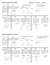
Fitting
Remove the plastic shell by using a screwdriver to lightly press and
detach it E. Remove the circuit board F by bending one of the
tabs 4.
TO WALL/IN CORNER
To corner fit the device, drill the marked areas A1 and A2 marked
areas. and to wall fit the device, do the same to the P1 or P2 marked
areas B.
Drill one of the holes inthe (PC) Cable gland on the bottom of the
plastic base B. Drill 6 mm fastening holes into the wall, and run the
cable through the chosen cable gland. Fasten the base to the wall
by using the supplied screws and dowels. These must not touch the
control board. Refit the circuit board onto the plastic base.
WITH SWIVEL (do not tilt downwards for pet immunity)
Run the cable through part G and fasten it to the wall or ceiling using
the supplied screws, while keeping the locking tab I to the left.
Fit part H to part G and turn it all the way in one direction, depen-
ding on how you have fitted the device to the wall K, E or ceiling
J, F.
Completely perforate the FS 'swivel fastening' parts and the PCS
'swivel cable-gland' parts B and fasten the base to the swivel while
keeping the cable downwards. Turn the plastic base in the desired
direction and lock it by tightening the screw B. Refit the circuit board.
Terminal board Q
+ -/12 V Input for 12 V power supply
NC/ALL NC alarm relay
IINPUT: input for detecting whether the system is armed
or not
NC/TAMP NC tamper contact
WalkTest
When powered up the sensor is in Walk Test mode and will display the
microwave and the infrared detections and the state of the alarm. This
check will last 20 minutes. At the end, the alarms will be displayed if
Dip-switch 2 is ON (the blue LED lights up M); if Dip-switch 2 is OFF,
the alarms stored in the memory will be displayed.
Microwave test
Adjust the potentiometer P (range 0.5 to 12 m) depending on the
room it is protecting. Walk about the area you want protected and
check that the green MW LED L lights up at each walk about.
NOTE. The microwave range should be set to minimum so as to de-
tect any disturbances even beyond the protected area. For example
outside of the room being protected and so as not to compromise the
pet immunity.
PIR Test
Fit the sensor's front panel and, with the LEDs o, move about the
area it is meant to protect and verify whether the PIR is detecting by
checking the yellow LED N.
H Detection diagram
AUTOMATIC ECO operation
The sensor, by monitoring any motion in the room, establishes
whether the system is armed or not, without the INPUT terminal being
connected. This is to reduce to a minimum any microwave emissions
when the system is disarmed and thus not needlessly radiate people
in the room while not losing any detection sensitivity, or any immunity
to false alarms.
How the PET IMMUNITY works
Dip-switch 1 - adjust PET immunity and detection range
OFF
Maximum range and field of detection. For animals up to wei-
ghing 12 Kg. In rooms where the temperature exceeds 10° C
ON
Range reduced to 10 m. For pets weighing up to 20 kg. In
rooms where the temperature exceeds 10° C
Functions with input line
This set of functions are activated/deactivated by arming or disarming
the system.
It is
deemed as 12 V on the
INPUT= system disarmed 0 V on the INPUT= system armed.
Alarm relay block
When the system is disarmed, the alarm relay is blocked in the NC
condition.
Remotely enabled LED
When the system is disarmed, the sensor sets up to restore the de-
tection viewings. The viewings will be restored to the first actual de-
tection, and remain active for 30 seconds.
ECO function-switching o the microwave
When the system is disarmed and with Dip-switch 2 set to ON, the
microwave will be disabled so as not to needlessly radiate the room
it is protecting. The microwave will be restored once the system is
armed again.
Memories
When the system is turned o, the memory of the first alarm triggered
will be displayed, as per the table shown below. The memory will be
reset once the system is armed again.
Memory delay for using in timer zones
Exiting time: Any alarms that sound within the first 30 seconds after
arming the system, will be deleted.
Entering time: any alarms that sound within the first 30 seconds of
disarming the system, will be deleted.
Viewing in memory state
ALARM GREEN LED BLUE LED YELLOW LED
PIR+MW OFF ON OFF
PIR OFF ON ON
MW ON ON OFF
This product complies with the law.
Decommissioning and disposal. Dispose of the packaging and the
device at the end of its life cycle responsibly, in compliance with the
laws in force in the country where the product is used. The recyclable
components are marked with a symbol and the material's ID marker.
THE DATA PRESENTED IN THIS MANUAL MAY BE CHANGED, AT ANY
TIME, AND WITHOUT NOTICE. MEASUREMENTS, UNLESS OTHERWISE
STATED, ARE IN MILLIMETERS.
ENGLISH
Instructions générales
• Instructions importantes pour la sécurité des personnes : À
LIRE ATTENTIVEMENT !
• L’installation, la programmation, la mise en service et l'entretien
doivent être eectués par du personnel qualifié et dans le plein res-
pect des normes en vigueur.
• Porter des vêtements et des chaussures antistatiques avant d'in-
tervenir sur la carte électronique.
• Conserver ces instructions.
• Toujours couper le courant électrique durant les opérations de net-
toyage ou d'entretien.
• Ce produit ne devra être destiné qu'à l'utilisation pour laquelle il
a été expressément conçu. Toute autre utilisation est à considérer
comme dangereuse.
• Le fabricant décline toute responsabilité en cas d'éventuels dommages
provoqués par des utilisations impropres, incorrectes et déraisonnables.
Description
Détecteur volumétrique bi-technologie avec une section à micro-onde
(MW) et une section à infrarouge passif (PIR), immunité aux animaux
réglable sur deux niveaux (12 ou 20 Kg). La modalité ECO permet
d’éteindre la micro-onde lorsque la pièce est occupée.
Description des parties A
1 Rotule
2 Vis de la rotule
3 Fond plastique
4 Patte
5 Fente d’ouverture du fond
6 Carte
Données techniques
Type PXDTVPI
Alimentation (VDC) 9÷15
Absorption max. en mémoire d'alarme (mA) 22
Absorption au repos (mA) 8
Fréquence micro-onde (Ghz) 10,525
Puissance micro-onde (dBm) 8
Temps d'alarme (s) 3
Portée contact d'alarme à 24 V (mA) 100
Portée contact autoprotection à 30 V (mA) 100
MTBF théorique (h) 120,000
Hauteur d'installation (m) 2,1÷2,3
Portée (m) 12
Couverture (°) 90
Nombre de faisceaux sur 4 plans (n) 18
Dimensions (mm) 107x61,5x43
Température de fonctionnement (°C) de -10 à +55
Conformité norme : EN50131-2-4
DEGRÉ 2, CLASSE II
Guide d’installation
Analyser les caractéristiques de la pièce à protéger de manière à
identifier la position du capteur permettant une couverture maximale.
Toujours préférer une installation en angle. Positionner le capteur vers
l’intérieur de la pièce, à l’écart de portes, fenêtres, machines en mou-
vement et sources de chaleur, et ne pas le diriger vers des surfaces
vitrées exposées au soleil. Ne pas incliner le capteur vers le bas de
manière à ne pas compromettre l’immunité aux animaux.
Fixation
Enlever la base en plastique à l’aide d’un tournevis et appuyer légè-
rement pour la décrocher 5. Extraire le circuit 6 en écartant une
des pattes 4.
MURALE/EN ANGLE
Percer les zones préforées A1 et A2 pour la fixation en angle et P1 ou
P2 B pour la fixation murale.
Percer un des trous (PC) prévus sur la base en plastique B pour le
passage du câble. Percer les trous de fixation (6 mm) dans le mur et
faire passer le câble à travers le passe-câble. Fixer la base au mur à
l’aide des vis et des chevilles fournies sans que celles-ci ne touchent
la carte électronique. Remettre le circuit dans la base en plastique.
AVEC ROTULE (ne pas incliner vers le bas pour l’immunité des
animaux)
Faire passer le câble à travers l’élément 7 et le fixer au mur ou
au plafond à l’aide des vis fournies, en maintenant la languette de
fixation 9 à gauche.
Introduire l’élément 8 dans l’élément 7 et l’orienter dans l’un des
deux sens en fonction de l’installation souhaitée (au mur K, E ou
au plafond J, F).
Percer complètement les parties FS (fixation rotule) et PCS (passe-
câble rotule) B puis fixer la base à la rotule en dirigeant le câble vers
le bas. Orienter la base en plastique dans le bon sens et la bloquer en
serrant la vis 2. Remettre circuit.
Bornier Q
+ -/12 V Entrée alimentation 12 V
NC/ALL Relais alarme NF
IINPUT : entrée reconnaissance installation activée/dé-
sactivée
NC/TAMP Contact autoprotection NF
Essai de marche
Le capteur, qui s’allume en mode « essai de marche », visualisera les
détections de la micro-onde, de l’infrarouge ainsi que l’état d’alarme.
Ce contrôle durera 20 minutes. Au terme du contrôle, l’écran a-
chera les alarmes en cas de micro-interrupteur 2 sur ON (allumage
de la LED bleue M) ; en cas de micro-interrupteur 2 sur OFF, l’écran
achera les alarmes mémorisées.
Test micro-onde
Régler le potentiomètre P (portée 0,5 m-12 m) en fonction de l’es-
pace à protéger. Se déplacer dans la zone à protéger en contrôlant
que la LED verte MW L s’allume bien à chaque passage.
REMARQUE. Régler la portée de la micro-onde au minimum pour pou-
voir détecter également des brouillages au-delà de la zone à protéger
(ex. : à l’extérieur du local à protéger) et pour ne pas compromettre
l’immunité des animaux.
Test PIR
Appliquer la partie frontale du capteur et, avec les leds éteintes, se
déplacer dans la zone protégée en s’assurant de la détection eective
du PIR indiquée par la led jaune N.
H Diagramme de détection
Fonctionnement AUTOMATIC ECO
Par le biais du contrôle des mouvements dans la pièce, le capteur
est en mesure d’établir si l’installation est ou n’est pas activée sans
que la borne INPUT ne soit connectée. Il est ainsi possible de limiter
au maximum les émissions de la micro-onde lorsque l’installation est
désactivée et de ne pas irradier inutilement les personnes présentes
dans le local et ce, sans aucune perte de sensibilité de détection ni
d’immunité contre les fausses alarmes.
Fonctionnement PET IMMUNITAIRE
DIP1 - Réglage PET immunitaire et portée de détection
OFF
Portée maximale et champ de détection. Pour des animaux
pesant jusqu'à 12 Kg. Dans des locaux où la température
dépasse les 10°C
ON
Portée réduite à 10 m. Pour des animaux pesant jusqu'à 20
Kg. Dans des locaux où la température dépasse les 10°C
Fonctions avec ligne input
Ces fonctions sont activées/désactivées moyennant l’activation/dé-
sactivation de l’installation.
En particulier :
12 V sur l’entrée INPUT= installation désactivée
0 V sur l’entrée INPUT= installation activée.
Blocage relais d'alarme
À la désactivation de l’installation, le relais d’alarme reste NF.
Activation à distance LED
À la désactivation de l’installation, le capteur permet le réachage
des diagrammes de détection. Le réachage aura lieu à la première
détection et durera 30 s.
Fonction ECO-extinction de la micro-onde
Lorsque l’installation est désactivée et que le micro-interrupteur 2 est
sur ON, la micro-onde est elle aussi désactivée pour ne pas irradier
inutilement l’espace à protéger. La micro-onde sera de nouveau acti-
vée à la prochaine activation de l’installation.
Mémoires
La mémoire visualisée à la désactivation de l’installation est celle de
la première alarme, comme indiqué dans le tableau ci-dessous. La
mémoire sera remise à zéro à la prochaine activation de l’installation.
Retard de la mémoire pour une utilisation dans des zones tem-
porisées
Temps de sortie : les alarmes qui se déclenchent durant les 30
premières secondes à compter de l’activation de l’installation sont
eacées.
Temps d’entrée : les alarmes qui se déclenchent 30 secondes avant
la désactivation de l’installation sont eacées.
Visualisation en état de mémoire
ALARME LED VERTE LED BLEUE LED JAUNE
PIR+MW ÉTEINTE ALLUMÉE ÉTEINTE
PIR ÉTEINTE ALLUMÉE ALLUMÉE
MW ALLUMÉE ALLUMÉE ÉTEINTE
Ce produit est conforme aux directives de référence en vigueur.
Mise au rebut et élimination. Ne pas jeter l'emballage et le dispositif
dans la nature au terme du cycle de vie de ce dernier, mais les éliminer
selon les normes en vigueur dans le pays où le produit est utilisé. Le
symbole et le sigle du matériau figurent sur les composants recyclables.
LES DONNÉES ET LES INFORMATIONS CONTENUES DANS CE MANUEL
SONT SUSCEPTIBLES DE SUBIR DES MODIFICATIONS À TOUT MOMENT
ET SANS AUCUN PRÉAVIS. LES DIMENSIONS SONT EXPRIMÉES EN MIL-
LIMÈTRES, SAUF INDICATION CONTRAIRE.
FRANÇAIS
Общие предупреждения
• Важные правила техники безопасности: ПРОЧИТАЙТЕ ВНИ-
МАТЕЛЬНО! • Монтаж, программирование, ввод в эксплуатацию и
техническое обслуживание должны производиться квалифицирован-
ным и опытным персоналом в полном соответствии с требованиями
действующих норм безопасности. • Используйте антистатическую
одежду и обувь при работе с электроникой. • Храните данные ин-
струкции. • Всегда отключайте электропитание перед выполнением
работ по чистке или техническому обслуживанию системы. • Это
изделие должно использоваться исключительно по назначению.
Любое другое применение рассматривается как опасное. • Фир-
ма-изготовитель снимает с себя всякую ответственность за ущерб,
нанесенный неправильным, ошибочным или небрежным использо-
ванием изделия.
Описание
Комбинированный охранный извещатель, состоящий из пассив-
ного инфракрасного датчика и СВЧ-датчика, с двухуровневой
настройкой невосприимчивости к животным небольших разме-
ров (12 или 20 кг). В режиме ECO можно выключить СВЧ-датчик,
если помещение занято.
Основные компоненты A
1 Шарнирное крепление
2 Винт шарнира
3 Пластиковое основание
4 Крепление
5 Щелевое отверстие в основании
F Плата
Технические характеристики
Модель PXDTVPI
Напряжение электропитания (=В) 9-15
Макс. потребляемый ток в режиме сигна-
лизации (мА) 22
Потребляемый ток в режиме ожидания (мА) 8
Частота микроволнового излучения (ГГц) 10,525
Мощность микроволнового излучения (дБм) 8
Время работы сигнализации (с) 3
Макс. нагрузка на контакты сигнализации
при 24 В (мA) 100
Макс. нагрузка на контакты датчика сабо-
тажа при 30 В (мA) 100
Средняя наработка на отказ (в часах) 120,000
Высота установки (м) 2,1-2,3
Дальность действия (м) 12
Угол охвата (°) 90
Количество пучков на 4 уровнях (шт.) 18
Габаритные размеры (мм) 107x61,5x43
Диапазон рабочих температур (°C) -10 — +55
Соответствует стандарту
EN50131-2-4, КЛАСС
2, КЛАСС ОПАСНО-
СТИ ДЛЯ ОКРУЖАЮ-
ЩЕЙ СРЕДЫ II
Инструкция по монтажу
Установите извещатель и проанализируйте характеристики охраняемо-
го помещения, чтобы определить оптимальное положение датчика для
обеспечения максимального охвата. Установка под углом всегда явля-
ется предпочтительной. Установите извещатель вдали от дверей, окон,
подвижных механизмов и источников тепла. Направьте датчик внутрь
помещения, избегая ориентации в сторону окон, характеризующихся
прямым попаданием солнечного света. Не наклоняйте извещатель вниз
во избежание снижения невосприимчивости системы к животным.
Крепление
С помощью отвертки снимите пластиковую фронтальную накладку,
слегка надавив по бокам E. Вытащите электронную плату F, сме-
стив вбок одно из креплений 4.
НАСТЕННЫЙ/УГЛОВОЙ МОНТАЖ
Для углового монтажа пробейте отверстия в точках A1 и A2 , а для
настенного монтажа — в точке P1 или P2 B.
Пробейте одно из отверстий для гермоввода (PC), предусмотренных
в пластиковом основании B. Рассверлите отверстия диаметром
6 мм для установки устройства на стену и протяните кабель через
выбранный гермоввод. Зафиксируйте основание на стене прилагае-
мыми винтами и дюбелями. Обратите внимание на то, чтобы они не
касались электронной платы. Установите плату обратно на пласти-
ковое основание.
С ШАРНИРОМ (не наклоняйте вниз для сохранения невосприим-
чивости к животным)
Протяните кабель через деталь G и зафиксируйте устройство на
стене или потолке прилагаемыми винтами, удерживая язычок бло-
кировки I слева.
Вставьте H в G и поверните его в одном из двух направлений в
зависимости от того, устанавливается извещатель на стену K, E
или на потолок J, F.
Полностью рассверлите детали FS (шарнирного крепления) и PCS
(гермоввода шарнира) B и прикрепите основание к шарниру, пере-
местив провод вниз. Поверните пластиковое основание в требуемом
направлении и заблокируйте его, затянув винт B. Установите обрат-
но плату.
Клеммная колодка Q
+ -/12 V Вход электропитания 12 В
NC/ALL Релейные контакты тревожной сигнализации, нормаль-
но-замкнутые
IINPUT: вход определения включенной/выключенной
системы
NC/TAMP Контакты датчика саботажа, нормально-замкнутые
Тест на движение
При включении извещатель находится в режиме «Тест на движение» и
показывает индикацию СВЧ-датчика, ИК-датчика и статус тревожных
сигналов. Эта проверка займет 20 минут. По ее завершении будут
показаны тревожные сигналы, если DIP-переключатель 2 установлен
в положение «ВКЛ.» (загорается синий светодиодный индикатор M);
если DIP-переключатель 2 установлен в положение «ВЫКЛ.», будут
показаны тревожные сигналы, сохраненные в памяти.
Тест СВЧ-датчика
Отрегулируйте потенциометр P (дальность 0,5 м - 12 м) с учетом
особенностей охраняемого помещения. Перемещайтесь по охраняе-
мой территории, следя за тем, чтобы зеленый индикатор MW L заго-
рался при каждом прохождении.
ПРИМЕЧАНИЕ. Дальность обнаружения СВЧ-датчика устанавливается
на минимальное значение, достаточное для обнаружения помех за
пределами охраняемой территории (например, снаружи охраняемого
помещения) и сохранения невосприимчивости к животным.
Тест ПИК-датчика
Установите фронтальную накладку извещателя и, при выключенных
светодиодных индикаторах, перемещайтесь по охраняемой террито-
рии, следя за тем, чтобы ПИК-датчик вас обнаруживал, на что указы-
вает желтый индикатор N.
H Схема обнаружения
АВТОМАТИЧЕСКИЙ РЕЖИМ РАБОТЫ ECO
Путем мониторинга перемещений в пространстве извещатель
определяет, включена система или нет, без подключения к контак-
там INPUT. Это позволяет максимально ограничить использование
СВЧ-излучения при выключенной системе и, следовательно, свести
к минимуму облучение людей в помещении, без ущерба для чувстви-
тельности обнаружения и защиты от ложного срабатывания.
Режим работы PET IMMUNITY
DIP1 - Регулировка невосприимчивости к домашним животным
и дальности обнаружения
OFF
Максимальная дальность и зона обнаружения. Для животных
массой до 12 кг. При температуре окружающей среды 10°C
ON
Дальность снижена до 10 м. Для животных массой до 20 кг.
При температуре окружающей среды 10°C
Функции с линией INPUT
Эти функции активируются/отключаются при взятии системы под
охрану и снятии с нее.
Это предполагает следующее:
12 В на входе INPUT= система выключена
0 В на входе INPUT= система включена.
Блокировка реле тревожной сигнализации
При выключении системы реле тревожной сигнализации блокируется
в нормально-замкнутом состоянии.
Удаленное включение светодиодных индикаторов
При снятии системы с охраны извещатель готовится к повторному
включению светодиодной индикации обнаружения. Индикация активи-
руется при первом обнаружении и остается активной в течение 30 с.
Режим ECO-выключения СВЧ-датчика
При выключенной системе и DIP-переключателе №2 в положении
«ВКЛ.» СВЧ-датчик будет выключен для защиты охраняемого поме-
щения от бессмысленного излучения. Работа СВЧ-датчика возобнов-
ляется при последующем включении системы.
Память тревожных состояний
При снятии системы с охраны появится светодиодная индикация
первого тревожного события из памяти состояний, как показано в
приведенной ниже таблице. Сброс памяти будет осуществлен при
последующем взятии системы под охрану.
Задержка памяти для использования в зонах с таймером
Время выхода: тревожные сигналы, полученные в течение первых 30
секунд после взятия системы под охрану, удаляются.
Время входа: тревожные сигналы, полученные в течение 30 секунд
перед снятием системы с охраны, удаляются.
Индикация из памяти состояний
ТРЕВОГА ЗЕЛЕНЫЙ ИНДИ-
КАТОР
СИНИЙ ИНДИ-
КАТОР
ЖЕЛТЫЙ ИН-
ДИКАТОР
ПИК + СВЧ ВЫКЛЮЧЕН ВКЛЮЧЕН ВЫКЛЮЧЕН
ПИК ВЫКЛЮЧЕН ВКЛЮЧЕН ВКЛЮЧЕН
СВЧ ВКЛЮЧЕН ВКЛЮЧЕН ВЫКЛЮЧЕН
Изделие соответствует требованиям действующих норм безопас-
ности.
Утилизация. Не выбрасывайте упаковку и устройство в окружа-
ющую среду. Утилизируйте их в соответствии с требованиями за-
конодательства, действующего в стране установки. Компоненты,
пригодные для повторного использования, отмечены специальным
символом с обозначением материала.
КОМПАНИЯ CAME S.P.A. СОХРАНЯЕТ ЗА СОБОЙ ПРАВО НА ИЗМЕ-
НЕНИЕ СОДЕРЖАЩЕЙСЯ В ЭТОЙ ИНСТРУКЦИИ ИНФОРМАЦИИ В
ЛЮБОЕ ВРЕМЯ И БЕЗ ПРЕДВАРИТЕЛЬНОГО УВЕДОМЛЕНИЯ. ВСЕ
РАЗМЕРЫ ПРИВЕДЕНЫ В ММ, ЕСЛИ НЕ УКАЗАНО ИНОЕ.
РУССКИЙ