Page is loading ...

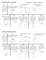
SPA10 - SNODO PER RIVELATORI SERIE IRA/IMA
SPA10 - ROTULE POUR DETECTEUR SERIES IRA/IMA
MONTAGGIO A PARETE / MONTAGE AU
MUR
Brandeggio Orizzontale: ±42°
Brandeggio Verticale: -86° ÷ +15°
Pivotement Horizontal: ±42°
Pivotement Vertical: -86° ÷ +15°
MONTAGGIO A SOFFITTO / MONTAGE
AU PLAFOND
Brandeggio orizzontale: ±42°
Brandeggio verticale: -11 ÷ +92°
Pivotement horizontal: ±42°
Pivotement vertical: -11 ÷ +92°
L’utilizzo della vite a corredo
assicura il corretto blocca
gg
io
del fondo del rivelatore allo
snodo, in conformità alle
norme CEI 79.2.
L’utilisation de la vis
de fermeture est
indispensable pour
assurer le correct
blocage de la rotule.
Attenzione: la vite di
blocco del movimento
va inserita nella sede
più distante rispetto
al dado di serraggio.
Attention : la vis de blocage
du mouvement doit être
placée dans le perçage le
plus distant par rapport a
l’écrou de serrage.
ITALIANO FRANCAIS
INSTALLAZIONE
Aprire l’apposita predisposizione a sfondamento ed
assemblare lo snodo come indicato in figura. Inserire il
cavo (diametro max 6 mm) attraverso il foro dello snodo e
fissare a muro o a soffitto con due tasselli. Una volta
individuata la posizione più favorevole alle esigenze
dell’area di copertura, è necessario serrare completamente
il dado con una chiave da 15, con coppia di serraggio
compresa tra 1 e 1,5 Nm; bloccare il movimento dello
snodo serrando a fondo la vite fornita a corredo ed infine
chiudere il coperchio del sensore.
INSTALLAZIONE KIT TAMPER SPA10
Alloggiare il tamper sul retro dello snodo come illustrato; far
passare i due fili attraverso il foro dello snodo e collegarli in
serie alla linea sabotaggio.
ATTENZIONE: In ottemperanza a quanto disposto dalle
norme CEI 79/2, l’installazione del kit tamper deve
essere eseguita come segue:
1) rimuovere la molla dal tamper;
2) predisporre sul muro un tassello (non fornito) e
regolare la vite affinchè, in presenza dello snodo, sia
premuto il tamper;
3) fissare lo snodo a muro.
INSTALLATION
Faire pression sur le point de rupture prévu et assembler la
rotule comme illustré sur la figure. Faire passer le fil
(diamètre maxi 6 mm) à travers l’orifice de la rotule et le
fixer au mur ou au plafond avec deux chevilles. Après avoir
localisé la position la plus favorable aux exigences du
champ de couverture, il s’avère nécessaire de serrer à
fond l’écrou à l’aide d’une clé de 15, avec un couple de
serrage compris entre 1 et 1,5 Nm; pour finir, refermer la
calotte du détecteur.
INSTALLATION DU KIT TAMPER SPA10
Loger le tamper à l’arrière de la rotule comme illustré ci-
contre; faire passer les deux fils à travers l’orifice de la
rotule et les relier en série à la ligne sabotage.
ATTENTION: Pour une installation correcte du kit
tamper sur le mur il faut:
1) retirer le ressort du tamper;
2) préparer une cheville (pas fourni) sur le mur et
régler la vis de manière à ce que le tamper reste
enfoncé en présence de la rotule;
3) fixer la rotule au mur.
IS1190-
A
B
V
ITE
/
VIS
KIT TAMPER SPA10
SPA 10 TAMPER KIT
ELKRON S.p.A.
Via Cimarosa, 39 – 10154 Torino (TO) – ITALY
Tel. +39(0)113986711 – FAX +39(0)113986790
www.elkron.it mal to: [email protected]
DS80IR75-001_LBT80145

SPA10 - BRACKET FOR IRA/IMA SERIES DETECTORS
SPA10 - GELENKSTÜCK FÜR IRA/IMA BEWEGUNGSMELDER
WALL FASTENING / WANDMONTAGE
Horizontal traverse: ± 42°
Vertical traverse: – 86° ÷ +15°
Horizontale Schwenkung: ±42°
Vertikale Schwenkung: -86° ÷ +15°
CEILING FASTENING /
DECKENMONTAGE
Horizontal traverse: ± 42°
Vertical traverse: – 11° ÷ +92°
Horizontale Schwenkung: ±42°
Vertikale Schwenkung: -11 ÷ +92°
L’utilizzo della vite a corredo
assicura il corretto blocca
gg
io
del fondo del rivelatore allo
snodo, in conformità alle
norme CEI 79.2.
L’utilisation de la vis
de fermeture est
indispensable pour
assurer le correct
blocage de la rotule.
Attenzione: la vite di
blocco del movimento
va inserita nella sede
più distante rispetto
al dado di serraggio.
Attention : la vis de blocage
du mouvement doit être
placée dans le perçage le
plus distant par rapport a
l’écrou de serrage.
ENGLISH DEUTSCH
INSTALLATION
Open the special knock-down provision and assemble the
bracket as illustrated in the figure. Put in the cable
(diameter: max. 6 mm) through the bracket hole, then
fasten it to the wall or ceiling by making use of two dowels.
After the most advantageous position to the covering area
requirements has been identified, the nut should be
tightened down to 1 to 1.5 Nm by means of a wrench (size:
15), then the detector cover should be closed.
SPA10 TAMPER KIT INSTALLATION
Place the tamper at the bracket rear, as illustrated in the
figure. Allow the two wires to pass through the bracket hole,
and then connect them in series to the anti-tampering line.
CAUTION! The correct installation for tamper kit is the
following:
1) remove the spring from the tamper;
2) place a dowel (not supplied) onto the wall, then
adjust the screw so that the tamper can be pressed
when the bracket is present;
3) fasten the bracket to the wall.
INSTALLATION
Den vorbereiteten Durchbruch öffnen und das Gelenk, wie
abgebildet, zusammenbauen.
Das Kabel (Durchmesser max. 6 mm ) durch die
Gelenköffnung ziehen und mit zwei Dübeln an der Wand
oder Decke befestigen. Nachdem der geeignete Platz zur
Absicherung des Bereichs ermittelt wurde, ist die Mutter
mit einem 15-Schlüssel fest anzuziehen, mit
Anzugsmoment zwischen 1 und 1,5 Nm; zuletzt dann den
Deckel des Sensors schliessen.
TAMPER KIT SPA10 INSTALLATION
Den tamper, wie abgebildet, an der Rückwand des
Gelenks einbetten. Die beiden Drähte durch den
Durchbruch im Gelenk ziehen und diese in Reihe zur
Sabotageleitung schalten.
ACHTUNG! die korrekte Installation des tamper kit für
den Entfernungsschutz ist das folgende:
1) Feder vom tamper entfernen;
2) An der Wand einen Dübel (nicht lieferte) vorbereiten
und die Schraube so einregulieren dass, bei
vorhandenem Gelenk, der tamper angepresst wird;
3) Gelenkstück an der Wand befestigen.
KIT TAMPER SPA10
SPA 10 TAMPER KIT
V
ITE
/
VIS
ELKRON S.p.A.
Via Cimarosa, 39 – 10154 Torino (TO) – ITALY
Tel. +39(0)113986711 – FAX +39(0)113986790
www.elkron.it mal to: [email protected]
DS80IR75-001_LBT80145
IS1190-AB
/