FA01046M4A - ver. 1 - 02/2018
General Precautions
Important people-safety instructions: READ CAREFULLY!
• Installing, programming, commissioning and maintenance must
only be done by qualified, expert sta and in full compliance with
applicable laws.
• Wear antistatic protective clothing when working on the control
board.
• Keep these precautions.
• Always cut o the mains power when doing cleaning and main-
tenance jobs.
• This product must only be used for its specifically intended purpo-
se. Any other use is dangerous.
• The manufacturer declines all liability for any damage as a result of
improper, incorrect or unreasonable use.
There is danger of the battery exploding if it is replaced with
the wrong type.
• Once the batteries are flat, dispose of in accordance with the
law.
Description
Battery-powered, infrared, volumetric, radio-frequency sensor, featu-
ring tearing and opening tampering protection.
Description of parts A B
A Front piece
B Tear-proof protection
3 Alert LED
4 Radio card
E Opening tampering-protection
F Buzzer
G Button for self-learning
H Infrared sensor
I DIP switches
J Battery-brace
K Swivel
L Swivel screw
M Base
N Tab
O Base opening slot
P Control board
LEDs
Color Meaning
Red Tampering and alarm
Green Tamper protection restored
Technical data
Input voltage
one 3 V 1700 mAh (CR123A) lithium
battery
Absorption when on standby
(uA)
20
Radio signal strength (dBm)
Range (m)
200 m in open air (@ 868.65 MHz)
100 m in open air (@ 433.92 MHz)
Infrared coverage (°)
90° divided into 4 levels and 18
sectors
Operating temperature (°C) -10÷55
Dimensions (mm) 107x61.5x43
Protection rating (IP) 30
Regulatory compliance
EN50131-2-2, EN50131-5-3,
EN50131-6: Type C, EN50130-5,
Grade 2
Environmental class II
Programming
Fit the battery into the brace and start making settings, selections and
tests on the Dip-Switches.
SW1
Dip 1 (Walk Test)
OFF
After a detection, it
turns o after three
minutes
ON Transmits continuously
upon each detection
(Walk Test)
Dip 2 (Detection sensitivity)
OFF Standard ON Less sensitive
Dip 3 (1) Radio signal strength
OFF Standard ON Weaker radio si-
gnal-strength
Dip 4 (2) Enable/disable LED
OFF Disabled ON Enabled
Dip 5 (3) Enable/disable BUZZER
OFF Disabled ON Enabled
Dip-switch 6 Enable/disable tear-proof tamper device
OFF Enabled ON Disabled
(1) run a test with the strength set to weaker to make sure the system
works even when the signal is weaker. Reset the Dip-switch to OFF.
(2) The LED flashes when the sensor shifts into alarm;
(3) If the battery is flat, the BUZZER will emit four beeps;
NOTE. Once programming is complete and upon each subse-
quent change, press the self-learning button.
Installing
Before fitting the sensor, make sure the room is free of any sources of
sensor malfunctions, such as:
- direct sunlight or rain;
- vibrating surfaces;
- pets;
heat sources.
Covering the four levels H
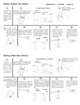
Fitting
If the sensor is attached to the wall, enable the tear-proof
tampering device. Broaden the 'FF' hole (≥ 5mm) G and fit the
supplied spring onto the tear-proof tampering device 2. Set
Dip-switch 6 to OFF.
EN50131 regulatory compliance is met if the sensor is
mounted without the swivel and the tear-proof tamper device
is enabled.
Use a screw driver to remove the front piece. Lightly press down onO
and remove the control board P by bending one of the tabs N.
TO WALL/IN CORNER
To wall-mount, cut the P1 or P2 marked areas. To corner-mount, cut
the A1 and A2 marked areas. C.
Drill 6mm holes into the wall and fasten the base to the wall bu using
the supplied screws and plugs. Make sure they do not touch the con-
trol board. Refit the control board onto the base close the sensor.
ON SWIVEL
Fit part Q to the wall or ceiling by using the supplied screws. Keep
the locking tab S on the left. Fit part R to part Q and turn it towards
the chosen detection zone , or to the ceiling T.
Drill the wall FS (swivel fastening) C and fasten the base to the swi-
vel. Turn the base towards the chose detection zone. Fasten the swivel
with a screw L. Refit the control board onto the plastic bottom and
close the sensor.
Learning
The sensor's self-learning can be done in two ways:
- via PC by using the PXManager software I, by selecting [SENSOR]
in the [MODEL] column and entering the serial number (printed on the
battery brace G) in the [SERIAL] column;
- manually via keyboard making sure that the control unit is in self-le-
arning mode.
CAME S.p.A.declares that this device complies with directive
2014/53/EU. You can find the complete wording of the EU declaration
of conformity at: www.came.com.
Decommissioning and disposal. Dispose of the packaging and the
device at the end of its life cycle responsibly, in compliance with the
laws in force in the country where the product is used. The recyclable
components are marked with a symbol and the material's ID marker.
THE DATA PRESENTED IN THIS MANUAL MAY BE CHANGED, AT ANY
TIME, AND WITHOUT NOTICE. MEASUREMENTS, UNLESS OTHERWISE
STATED, ARE IN MILLIMETERS.
ENGLISH
Общие предупреждения
Важные правила техники безопасности: ПРОЧИТАЙТЕ ВНИ-
МАТЕЛЬНО!
• Монтаж, программирование, ввод в эксплуатацию и техниче-
ское обслуживание должны производиться квалифицирован-
ным и опытным персоналом в полном соответствии с требова-
ниями действующих норм безопасности.
• Используйте антистатическую одежду и обувь при работе с
электроникой.
• Храните данные инструкции.
• Всегда отключайте электропитание перед выполнением работ
по чистке или техническому обслуживанию системы.
• Это изделие должно использоваться исключительно по назна-
чению. Любое другое применение рассматривается как опасное.
• Фирма-изготовитель снимает с себя всякую ответственность
за ущерб, нанесенный неправильным, ошибочным или небреж-
ным использованием изделия.
Опасность взрыва при замене батарейки на элемент пита-
ния неправильного типа.
• По истечении срока службы батарейки должны быть собра-
ны отдельно и переданы авторизованной компании для по-
следующей утилизации. Запрещается выбрасывать батарей-
ки с обычным или дифференцированным бытовым мусором.
Описание
Беспроводной комбинированный охранный извещатель (СВЧ +
ИК) с питанием от батарейки и антисаботажной защитой (датчи-
ками вскрытия и снятия со стены).
Основные компоненты A B
A Передняя крышка
B Датчик снятия с поверхности
3 Светодиодные индикаторы
4 Плата радиоприемника
E Датчик вскрытия корпуса
F Зуммер
G Кнопка автоматического обнаружения
H ИК-извещатель
I Dip-переключатели
J Держатель батарейки
K Шарнир
L Винт шарнира
M Основание
N Крепление
O Отверстие открывания основания
P Плата
LED-ИНДИКАТОРЫ
Цвет Значение
Красный Датчик и сигнализация
Зеленый Сброс сигнализации
Технические характеристики
Электропитание
1 литиевая батарейка, 3 В,
1700 мАч (CR123A)
Макс. потребляемый ток (мА)
Потребляемый ток в режиме
ожидания (мкА)
20
Мощность радиосигнала (дБм)
Дальность действия (м)
200 м на открытом простран-
стве (на частоте 868,65 МГц)
100 м на открытом простран-
стве (на частоте 433,92 МГц)
Угол охвата ИК-лучей (°)
90°, поделенных на 4 плоскости
и 18 секторов
Диапазон рабочих темпера-
тур(°C) -10-55
Габаритные размеры (мм) 107x61,5x43
Класс защиты (IP) 30
Соответствует стандарту
EN50131-2-2, EN50131-5-3,
EN50131-6: тип C, EN50130-5,
класс 2
класс опасности для окружаю-
щей среды II
Программирование
Вставьте батарейку в отсек и выполните все необходимые регу-
лировки, настройки и проверки с помощью DIP-переключателей.
SW1
Dip 1 (Walk Test)
OFF
После обнаружения
происходит отключе-
ние на 3 минуты
ON Постоянная передача
при каждом обнаруже-
нии (Walk Test)
Dip 2 (Чувствительность обнаружения)
OFF Стандартная ON Снижение чувствитель-
ности
Dip 3 (1) Мощность радиосигнала
OFF Стандартная ON Снижение мощности
радиосигнала
Dip 4 (2) Включение/выключение светодиодного индикатора
OFF Отключено ON Включено
Dip 5 (3) Включение/выключение ЗУММЕРА
OFF Отключено ON Включено
DIP 6 Включение/отключение ДАТЧИКА снятия со стены
OFF Включено ON Отключено
(1) Выполните тестирование при сниженной мощности радио-
сигнала, чтобы убедиться в том, что система работает даже при
плохом качестве сигнала. Установите DIP-переключатель в
положение OFF.
(2) Светодиодный индикатор мигает, когда срабатывает сигнали-
зация извещателя.
(3) Если батарейка разряжена, ЗУММЕР сообщит об этом 4 зву-
ковыми сигналами.
ПРИМЕЧАНИЕ. По завершении программирования и при ка-
ждом последующем изменении нажимайте кнопку автома-
тического обнаружения.
Монтаж
Перед тем как установить охранный извещатель, необходимо
убедиться в том, что в окружающем пространстве нет помех,
которые могут повлиять на его работу, в числе которых:
- прямое попадание солнечных лучей/дождя;
- поверхности, склонные к вибрации;
- присутствие животных;
- источники тепла.
Охват 4 плоскостей H
Крепление
Если извещатель устанавливается на стену, включите
ДАТЧИК снятия со стены. Увеличьте отверстие (≥ 5 мм) 'FF' G
и установите прилагаемую пружину на датчик снятия со сте-
ны 2. Установите DIP-переключатель № 6 в положение OFF.
Требования норматива EN50131 будут соблюдены только
в том случае, если монтаж выполняется без использования
шарнира и включен ДАТЧИК снятия со стены.
Снимите переднюю крышку с помощью отвертки. Слегка надави-
те O и вытащите плату P , сдвинув вбок одно из креплений N.
НАСТЕННЫЙ/УГЛОВОЙ МОНТАЖ
Для настенного монтажа сделайте отверстия в точках P1 и P2.
Для углового монтажа сделайте отверстия в точках A1 и A2 C.
Рассверлите отверстия диаметром 6 мм в стене и зафиксируйте
основание на стене прилагаемыми винтами и дюбелями. Обра-
тите внимание на то, чтобы они не касались электронной платы.
Установите плату обратно на основание и закройте извещатель.
МОНТАЖ С ШАРНИРНЫМ КРЕПЛЕНИЕМ
Прикрепите деталь Q к стене или потолку прилагаемыми вин-
тами, удерживая язычок блокировки S слева. Вставьте деталь
R в Q и поверните ее в зависимости от того, монтируется он
на стене или потолке T. Рассверлите отверстие в точке FS
(крепление шарнира) C и прикрепите основание к шарниру. По-
верните основание под требуемым углом и зафиксируйте шарнир
винтом L. Установите плату обратно на пластиковое основание
и закройте извещатель.
Обнаружение устройств
Обнаружение охранного извещателя может быть выполнено двумя
способами:
- с ПК посредством программного обеспечения PXManager I, выбрав
[ДАТЧИК] в колонке [МОДЕЛЬ] и указав серийный номер (приведен-
ный на суппорте батарейки G) в колонке [СЕРИЙНЫЙ НОМЕР];
- вручную с помощью кнопочной панели, предварительно убедившись
в том, что контрольная панель системы охранной сигнализации нахо-
дится в режиме определения устройства.
CAME S.p.A. заявляет, что это устройство соответствует требованиям Дирек-
тивы 2014/53/UE. Полный текст декларации о соответствии доступен по следу-
ющему адресу: www.came.com.
Утилизация. Не выбрасывайте упаковку и устройство в окружающую среду.
Утилизируйте их в соответствии с требованиями законодательства, действую-
щего в стране установки. Компоненты, пригодные для повторного использова-
ния, отмечены специальным символом с обозначением материала.
КОМПАНИЯ CAME S.P.A. СОХРАНЯЕТ ЗА СОБОЙ ПРАВО НА ИЗМЕНЕНИЕ СО-
ДЕРЖАЩЕЙСЯ В ЭТОЙ ИНСТРУКЦИИ ИНФОРМАЦИИ В ЛЮБОЕ ВРЕМЯ И БЕЗ
ПРЕДВАРИТЕЛЬНОГО УВЕДОМЛЕНИЯ. ВСЕ РАЗМЕРЫ ПРИВЕДЕНЫ В ММ, ЕСЛИ
НЕ УКАЗАНО ИНОЕ.
РУССКИЙ
Instructions générales
Instructions importantes pour la sécurité des personnes : À LIRE
ATTENTIVEMENT !
• L’installation, la programmation, la mise en service et l'entretien
doivent être eectués par du personnel qualifié et dans le plein res-
pect des normes en vigueur.
• Porter des vêtements et des chaussures antistatiques avant d'in-
tervenir sur la carte électronique.
• Conserver ces instructions.
• Toujours couper le courant électrique durant les opérations de net-
toyage ou d'entretien.
• Ce produit ne devra être destiné qu'à l'utilisation pour laquelle il
a été expressément conçu. Toute autre utilisation est à considérer
comme dangereuse.
• Le fabricant décline toute responsabilité en cas d'éventuels dom-
mages provoqués par des utilisations impropres, incorrectes et dé-
raisonnables.
Ne remplacer la pile usagée que par une pile compatible afin
d'éviter tout risque d'explosion.
• Ne pas jeter les piles à la poubelle au terme de leur cycle de
vie, mais les collecter séparément en vue d'un recyclage correct.
Description
Capteur volumétrique radio à infrarouge, alimenté par pile, avec dis-
positif de protection anti-sabotage et anti-arrachement.
Description des parties A B
1 Partie frontale
2 Autoprotection anti-arrachement
3 Voyant led de signalisation
4 Carte radio
5 Autoprotection anti-sabotage
6 Buzzer
7 Bouton d’autoapprentissage
8 Capteur à infrarouge
9 Micro-interrupteurs
J Logement à piles
K Rotule
L Vis de la rotule
M Base
N Patte de fixation
O Fente d’ouverture base
P Carte
LED
Couleur Signification
Rouge Autoprotection et alarme
Vert Réinitialisation autoprotection
Données techniques
Alimentation
1 pile au lithium 3 V 1700 mAh
(CR123A)
Absorption en mode veille (uA)
Puissance signal radio (dBm)
Hauteur d'installation (m)
Portée (m)
200 m en champ libre (@ 868,65 MHz)
100 m en champ libre (@ 433,92 MHz)
Couverture infrarouge (°)
90° sur 4 niveaux et 18 secteurs
Température de fonctionne-
ment (°C) de -10 à 55
Dimensions (mm) 107x61,5x43
Degré de protection (IP) 30
Conformité norme
EN50131-2-2, EN50131-5-3,
EN50131-6 : Type C, EN50130-5,
Degré 2,
Classe environnementale II
Programmation
Introduire la pile dans le logement et eectuer les réglages, les sélec-
tions et les tests sur les micro-interrupteurs.
SW1
Dip 1 (Essai de marche)
OFF
3 minutes de désacti-
vation à la suite d'une
détection
ON Transmission continue
à chaque détection (es-
sai de marche)
Dip 2 (Sensibilité de détection)
OFF Standard ON Réduction de la sen-
sibilité
Dip 3 (1) Puissance signal radio
OFF Standard ON Diminution puissance
signal radio
Dip 4 (2) Activation/désactivation voyant led
OFF Désactivé ON Activé
Dip 5 (3) Activation/désactivation BUZZER
OFF Désactivé ON Activé
Dip 6 Activation/désactivation autoprotection anti-arrache-
ment
OFF Activé ON Désactivé
(1) Eectuer un test à une puissance réduite de manière à s'assurer
que le système fonctionne même dans des conditions de signal défa-
vorables. Ramener le micro-interrupteur sur OFF.
(2) La led clignote lorsque le capteur est en état d'alarme.
(3) Le buzzer émet 4 bips en cas de pile épuisée.
REMARQUE. Au terme de la programmation et après toute autre
modification, appuyer sur le bouton d'auto-apprentissage.
Installation
Avant d'installer le capteur, s'assurer de l'absence de toute cause
pouvant altérer son bon fonctionnement comme par exemple :
- exposition directe au soleil/à la pluie ;
- surfaces soumises à des vibrations ;
- présence d'animaux ;
- sources de chaleur.
Couverture des 4 niveaux H
Fixation
En cas de capteur installé au mur, activer l’autoprotection
anti-arrachement. Agrandir le trou (≥ 5 mm) 'FF' G et position-
ner le ressort fourni sur l’autoprotection anti-arrachement 2.
Positionner le micro-interrupteur 6 sur OFF.
La conformité à la norme EN50131 est respectée lorsque le
montage est exécuté sans l’utilisation de la rotule et que l’auto-
protection anti-arrachement est activée.
Enlever la partie frontale à l’aide d’un tournevis. Appuyer légèrement
O et extraire la carte P en écartant une des pattes N.
MURALE/EN ANGLE
Pour l’applique murale, percer les zones P1 ou P2. Pour la fixation en
angle, percer les zones A1 et A2 C.
Percer les trous de fixation de 6 mm au mur et y fixer la base à l’aide
des vis et des chevilles fournies sans que celles-ci ne touchent la
carte électronique. Remettre la carte sur la base et fermer le capteur.
AVEC ROTULE
Fixer l’élément Q au mur ou au plafond à l’aide des vis fournies en
maintenant la languette de fixation S à gauche. Introduire l’élément
R dans l’élément Q et l’orienter selon le montage souhaité au mur
ou au plafond T.
Percer la partie FS (fixation rotule) C et fixer la base à la rotule.
Orienter la base dans le sens souhaité et fixer la rotule à l’aide de la
vis L. Remettre la carte sur le fond en plastique et fermer le capteur.
Apprentissage
Il existe deux modalités d'apprentissage du capteur :
- par PC à l'aide du logiciel PXManager I, en sélectionnant [CAP-
TEUR] dans la colonne [MODÈLE] et en tapant le numéro série (indi-
qué sur le support de la pile G) dans la colonne [SÉRIE] ;
- manuellement par clavier en s'assurant que la centrale est bien en
mode apprentissage.
CAME S.p.A. déclare que ce dispositif est conforme à la directive
2014/53/UE. Le texte intégral de la déclaration de conformité UE est
disponible sur Internet à l’adresse suivante : www.came.com.
Mise au rebut et élimination. Ne pas jeter l'emballage et le dispositif
dans la nature au terme du cycle de vie de ce dernier, mais les éliminer
selon les normes en vigueur dans le pays où le produit est utilisé. Le
symbole et le sigle du matériau figurent sur les composants recyclables.
LES DONNÉES ET LES INFORMATIONS CONTENUES DANS CE MANUEL
SONT SUSCEPTIBLES DE SUBIR DES MODIFICATIONS À TOUT MOMENT
ET SANS AUCUN PRÉAVIS. LES DIMENSIONS SONT EXPRIMÉES EN MIL-
LIMÈTRES, SAUF INDICATION CONTRAIRE.
FRANÇAIS