Page is loading ...

WARNING:
If the information in these instructions are not followed ex-
actly, a fi re or explosion may result causing property damage,
personal injury or loss of life.
FOR YOUR SAFETY
Do not store or use gasoline or other fl ammable vapors and
liquids in the vicinity of this or any other appliance.
Installation and service must be performed by a qualifi ed
installer, service agency or the gas supplier.
FOR YOUR SAFETY
What to do if you smell gas:
Do not try to light any appliance
Do not touch any electrical switch:
do not use any phone in your build-
ing.
Immediately call your gas supplier
from a neighbour's phone. Follow
the gas supplier's instructions.
If you cannot reach your gas
supplier, call the fi re department.
FPI FIREPLACE PRODUCTS INTERNATIONAL LTD. 6988 Venture St., Delta, BC Canada, V4G 1H4
908-785f
MODELS: U31-NG2 Natural Gas U31-LP2 Propane
10/14/10
U31 Gas Insert
Owners &
Installation Manual
www.regency-fi re.com
www.hampton-fi re.com
Tested by:
Installer: Please complete the details on the back cover
and leave this manual with the homeowner.
Homeowner: Please keep these instructions for future reference.

2
FPI U31-2 Gas Fireplace Insert
FPI GAS
FIREPLACE INSERT
TO THE NEW OWNER
Congratulations! You are the owner of a state-of-the-art Gas Insert by FPI.
The FPI Gas Insert Series of hand crafted appliances has been designed to provide you
with all the warmth and charm of a fi replace, at the fl ick of a switch. The models U31-NG2
and U31-LP2 of this series have been approved by Warnock Hersey for both safety and ef-
fi ciency. As it also bears our own mark, it promises to provide you with economy, comfort
and security for many trouble free years to follow. Please take a moment now to acquaint
yourself with these instructions and the many features of your FPI Fireplace.

FPI U31-2 Gas Fireplace Insert
3
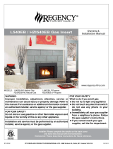
DIMENSIONS
Note: Oversize faceplate is 44" x 28" (1118 mm x 711mm)
Low Profi le Faceplate Dimensions
40-3/4 (1036mm)
35-15/16 (912mm)
27-15/16 (710mm)
14-7/8 (378mm)
22 (559mm)
23-15/16 (607mm)
10-7/8”
(276mm)
* Standard size shown, custom size also available.

4
FPI U31-2 Gas Fireplace Insert
TABLE OF CONTENTS
OPERATING INSTRUCTIONS
Operating Instructions .............................................27
Lighting Procedure ..................................................27
Shutdown Procedure ...............................................28
First Fire .............................................................28
Automatic Convection Fan Operation......................28
Normal Operating Sounds of Gas Appliances .........28
Copy of Lighting Instruction Plate ............................28
MAINTENANCE
Maintenance ............................................................29
Gold Plated Trim ...............................................29
Log Replacement ..............................................29
Glass Gasket ....................................................29
Door Glass Replacement ..................................30
Bay Glass Removal ..........................................30
Flush Glass Replacement .................................30
Fan Maintenance .....................................................30
Parts List .............................................................28
WARRANTY
Warranty .............................................................39
Unit Dimensions ........................................................3
Safety Label...............................................................5
INSTALLATION
For Your Safety ..........................................................8
Specifi cations ............................................................8
Installation into a Solid Fuel Fireplace .......................8
General Safety Information........................................8
Installation Checklist ..................................................9
Materials Required ...................................................9
Minimum Fireplace Clearances .................................9
Clearances to Combustibles......................................9
Conversion to Propane Kit.......................................10
Gas Connection .......................................................10
High Elevation .........................................................10
Draft Hood Connection ............................................10
Venting .............................................................11
Combustion & Ventilation ..................................11
Gas Pressure Test ...................................................11
Gas Insert Aeration System .....................................11
Test for Flue Spillage ...............................................11
Optional Brick Panel ...............................................12
Log Installation ........................................................13
Faceplate & Trim .....................................................16
Glass Front Installation
Standard Flush Door (1 panel) ..........................16
Flush Louvers ...................................................17
Optional Bay Front (3 panel) .............................17
Bay Louvers ......................................................17
Double Door Screen ................................................17
Wiring Diagram ........................................................18
Full Screen Front .....................................................19
Hampton Cast Faceplate Installation.......................21
Hampton Cast Faceplate Grill .................................22
Excalibur Surround ..................................................23
Low Profi le Faceplate Installation............................25
Optional Wall Thermostat ........................................27
Optional Remote Control ........................................27
Final Check .............................................................27

FPI U31-2 Gas Fireplace Insert
5
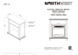
SAFETY LABEL
This is a copy of the labels that accompany each
U31-2 Gas Insert. We have printed a copy of the
contents here for your review. The safety label
is located on a plate inside the base of the unit
visible when the bottom louver is opened.
NOTE: FPI units are constantly being im-
proved. Check the label on the unit
and if there is a difference, the label
on the unit is the correct one.
DO NOT REMOVE THIS LABEL /
NE PAS ENLEVER CETTE ETIQUETTE
Serial No. / No de serie
218
218
Min. supply pressure 5" WC (1.25kPa)
Low Setting Man. pressure 1.1" WC (0.27kPa)
Max. Manifold pressure 3.8" WC (0.95kPa)
Orifice size 37 DMS (2.64mm)
Minimum input 14,500 Btu/h (4.25kW)
Altitude 0-2000ft (0-610m)
Maximum input 30,000 Btu/h (8.79kW)
Use Conversion Kit (Part #400-970)
Min. supply pressure 5" WC (1.25 kPa)
Low Setting Man. pressure 1.1" WC (0.27 kPa)
Max. Manifold pressure 3.8" WC (0.95 kPa)
Orifice size 40 DMS (2.49 mm)
Minimum input 13,000 Btu/h (3.81kW)
Altitude 2000-4500ft (610-1370m)
Maximum input 27,200 Btu/h (7.97kW)
908-786f
Mantel Clearances in Masonry
Fireplace Installation
NATURAL GAS FIREPLACE INSERT:
MODEL U31-NG2
PROPANE FIREPLACE INSERT:
MODEL U31-LP2
1
12" WC (2.99 kPa)
2.9" WC (0.72 kPa)
11" WC (2.74 kPa)
52 DMS (1.6mm)
13,700 Btu/h (4.01kW)
0-2000ft (0-610m)
27,500 Btu/h (8.057kW)
2" WC (2.99 kPa)
2.9" WC (0.72 kPa)
11" WC (2.74 kPa)
53 DMS (1.5mm)
12,400 Btu/h (3.63 kW)
2000-4500ft (610-1370m)
25,000 Btu/h (7.33 kW)
Use Conversion Kit (Part #400-971)
FPI Fireplace Products International Ltd.
Delta BC, CANADA
MADE IN CANADA / FABRIQUE AU CANADA
Model: U31-NG2
Model: U31-LP2
Factory Equipped For Altitude 0-2000ft. (0-610m)
Field Convertible For Altitude 2000-4500ft.(610-1370m)
Duplicate Serial number
K
L
A
B
O
N
P
Q
M
R
This appliance must be installed in accordance with local codes, if any; if none, follow the National Fuel Gas Code, ANSI Z223.1, or
Natural Gas and Propane Installation Code, CSA B149.1.
This appliance must be installed in accordance with the Standard CAN/CSA Z240 MH, Mobile Housing, in Canada, or with the Manufactured
Home Construction and Safety Standard, Title 24 CFR, Part 3280, in the United States, or when such a standard is not applicable,
ANSI/NCSBCS A225.1/NFPA 501A, Manufactured Home Installations Standard or ANSI A119.2 ou NFPA 501C Standard for Recreational
Vehicles
This appliance is only for use with the type of gas indicated on the rating plate and may be installed in an aftermarket, permanently located,
manufactured (mobile) home where not prohibited by local codes. See owner's manual for details.
WARNING.This fireplace has been converted for use with a gas fireplace insert only and cannot be used for burning wood or solid fuels unless
all original parts have been replaced, and the fireplace re-approved by the authority having jurisdiction.
Installer l'appareil selon les codes ou règlements locaux, ou, en l'absence de tels règlements, selon les codes d'installation ANSI Z223.1,
National Fuel Gas Code ou CSA-B149.1 en vigueur.
Installer l'appareil selon la norme CAN/CSA-Z240, Série MM, Maison mobiles ou CAN/CSA-Z240 VC, Véhicules de camping, ou la norme 24
CFR Part 3280, Manufactured Home Construction and Safety Standard. Si ces normes ne sont pas pertinentes, utilisez la norme
ANSI/NCSBCS A225.1/NFPA 501A, Manufactured Home Installations Standard, ou ANSI A119.2 ou NFPA 501C Standard for Recreational
Vehicles.
AVERTISSEMENT : Ce foyer a été converti pour utilisation avec un foyer au gaz encastrable et ne peut être utiliser pour brûler du bois ou
d'autres combustibles solides à moins que toutes les pièces d'origine aient été remplacées et que le foyer ait été approuvé de nouveau par
l'autorité compétente.
For use with glass doors certified with the appliance only
This vented gas fireplace heater is not for use with air filters. Ne pas utiliser de filtre à air avec ce foyer au gaz à évacuation.
Cet appareil doit être utilize uniquement avec le type de gaz indiqué sur la plaque signalétique. Cet appareil peut être installé dans une maison
préfabriquée ou mobile (É.-U. seulement) installée à demeure si les règlements locaux le permettent. Voir la notice de l'utilisateur pour plus de
renseignements. Cet appareil ne peut pas être utilisé avec d'autres gaz sauf si une trousse de conversion certifiée est fournie.
Pour utilisation uniquement avec les portes en verre certifiées avec l'appareil
Minimum Clearances to Combustibles from Insert
Side wall A 10"(255mm)
Ceiling B 47-1/2"(1205mm)
Alcove Width K 48"(1220mm)
Max. Alcove Depth L 36"(915mm)
NOTE: for Zero Clearance Kit clearances to
Combustibles. See manual for details.
Max. Mantel depth M 12"(305mm)
Mantel height N 17"(432mm)
Mantel depth O 3-1/2"(89mm)
Mantel height P 13"(330mm)
Floor Q 19-1/2"(495mm)
Mantel Clearances in Zero Clearance
Kit Installations
Max. Mantel depth M 12"(305mm)
Mantel height N 22"(432mm)
Listed:
Certified for/Certifi e pour:
Tested to:
4001172
CANADA and U.S.A.
CGA-2-17-M91, ANSI Z21.88a-2007 / CSA 2.33a-2007
VENTED GAS FIREPLACE HEATER
/ FOYER AU GAZ À ÉVACUATION
é
VENTED GAS FIREPLACE HEATER - NOT FOR USE WITH SOLID FUELS. /
NE PAS UTILISER AVEC DUCOMBUSTIBLE SOLIDE.
FOYER AU
GAZ À ÉVACUATION -
For the State of Massachusetts, installation and repair must be done by a plumber or gasfi tter licensed in the Commonwealth of
Massachusetts.
For the State of Massachusetts, fl exible connectors shall not exceed 36 inches in length.
For the State of Massachusetts, the appliances individual manual shut-off must be a t-handle type valve.
The State of Massachusetts requires the installation of a carbon monoxide alarm in accordance with NFPA 720 and a CO alarm
with battery back up in the same room where the gas appliance is installed.

6
FPI U31-2 Gas Fireplace Insert
REQUIREMENTS
5.08: Modifications to NFPA-54, Chapter 10
(2) Revise 10.8.3 by adding the following additional requirements:
(a) For all side wall horizontally vented gas fueled equipment installed in every dwelling, building or structure used in whole or in part for
residential purposes, including those owned or operated by the Commonwealth and where the side wall exhaust vent termination is less than
seven (7) feet above finished grade in the area of the venting, including but not limited to decks and porches, the following requirements shall
be satisfied:
1. INSTALLATION OF CARBON MONOXIDE DETECTORS. At the time of installation of the side wall horizontal vented gas fueled
equipment, the installing plumber or gasfitter shall observe that a hard wired carbon monoxide detector with an alarm and battery back-up is
installed on the floor level where the gas equipment is to be installed. In addition, the installing plumber or gasfitter shall observe that a battery
operated or hard wired carbon monoxide detector with an alarm is installed on each additional level of the dwelling, building or structure
served by the side wall horizontal vented gas fueled equipment. It shall be the responsibility of the property owner to secure the services of
qualified licensed professionals for the installation of hard wired carbon monoxide detectors
a. In the event that the side wall horizontally vented gas fueled equipment is installed in a crawl space or an attic, the hard wired carbon
monoxide detector with alarm and battery back-up may be installed on the next adjacent floor level.
b. In the event that the requirements of this subdivision can not be met at the time of completion of installation, the owner shall have a period of
thirty (30) days to comply with the above requirements; provided, however, that during said thirty (30) day period, a battery operated carbon
monoxide detector with an alarm shall be installed.
2. APPROVED CARBON MONOXIDE DETECTORS. Each carbon monoxide detector as required in accordance with the above provisions
shall comply with NFPA 720 and be ANSI/UL 2034 listed and IAS certified.
3. SIGNAGE. A metal or plastic identification plate shall be permanently mounted to the exterior of the building at a minimum height of eight
(8) feet above grade directly in line with the exhaust vent terminal for the horizontally vented gas fueled heating appliance or equipment. The
sign shall read, in print size no less than one-half (1/2) inch in size, "GAS VENT DIRECTLY BELOW. KEEP CLEAR OF ALL
OBSTRUCTIONS".
4. INSPECTION. The state or local gas inspector of the side wall horizontally vented gas fueled equipment shall not approve the installation
unless, upon inspection, the inspector observes carbon monoxide detectors and signage installed in accordance with the provisions of 248 CMR
5.08(2)(a)1 through 4.
(b) EXEMPTIONS: The following equipment is exempt from 248 CMR 5.08(2)(a)1 through 4:
1. The equipment listed in Chapter 10 entitled "Equipment Not Required To Be Vented" in the most current edition of NFPA 54 as adopted by
the Board; and
2. Product Approved side wall horizontally vented gas fueled equipment installed in a room or structure separate from the dwelling, building or
structure used in whole or in part for residential purposes.
(c) MANUFACTURER REQUIREMENTS - GAS EQUIPMENT VENTING SYSTEM PROVIDED. When the manufacturer of Product
Approved side wall horizontally vented gas equipment provides a venting system design or venting system components with the equipment, the
instructions provided by the manufacturer for installation of the equipment and the venting system shall include:
1. Detailed instructions for the installation of the venting system design or the venting system components; and
2. A complete parts list for the venting system design or venting system.
(d) MANUFACTURER REQUIREMENTS - GAS EQUIPMENT VENTING SYSTEM NOT PROVIDED. When the manufacturer of a
Product Approved side wall horizontally vented gas fueled equipment does not provide the parts for venting the flue gases, but identifies
"special venting systems", the following requirements shall be satisfied by the manufacturer:
1. The referenced "special venting system" instructions shall be included with the appliance or equipment installation instructions; and
2. The "special venting systems" shall be Product Approved by the Board, and the instructions for that system shall include a parts list and
detailed installation instructions.
(e) A copy of all installation instructions for all Product Approved side wall horizontally vented gas fueled equipment, all venting instructions,
all parts lists for venting instructions, and/or all venting design instructions shall remain with the appliance or equipment at the completion of
the installation.
MA Code - CO Detector
(for the State of Massachusetts only)

FPI U31-2 Gas Fireplace Insert
7
INSTALLATION
CLOTHING OR OTHER FLAMMABLE
MATERIAL SHOULD NOT BE PLACED
ON OR NEAR THE APPLIANCE.
CHILDREN AND ADULTS SHOULD BE
ALERTED TO THE HAZARDS OF HIGH
SURFACE TEMPERATURES, ESPE-
CIALLY THE FIREPLACE GLASS, AND
SHOULD STAY AWAY TO AVOID BURNS
OR CLOTHING IGNITION.
INSTALLATION AND REPAIR SHOULD
BE DONE BY AN AUTHORIZED
SERVICE PERSON. THE APPLIANCE
SHOULD BE INSPECTED BEFORE
USE AND AT LEAST ANNUALLY BY A
PROFESSIONAL SERVICE PERSON.
MORE FREQUENT CLEANING MAY
BE REQUIRED DUE TO EXCESSIVE
LINT FROM CARPETING, BEDDING
MATERIAL, ETC. IT IS IMPERATIVE THAT
CONTROL COMPARTMENTS, BURNERS
AND CIRCULATING AIR PASSAGEWAYS
OF THE APPLIANCE BE KEPT CLEAN.
DUE TO HIGH TEMPERATURES, THE
APPLIANCE SHOULD BE LOCATED
OUT OF TRAFFIC AND AWAY FROM
FURNITURE AND DRAPERIES.
WARNING: FAILURE TO INSTALL THIS
APPLIANCE CORRECTLY WILL VOID
YOUR WARRANTY AND MAY CAUSE A
SERIOUS HOUSE FIRE.
YOUNG CHILDREN SHOULD BE CARE-
FULLY SUPERVISED WHEN THEY ARE
IN THE SAME AREA AS THE APPLI-
ANCE. TODDLERS, YOUNG CHILDREN
AND OTHERS MAY BE SUSCEPTIBLE
TO ACCIDENTAL CONTACT BURNS. A
PHYSICAL BARRIERS IS RECOMMEND-
ED IF THERE ARE AT RISK INDIVIDUAL
IN THE HOUSE. TO RESTRICT ACCESS
TO A FIREPLACE OR STOVE, INSTALL
AN ADJUSTABLE SAFETY GATE TO
KEEP TODDLERS, YOUNG CHILDREN
AND OTHER AT RISK INDIVIDUALS OUT
OF THE ROOM AND AWAY FROM HOT
SURFACES.
FOR YOUR SAFETY
This appliance requires air for proper combustion.
Always provide adequate combustion and
ventilation air. Follow instructions and information
in CSA B149.1 (in Canada) or the National Fuel Gas
Code ANS Z223.1/NFPA (in the USA), regarding
requirements for combustion and ventilation air.

8
FPI U31-2 Gas Fireplace Insert
INSTALLATION
IMPORTANT:
SAVE THESE
INSTRUCTIONS
The FPI Gas Insert must be installed in ac-
cordance with these instructions. Carefully read
all the instructions in this manual fi rst. Consult
the building authority having jurisdiction to de-
termine the need for a permit prior to starting
the installation.
NOTE: Failure to follow the instructions
could cause a malfunction of the
heater which could result in death,
serious bodily injury, and/or prop-
erty damage. Failure to follow
these instructions may also void
your fi re insurance and/or warranty.
This appliance can be used with a
thermostat.
FOR YOUR SAFETY
This appliance requires air for proper combus-
tion. Always provide adequate combustion
and ventilation air. Follow instructions and
information in CAN/CGA B149 (in Canada) or
the National Fuel Gas Code ANSI Z223.1 (in the
USA), regarding requirements for combustion
and ventilation air.
SPECIFICATIONS
At pressures over 1/2 psig, the pipe to the unit
must be disconnected.
Gas Input Capacity:
Natural Gas 30,000 Btu/h
Propane 27,500 Btu/h
Min. Output (Fan Off)
Natural Gas 21,000 Btu/h
Propane 19,400 Btu/h
Max. Output (Fan On)
Natural Gas 22,000 Btu/h
Propane 20,500 Btu/h
Fuels: Approved for use with both natural
gas, and propane. Approved as is for use at
0' to 2,000'. With a fi eld installed conversion
kit 0' - 4,500'.
Electrical: 120V A.C. system.
Circulation Fan: Variable speed, 127 CFM.
Log Set: Ceramic fi bre, 7 per set.
Vent System: Minimum 4" B-Vent or listed
gas fuel vent liner.
GAS PRESSURE TESTING
The appliance must be isolated from the gas
supply piping system by closing its individual
manual shut off valve during any pressure
testing of the gas supply piping system at test
pressures equal to or less than 1/2 psig. (3.45
kPa). Disconnect piping from valve at test pres-
sures over 1/2 psig (3.45 kPa).
POLICY FOR SOLID
FUEL BURNING AND
FACTORY BUILT
FIREPLACES
The FPI U31-2 may be installed and vented into
any solid fuel fi replace that has been installed
in accordance with the National, Provincial and
local building codes and is constructed of non-
combustible materials.
1) Installer must mechanically attach the sup-
plied label to the inside of the fi rebox of the
fi replace into which the gas fi replace insert
is installed.
WARNING: This fi replace has been con-
verted for use with a gas fi replace insert
only and cannot be used for burning wood
or solid fuels unless all original parts have
been replaced, and the fi replace re-approved
by the authority having jurisdiction.
2) Do not cut any sheet-metal parts of the
fi replace, in which the gas fi replace insert
is to be installed.
3) If the factory-built fi replace has no gas access
hole(s) provided, an access hole of 1-1/2"
(37.5mm) or less may be drilled though
the lower sides or bottom of the fi rebox in
a proper workmanship like manner. This
access hole must be plugged with a non-
combustible insulation after the gas supply
line has been installed.
4) The fi replace fl ue damper can be fully
blocked open or removed for installation of
the gas fi replace insert.
5) The fi replace and fi replace chimney must
be clean and in good working order and
constructed of non-combustible materials.
6) The chimney cleanouts must fi t properly.
7) Refractory (fi rebricks), glass doors, screen
rails, screen mesh and log grates can be
removed from the fi replace before installing
the gas fi replace insert.
8) Smoke shelves, shields and baffl es may be
removed if attached by mechanical fasten-
ers. If any part is removed it must not weaken
the structural integrity of the factory built.
9) Trim panels or surrounds shall not seal
ventilation openings in the fi replace.
BEFORE YOU START
Safe installation and operation of this appliance
requires common sense, however, we are
required by the Canadian Safety Standards
and ANSI Standards to make you aware of
the following:
General Safety Information
1) The appliance installation must conform
with local codes or in the absence of local
codes, with CAN/CGA B149 (in Canada)
or the National Fuel Gas Code ANSI
Z223.1. This appliance should be installed
by a qualifi ed gas fi tter technician only.
2) Installation and repair should be done
by a qualifi ed service person.
3) The appliance should be inspected before
use and at least annually by a professional
service person. More frequent cleaning
may be required due to excessive lint from
carpeting, bedding material, animal hair, etc.
It is imperative that control compartments,
burners and circulating air passageways of
the appliance be kept clean.
4) See general construction and assembly
instructions. This appliance may only be
installed in a vented, noncombustible fi re-
place.
5) This appliance is Listed for bedroom instal-
lations. In Canada room heaters must be
installed with a Listed Millivolt Thermostat.
Some areas may have further requirements,
check local codes before installation.
6) This unit is not approved for installation into
a mobile home.
7) Always connect this insert to a vent sys-
tem venting to the outside of the building
envelope. Never vent to another room or
inside a building. Make sure that the vent
is properly sized and is of adequate height
to provide the proper draft.
8) Inspect the venting system annually for
blockage and any signs of deterioration.
9) Any glass removed for servicing must be
replaced prior to operating the appliance.
10) To prevent injury, do not allow anyone who
is unfamiliar with the operation to use the
fi replace.

FPI U31-2 Gas Fireplace Insert
9
INSTALLATION
NOTE: Mantel clearances for Installation into
a Zero Clearance Kit are different. Please
refer to the Zero Clearance Kit Manual for
details.
MINIMUM FIREPLACE
DIMENSIONS
The minimum fi replace dimensions for the FPI
gas fi replace insert are shown in the following
diagrams:
Combustible Mantel Clearances
with Bay & Flush Louvers in
Masonry Installation
8-1/8”
Low prole
Note: A non-combustible mantel may be
installed
at a lower
height if the
framing is
made of
metal studs
covered
with a non-
combusti-
ble board.
11) Failure to position the parts in accordance
with the diagrams in this manual or failure
to use only parts specifi cally approved with
this appliance may result in property damage
or personal injury.
12) Due to high temperatures, the appliance
should be located out of high traffi c areas
and away from furniture and draperies.
Children and adults should be alerted to
the hazards of high surface temperatures,
especially the fi replace glass and gold
trims, and should stay away to avoid burns
or clothing ignition. Young children should
be carefully supervised when they are in
the same room as the appliance. Clothing
or other fl ammable material should not be
placed on or near the appliance.
INSTALLATION
CHECKLIST
The FPI Gas Insert is installed as listed be-
low.
1) Unit Location - check Clearances to Com-
bustibles on page 6.
2) Make the gas connections (see page 7).
Convert to Propane Gas if necessary, page
7.
3) Install the fl ue or liner to the sliding draft
hood. See page 8.
4) Install Venting, page 8. Slide the unit into the
fi replace. Attach draft hood to the insert.
5) Test gas pressure, page 8. Check aeration,
page 8.
6) Test for fl ue spillage, page 8.
7) Install the optional brick panels. See page
9.
8) Install the log set. See page 9.
9) Assemble and install the faceplate and trim.
See page 11.
10) Install the glass front and optional Bay Front.
See pages 11 & 12.
11) Install both louvers. See page 12.
12) Install Optional Double Screen Door. See
page 12
13) Install Optional Remote Control and Optional
Wall Thermostat, page 20.
14) Final check: Before leaving this unit with the
customer, the installer must ensure that the
appliance is fi ring correctly. This includes:
a) Clocking the appliance to ensure the
correct fi ring rate.
b) Adjusting the primary air, if required,
to ensure that the fl ame does not
carbon. See page 10.
c) Ensuring that the appliance is venting
correctly. See page 9.
MATERIALS REQUIRED
No electrical power supply is required for the gas
control to operate. A 120 Volt AC power cord is
hooked up to the fan. Plug the 3 wire cord into
a suitable receptacle. Do not cut the ground
terminal off under any circumstances. When
connected with 120 volts, the appliance must be
electrically grounded in accordance with local
codes, or in the absence of local codes, with the
current Canadian Electrical Code CSA C22.1 (in
Canada) or with the current National Electrical
Code ANSI/NFPA 70-1987 (in U.S.A.).
NOTE: This unit is equipped with a heat sen-
sor thermodisc which will prevent the
blower from operating until the unit
reaches the correct temperature.
CLEARANCES TO
COMBUSTIBLES
From Unit
Sides A 10" / 255 mm
Ceiling B 47.5" / 1205 mm
Mantle C See mantle
clearances
From Standard Surround (26" x 40")
Sides D 4" / 100 mm
Ceiling E 41.5" / 1055 mm
Max. Mantel Depth G 12" / 305 mm
Min. Alcove Width K 48" / 1220 mm
Max. Alcove Depth L 36" / 915 mm
* No Hearth Required
Note: If you are installing the Molded Faceplate
or Excalibur Surround, the minimum fi replace
dimensions are as follows:
Width (at front): 29" (737mm)
Depth: 16" (406mm)
Emissions from burning wood or gas could
contain chemicals known to the State of Cali-
fornia to cause cancer, birth defects or other
reproductive harm.

10
FPI U31-2 Gas Fireplace Insert
INSTALLATION
THIS CONVERSION MUST BE DONE BY A QUALIFIED GAS
FITTER IF IN DOUBT DO NOT DO THIS CONVERSION !!
Conversion Kit from Natural Gas to Propane
Model #402-969 for: U31-NG2 Units
1) Turn the unit off and allow it to cool to room
temperature.
2) Unplug or disconnect power source to
stove.
3) Remove glass front (see manual).
4) Remove logs and brick panels (if in-
stalled).
5) Remove the Grate by removing the screws
on each side of the grate.
Remove the 2 screws holding
the grate in position.
Remove the 2 screws,
push Burner Tray to the left, and lift off.
6) Remove the Burner Tray by removing the
screws on each side of the tray. Push the
tray to the left and lift up.
7) Remove burner orifi ce with 1/2" wrench and
replace with the #52 orifi ce in the Kit.
Diagram 1
8) Remove regulator from valve and replace
with Propane regulator. See diagram 1.
Burner
Orifi ce
9) Pull off the pilot cap to expose the pilot
orifi ce.
10) Unscrew the pilot orifi ce with the allen key
and replace with the LP pilot orifi ce in the
kit.
11) Replace Burner Tray and reverse steps 5)
to 1).
12) Adjust the burner aeration setting to 1/8"
to 3/16" as required for the best fl ame pic-
ture.
GAS CONNECTION
3) Locate the center point where the vent will
pass through the chimney above the appli-
ance. Move the appliance into the exact
location where it is to be installed. Ensure
that the Insert is level.
4) The installer must provide a valve with a
plugged tapping, accessible for test gauge
connection, immediately upstream of the
gas supply connection to the appliance.
HIGH ELEVATION
This unit is approved in Canada for altitude 0 to
2000 ft. with the orifi ce supplied. For 0' - 4500'
use the optional fi eld conversion kit (Part #400-
970 for Natural Gas units and Part #400-971 for
Propane units). In USA refer to ANSI Z223.1-
1988, Appendix F, for re-sizing orifi ce.
DRAFT HOOD
CONNECTION
1) Attach the vent to the fl ue collar on the
detachable draft hood. The fl ue collar of
the appliance will fi t inside a standard vent
and may be fastened directly to the vent by
sheet metal screw. Diagram 1.
2) Before pushing the appliance into position
inside the fi replace, align the draft hood
with the guides on the insert top and push
forward. While pushing the unit back into
place keep pulling the draft hood forward
until the screw hole in the spill tube aligns
GAS CONNECTION WARNING:
Only persons licensed to work
with gas piping may make the
necessary gas connections to this
appliance.
1) If the appliance is to be installed into an
existing chimney system, thoroughly clean
the masonry or factory built fi replace.
2) The appliance is provided with an opening
on the left hand side of the control com-
partment. A 1/2" gas supply pipe must be
brought near this inlet hole. (See Diagram
3 on page 11).

FPI U31-2 Gas Fireplace Insert
11
INSTALLATION
TEST FOR FLUE
SPILLAGE
A " spillage" test must be made before the
installed unit is left with the customer. Follow
the procedure below:
1) Start all exhaust fans in the home and then
close all external doors and windows in the
house.
2) Light the unit and set controls to maximum.
Turn fan off.
The manifold pressure is controlled by a regulator
built into the gas control, and should be checked
at the pressure test point. The pressure check
should be carried out with the unit burning and the
setting should be within the limits specifi ed.
GAS INSERT AERATION
SYSTEM
The aeration adjustment rod is attached to the
air shutter which is located just above the orifi ce
bracket. The rod is used to adjust the aeration
on the main burner without having to take the
appliance apart.
The burner aeration is factory set but may need
adjusting due to either the local gas supply, air
supply or altitude.
Natural Gas: 1/8" (3.2mm) open
Propane: 3/16" (4.8mm) open
Note: Any damage due to carboning result-
ing from improperly setting the aera-
tion controls is NOT covered under
warranty.
Note: Aeration Adjustment should only
be performed by an authorized FPI
Installer at the time of installation or
service.
with the screw hole in the top of the fi rebox.
The screw is secured through the inside top
of the fi rebox into the bottom of the spill tube.
(If screw holes do not line up then draft hood
is not positioned correctly.)
NOTE: fi nal gas connection should be
after unit is in place to avoid damage
to line when pushing the unit into
position.
VENTING
Diagram 1
Diagram 2
THE APPLIANCE MUST NOT BE
CONNECTED TO A CHIMNEY FLUE
SERVING A SEPARATE SOLID
FUEL BURNING APPLIANCE.
This appliance is designed to attach to a 4" diam-
eter type B-Vent or listed gas fuel type vent liner
running the full length of the chimney. A minimum
fl ue height of 12 feet is recommended. B-Vent
must be supported by a vent support - supplied
by vent manufacturer. See chart on this page
for minimum distances from roof.
TheFPI Insert incorporates its own internal
draft hood, so no additional external draft hood
is required.
Periodically check that the vent is unrestricted
and an adequate draft is present when the unit
is in operation. (See page 8 for spillage test.)
Before installing vent system ensure that the
damper plate is open and secure to prevent
the damper plate from falling down and crush-
ing the liner.
WARNING: Operation of this ap-
pliance when not connected to a
properly installed and maintained
venting system or tampering with
the blocked vent shutoff system
can result in carbon monoxide (CO)
poisoning and possible death.
Combustion and Ventilation Air
WARNING: This appliance needs
fresh air for safe operation and must
be installed with provisions for ad-
equate combustion and ventilation
air available to the room in which it
is to be operating.
Follow CAN/CGA B149 (in Canada) or ANSI
Z223.1 (in the USA) requirements, and any
local codes or regulations of the enforcing
authority.
Air for combustion is drawn in through the front
of the unit, therefore, the front of the unit must
be kept clear of any obstructions.
GAS PRESSURE TEST
The unit is preset to give the correct gas input
at the specifi ed manifold pressures shown on
the label. The maximum gas manifold pressure
is:
Natural Gas 3.8" w.c.
Propane 11.0" w.c.

12
FPI U31-2 Gas Fireplace Insert
INSTALLATION
Diagram 1
3) After fi ve minutes, test that there is a “pull” on
the fl ue by placing a smoke match, cigarette
or similar device which gives off smoke,
in front of the spill tube. To ensure a valid
test, place a scrap piece of sheet metal (or
other noncombustible material) between
the spill tube and the upper louver, this will
prevent the natural convection of the unit
from interfering with the test. See diagram
1.
Diagram 1
Diagram 2
Diagram 3
The smoke should be drawn into the spill tube.
If the smoke is still not drawn into the spill tube,
turn the unit off and check for the cause of the
lack of draft. If necessary, seek expert advice.
For wind turbulent sites, a wind cap may remedy
the problem.
Note: The thermally activated safety switch
will sense the change in temperature and shut
down the gas valve in the event of a severe
downdraft or a blocked or disconnected
vent. The switch acts as a safety shut-off to
prevent a build-up of carbon monoxide. If the
fl ue is blocked or has no "draw", the switch
will automatically shut off the supply of gas
within 5 - 10 minutes. Tampering with the
switch can result in carbon monoxide (CO)
poisoning and possible death.
If the heater turns off because of lack of draft
during the spillage test, check for the cause
and if necessary, seek expert advice.
The thermally actuated safety switch will
automatically reset after it has cooled off.
The switch will continue to cycle until the
draft problem is corrected. DO NOT BYPASS
OR DISCONNECT THIS SWITCH.
OPTIONAL
BRICK PANEL
1) Unwrap the brick pattern panels from the
protective wrapping.
2) Remove the glass front if it is already in-
stalled.
3) Put the rear brick panel fl at against the back
of the unit.
4) Before installing the side brick panels, loosen
the screws for the brick tabs enough so that
you can slide the brick tabs on to the screws
easily but that the tabs are secure. For the
location of the side brick tab screws see
diagram 1.
5) Remove the brick tabs and slide the side
brick panels into position. See diagram 3.
Install the brick tabs. See diagram 2.

FPI U31-2 Gas Fireplace Insert
13
INSTALLATION
LOG SET INSTALLATION
Read the instructions below carefully and refer to the diagrams. If logs are broken do not use the unit until
they are replaced. Broken logs can interfere with the pilot operation.
The gas log kit contains the following:
a) 02-43 Rear Log
b) 02-45 Front Right Log
c) 02-56 Middle Left Log
d) 02-46 Left Top Log
e) 02-47 Center Log
f) 02-48 Middle Right Log
g) 02-44 Front Left Log
h) 902-154 Embers
i) 902-153 Rockwool
j) 902-179/P Vermiculite
k) 946-669 Platinum Embers
(supplied with packaged manual)
Note: Install Optional Brick Panels prior to installing logs.
1) Carefully remove the logs from the box and unwrap
them. The logs are fragile, handle with care - do not
force into position.
2) Sprinkle the vermiculite around the fi rebox base. Take
some of the embers (approx. 1/3 of the bag) and
sprinkle over the vermiculite.
3) Place Rear Log A)02-43 on the two pins on the rear
log support.
Vermiculite
and embers
Vermiculite
and embers
Vermiculite
and embers
Pins on Rear Log Support
4) Place Front Right Log B)02-45 on the two pins as
shown.
A)02-43
B)02-45
The "02" refer numbers (i.e. 02-43) are
molded into the rear of each log.

14
FPI U31-2 Gas Fireplace Insert
INSTALLATION
Logs D)02-46 and E)02-47 in position.
6) Place the Left Top Log D)02-46 on the pin on Log
C)02-56 and on top of the cutout on Log A)02-43.
7) Place the notch in Center Log E)02-47 over Log B)02-
45 and across the cutout on Log A)02-43.
Cutout
Pin
Cutout
Notch
8) Position notch in Front Right Log F)02-48 on Log
E)02-47 and push the bottom right edge against the
bracket on the burner tray and the front edge of the
rear burner.
Notch
Bracket
D)02-46
E)02-47
F)02-48
C)02-56
A)02-43
B)02-45
A)02-43
B)02-45
E)02-47
Logs A)02-43, C)02-56, and B)02-45 in position
C)02-56
5) Place the Middle Left Log C)02-56 on the two pins as
shown.

FPI U31-2 Gas Fireplace Insert
15
INSTALLATION
10) Place the embers and Rockwool on the exposed front
burner tray.
9) Place Front Left Log G)02-44 onto the 2 front pins as
shown.
G)02-44
F)02-48
B)02-45
Bracket
A)02-43
Front edge of
rear burner
The bottom right edge of Log F)02-48 must sit snugly against
the bracket and the front edge of the rear burner.
Side View
11) Separate platinum embers and place on and around
the embers and rockwool on the burner tray. Avoid
stacking platinum embers.
12) Test fi re to ensure proper light off (make sure fl ame
fl ows smoothly from one end of burner to the other. If
there is any fl ame hesitation, check that area for any
blockage of the burner port.
The "02" refer numbers (i.e. 02-43) are
molded into the rear of each log.
A) 02-43 D) 02-46
G) 02-48
C) 02-44
B) 02-56
F) 02-47 E) 02-45

16
FPI U31-2 Gas Fireplace Insert
INSTALLATION
Diagram 4
Diagram 5
Rear View: Trim Assembly
Diagram 2
Diagram 3
Rear View: Faceplate Assembly
Diagram 1
FACEPLATE & TRIM
INSTALLATION
1) Lay the faceplate panels fl at, face down on
something soft so they don't scratch.
2) Take the top faceplate and align the holes in
it with the holes in the side panels. Using the
screws provided, attach from the top of the
panel (the holes in the top panel are slightly
larger than the holes in the side panel to
facilitate easier installation). Diagram 1.
Hint: Don't tighten the screws down com-
pletely at this point, continue on with steps
3 and 4 and do a trial fi t to the unit. Make
any necessary adjustments and when it fi ts
properly then tighten down the screws.
Hearth Trim Option: Hearth Trim is an
option that can be used to fi nish off the
installation when the bottom of the fi replace
is higher than the hearth or to raise the fi re-
place. Attach the Hearth Trim to the bottom
of the faceplate side panels with the screws
provided. See Diagram 1.
3) Using the connectors provided, join the left
side trim (with the ON/OFF switch) to the
top trim. Diagram 2. Connect the right side
trim to the top trim.
4) Place the trim on the assembled faceplate
panels, aligning the wire connections from
the switches with the notch on the left side
panel.
5) Connect the fan switch wires by taking the
black and red wires with the male ends (in
the grey harness) and connect them with
the wire connectors from the fan speed
control.
6) Connect the ON/OFF switch wires by taking
the black and red wires with the female ends
and connect them to the ON/OFF switch.
7) Tuck the wires into the faceplate to keep
them away from the insert using the clip
provided. Attach the clip to the rear of the
faceplate to ensure that the wires do not
touch the side of the unit. Diagram 3.
8) The power cord should be run behind the
faceplate panel.
9) Attach the brass trim to the faceplate by
drilling a 1/8" hole through into the faceplate
using the hole in the trim as a guide. Fasten
the trim to the faceplate panels using the
plated screws. Diagram 4.
10) Attach the faceplate panels to the insert
body using the 4 remaining black screws.
Diagram 5.
11) Push the Regency logo plate into the two
holes in the bottom left corner of the face-
plate.
FLUSH FRONT
INSTALLATION
1) Install Logs before going on to the next
step. See the Log Installation instruction
sheet or page 9.
2) Install the bottom glass trim by hooking the
trim into the lip on the fi rebox base. The trim
will not fi t into place if the glass is installed
fi rst.

FPI U31-2 Gas Fireplace Insert
17
INSTALLATION
BAY FRONT
INSTALLATION
1) Place the bay door onto the 2 pins on the
top of the unit.
2) Install bottom louver by sliding the two
bracket clips into the brackets located
underneath the bay door and secure with
2 screws into the bracket on the bottom of
the Bay Front as per diagram above.
3) Slide the valve extension knobs onto the
valve knobs. match the correct ext. knob
with the valve knob.
BAY LOUVERS
1) Install top louver by sliding the two bracket
clips into the brackets located on top of the
bay door. See below. The fi tted louver leaves
a small gap between faceplate bottom and
louver top.
FLUSH LOUVERS
3) Place the bottom of the fl ush glass behind
the bottom glass trim.
4) Secure the glass with the two glass clips at
the top corners of the glass. Secure glass
clips with the screws provided. Do not over
tighten as this could break the glass.
5) Slide in the top glass trim under the spring
clips.
2) Position 2 magnets on the back of each trim
piece close to the ends. Place the top and
bottom trim pieces on the bay front.
3) Install top and bottom louvers.
Note: The top and bottom trim pieces are
different, check diagrams above and
below.
DOUBLE DOOR
SCREEN
1) Pull out the
top louver
and the top
glass trim.
2) Loosen the
screws so
the glass
clips can
be turned
aside and
the flush
glass re-
moved.
1) The Top Louver is held in place by friction
fi t, if the Louver needs to be adjusted; bend
the bracket out as shown in the diagram.
2) Install the Spring Hinges on the left and right
side of the bottom of the Firebox using 2
screws per hinge.
Bottom Louver
Hinge
Location
3) Place the Bottom Louver near the hinge. Flip
hinge over the Bottom Louver and secure
using 3 screws.

18
FPI U31-2 Gas Fireplace Insert
INSTALLATION
WIRING DIAGRAM
CAUTION: Label all wires prior
to disconnection when servic-
ing controls. Wiring errors can
cause improper and dangerous
operation.
WARNING: Electrical Grounding Instructions
This appliance is equipped with a three pronged (grounding) plug for your protection against shock hazard and should
be plugged directly into a properly grounded three-prong receptacle. Do not cut or remove the grounding prong from
this plug.
This heater does not require a 120V A.C. sup-
ply for operation. In case of a power failure, the
burner switch and the optional remote control/
thermostat will continue to operate. However,
a 120V A.C. power supply is needed for the
fan/blower operation.
Caution: Ensure that the wires do
not touch any hot surfaces and are
away from sharp edges.
Slots
Push Screen
Door down
fi rmly
to lock into
place.
3) Open Bottom Louvers.
4) Remove the bottom glass trim.
Discard both top & bottom glass trim.
5) Replace the glass and secure with the two
glass clips. Do not over tighten as this could
break the glass.
Make sure the glass is centered.
6) Insert side hooks on the double screen
door into the 4 slots between the faceplate
and the glass and lower assembly into the
locking position. Push down fi rmly with both
hands to lock into place.
Side Hook
Insert Screen Door
hooks into the 4
slots between the
faceplate and the
fl ush door.

FPI U31-2 Gas Fireplace Insert
19
INSTALLATION
FULL SCREEN FRONT
1) Hold the full screen door up against the unit in order to make the
following wire connections.
Pull the ON/OFF connector wires from the fi rebox and connect them
to the switch.
Connect the fan switch wires with the wire connectors from the fan
speed control. Place clips over wires and tuck into side trim.
2) Lift unit up slightly and push down on the corners of the Bottom Trim
Bracket and slide under unit. Unit should touch tabs on Bottom Trim
Bracket.
Bottom Trim Bracket
Push in Corners
3) Completely secure the full screen door to the unit by securing 4
screws to the Left and Right Side Trims.
.
NOTE: When mounting the full screen door to the unit, the inside
fl ange of the side trims are to fi t over the inner side of the unit fl ange
and NOT next to the outer side of the unit fl ange.
Inside fl ange of Side Trim goes over
the inner side of the unit fl ange.

20
FPI U31-2 Gas Fireplace Insert
INSTALLATION
5) Place Bottom Frame near hinge. Flip hinge over Bottom Frame and
secure with 3 screws.
4) Install Spring Hinges on the Left and Right Side of the bottom of the
fi rebox using 2 screws per hinge.
6) The Top Frame is held in place by friction fi t, if the frame needs to
be adjusted; bend the bracket accordingly.
Top Frame
Hinge
Screen Door
7) Install the Left and Right Side Screen Doors in the fully open position
by placing over top of the hinges on the full screen door.
8) Close screen doors.
NOTE: If you fi nd that the doors do not align properly, adjust the
hinges on the door(s) by loosening them and adjust accordingly.
Bottom Frame
Hinge Location
/