YSI 6000UPG Multiparameter Water Quality Monitor Owner's manual
- Category
- Measuring, testing & control
- Type
- Owner's manual

6000UPG
Multi-Parameter
Water Quality Monitor
Instruction Manual
YSI Incorporated
1725 Brannum Lane
Yellow Springs, OH 45387
(800) 765-4974 (513) 767-7241
Fax (513) 767-9353
â

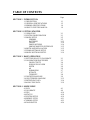
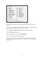
TABLE OF CONTENTS
Page
SECTION 1 INTRODUCTION
1.1 DESCRIPTION 1-1
1.2 GENERAL SPECIFICATIONS 1-3
1.3 SENSOR SPECIFICATIONS 1-4
1.4 HOW TO USE THIS MANUAL 1-6
SECTION 2 GETTING STARTED
2.1 UNPACKING 2-1
2.2 SYSTEM CONFIGURATION 2-1
2.3 SONDE SETUP 2-5
SENSORS 2-5
BATTERIES 2-12
CABLES 2-14
POWER OPTIONS 2-14
SONDE/COMPUTER INTERFACE 2-15
2.4 SOFTWARE INSTALLATION 2-15
2.5 PC6000 SOFTWARE SETUP 2-16
2.6 SONDE SOFTWARE SETUP 2-19
SECTION 3 BASIC OPERATION
3.1 GETTING READY TO CALIBRATE 3-1
3.2 CALIBRATION PROCEDURES 3-2
CONDUCTIVITY 3-4
DISSOLVED OXYGEN 3-5
DEPTH 3-6
pH 3-6
AMMONIUM 3-7
NITRATE 3-7
TURBIDITY 3-8
3.3 DISCRETE SAMPLING 3-9
3.4 UNATTENDED SAMPLING 3-12
3.5 RETRIEVING DATA 3-14
3.6 ANALYZING DATA 3-16
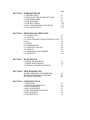
SECTION 4 SONDE MENU
4.1 RUN 4-1
4.2 CALIBRATE 4-9
4.3 FILE 4-14
4.4 STATUS 4-18
4.5 SYSTEM SETUP 4-19
4.6 REPORT SETUP 4-21
4.7 SENSOR SETUP 4-22
4.8 DIAGNOSTICS 4-24

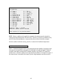
Page
SECTION 5 PC6000 SOFTWARE
5.1 INTRODUCTION 5-1
5.2 INSTALLING THE PC6000 SOFTWARE 5-1
5.3 THE SONDE MENU 5-3
5.4 THE FILE MENU 5-3
5.5 THE SETUP MENU 5-20
5.6 DATA CAPTURE/REAL-TIME SETUP 5-23
5.7 ADVANCED SETUP 5-25
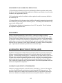
SECTION 6 PRINCIPLES OF OPERATION
6.1 CONDUCTIVITY 6-1
6.2 SALINITY 6-2
6.3 OXIDATION REDUCTION POTENTIAL (ORP) 6-2
6.4 pH 6-4
6.5 DEPTH 6-5
6.6 TEMPERATURE 6-6
6.7 DISSOLVED OXYGEN 6-6
6.8 NITRATE 6-9
6.9 AMMONIUM AND AMMONIA 6-11
6.10 TURBIDITY 6-14
SECTION 7 MAINTENANCE
7.1 SONDE MAINTENANCE 7-1
7.2 PROBE MAINTENANCE 7-4
7.3 GENERAL MAINTENANCE NOTE 7-7
SECTION 8 TROUBLESHOOTING
SONDE COMMUNICATION PROBLEMS 8-2
SENSOR PERFORMANCE PROBLEMS 8-2
SOFTWARE PROBLEMS 8-5
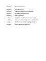
SECTION 9 COMMUNICATION
9.1 OVERVIEW 9-1
9.2 HARDWARE INTERFACE 9-1
9.3 SDI-12 INTERFACE 9-2
9.4 RS-232 INTERFACE 9-7
9.5 FILE TRANSFER PROTOCOLS 9-7
9.6 FILE FORMATS 9-8
9.7 MODEM SETUP 9-9

APPENDIX A HEALTH AND SAFETY
APPENDIX B REQUIRED NOTICE
APPENDIX C WARRANTY AND SERVICE INFORMATION
APPENDIX D ACCESSORIES AND REAGENTS
APPENDIX E APPLICATION NOTE
APPENDIX F SOLUBILITY AND PRESSURE/ALTITUDE TABLES
APPENDIX G SENSOR AND SONDE STORAGE RECOMMENDATIONS
APPENDIX H TURBIDITY MEASUREMENTS WITH THE 6820
APPENDIX I SYSTEM ERRORS AND WARNINGS

1-1
1. INTRODUCTION
1.1 DESCRIPTION
The 6000UPG Environmental Monitoring System is a multiparameter, water quality measurement,
and data logging system. It is intended for use in research, assessment, and regulatory compliance
applications.
Measurement parameters include:
• Dissolved Oxygen
• Conductivity
• Specific Conductance
• Salinity
• Total Dissolved Solids
• Resistivity
• Temperature
• pH
• ORP
• Depth
• Level
• Ammonium/Ammonia
• Nitrate
• Turbidity
The 6000
UPG is ideal for profiling and monitoring water conditions in lakes, rivers, wetlands,
estuaries, coastal waters, and monitoring wells. It can be left unattended for weeks at a time with
measurement parameters sampled at a user-defined setup interval and data securely saved in the
unit's internal memory. The 6000
UPG can be used 500 feet (152 meters) below the surface of the
water, or in as little as a few inches of water. The fast sensor response of the 6000
UPG and its
built-in data logging make it ideal for vertical profiling. Its small size means it can fit down 4 inch
(10.2 cm) diameter monitoring wells.
A patented Rapid Pulse Dissolved Oxygen Sensor exhibits low stirring dependence and, therefore
provides accurate results without an expensive and bulky stirrer. Because stirring is not required,
battery life is extended. In addition, because of the nature of the technology, sensor drift caused by
passive fouling is minimized.
The Model 6000
UPG is designed to house 4 field-replaceable probes (6 sensors) and the option to
add a depth sensor module to the sonde body. If necessary, the dissolved oxygen-conductivity-
temperature, pH, ammonium, nitrate ORP, and turbidity sensors are quickly replaced in the field.
The 6000
UPG communicates with an ASCII terminal or a computer with a terminal emulation
program. Every 6000
UPG comes with IBM-compatible PC-based software for simple and convenient
setup and data handling. Reports and plots are automatically generated and their presentation easily
customized. Data is easily exported to any spreadsheet program for more sophisticated data
processing.

1-2
The RS-232C and SDI-12 interfaces provide maximum versatility for system networking and real
time data collection. Several 6000
UPG units are easily installed in a vertical string providing
valuable water quality data at a variety of depths. For real time results, the 6000
UPG can interface to
radio telemetry systems and satellite, telephone, or cellular phone data collection platforms. In
addition, the unit can be used with our 610-D or 610-DM display/logger for profiling or spot
sampling applications. The 6000
UPG is equipped with sensor and communication circuitry to
eliminate ground loop interference.
When the 6000
UPG is factory configured for internal power, it operates using eight C-size alkaline
batteries. These batteries are easily replaced in the field, without disassembly of the unit. The
minimal power requirements of the Rapid Pulse Dissolved Oxygen Sensor combined with
state-of-the-art electronic circuits and software can provide up to 90 days of battery life during
normal use, depending on the activated sensor configuration.
The 6000
UPG comes standard with 256 kilobytes of memory; this is enough to store 150,000
individual parameter readings for a typical deployment.
Optional cables are available for interfacing the 6000
UPG with a computer, terminal, or
display/logger. These cables are waterproof at the sonde connection and can be used in the lab or
field.
See Appendix D for a complete list of accessories and calibration reagents.

1-3
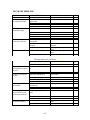
1.2 GENERAL SPECIFICATIONS
See also Section 1.3 Sensor Specifications.
Operating Environment
Medium: fresh, sea, or polluted water
Temperature: -5 to +45 °C
Depth: 0 to 500 feet (152 meters)
Storage Temperature: -40 to +60 °C
Material: PVC, Stainless Steel
Dimensions
Diameter: 3.5 inches (8.9 centimeters)
Length: 19.5 inches (49.5 centimeters)
Weight: 6.5 pounds (3.0 kilograms) , with batteries
Computer Interface
RS-232C
SDI-12
Software
PC6000
IBM PC compatible computer, 3 1/2 or 5 1/4 inch, high or low density disk drive.
Minimum RAM requirement: 256 kilobytes
Optional graphic adapter for plotting
Ecowatch for Windows (optional)
IBM PC compatible computer with 3 1/2 inch disk drive and with a 386 processor (or
better) running Windows version 3.1 (or later).
Minimum RAM requirement: 4 megabytes
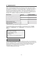
Internal logging memory size (typical deployment)
256 kilobytes (150,000 individual parameter readings)
512 kilobytes (300,000 individual parameter readings)
Power (two options)
12 VDC (8 C-size Alkaline Batteries)
External 12 VDC
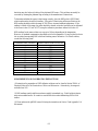
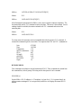
Battery Life
120 days without dissolved oxygen and turbidity sensor activation
90 days without turbidity sensor activation
45 days with dissolved oxygen and turbidity sensor activation

1-4
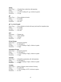
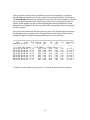
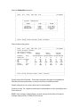
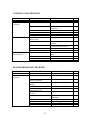
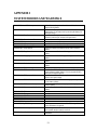
1.3 SENSOR SPECIFICATIONS
The following are typical performance specifications for each sensor.
Depth - Deep
Sensor Type...........Stainless steel strain gauge
Range.....................0 to 500 ft (152 m)
Accuracy................+/- 1 ft (0.3 m)
Resolution..............0.001 ft (0.001 m)
Depth - Medium
Sensor Type...........Stainless steel strain gauge
Range.....................0 to 200 ft (61 m)
Accuracy................+/- 0.4 ft (0.12 m)
Resolution..............0.001 ft (0.001 m)
Depth - Shallow
Sensor Type..............Stainless steel strain gauge
Range........................0-30 ft (9.1 m)
Accuracy ................ +/- 0.06 ft (0.018 m)
Range........................0.001 ft (0.001 m)
Temperature
Sensor Type...........Thermistor
Range.....................-5 to 45 °C
Accuracy................+/- 0.15 °C (optional configuration at +/- 0.05 °C)
Resolution..............0.01 °C
Dissolved Oxygen % saturation
Sensor Type...........Rapid Pulse - Clark-type, polarographic
Range.....................0 to 200 % air saturation
Accuracy................+/- 2 % air saturation
Resolution..............0.1 % air saturation
Dissolved Oxygen mg/L (Calculated from % air saturation, temperature and salinity)
Sensor Type............ Rapid Pulse - Clark-type, polarographic
Range.....................0 to 20 mg/L
Accuracy................+/- 0.2 mg/L
Resolution..............0.01 mg/L
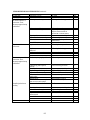
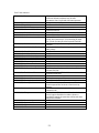
Conductivity
*
Sensor Type...........4 electrode cell with autoranging
Range.....................0 to 100 mS/cm
Accuracy................+/- 0.5% of reading + 0.001 mS/cm
Resolution..............0.01 mS/cm or 1 uS/cm
* Report outputs of specific conductance (conductivity corrected to 25 C), resistivity, and total dissolved
solids are also provided. These values are automatically calculated from conductivity according to
algorithms found in Standard Methods for the Examination of Water and Wastewater (ed. 1989).

1-5
Salinity
Sensor Type............Calculated from conductivity and temperature
Range......................0 to 70 ppt
Accuracy.................+/- 1.0% of reading or 0.1 ppt, whichever is greater
Resolution...............0.01 ppt
pH
Sensor Type...........Glass combination electrode
Range.....................2 to 14 units
Accuracy................+/- 0.2 units
Resolution..............0.01 units
pH - Low Ionic Strength
Sensor Type...........Glass combination electrode with open junction and low impedance glass
Range.....................2 to 14 units
Accuracy................+/- 0.2 units
Resolution..............0.01 units
ORP
Sensor type............ Platinum ring
Range.....................-999 to +999 mV
Accuracy................+/-20 mV
Resolution...............0.1 mV
Nitrate-Nitrogen
Sensor Type...........Ion selective electrode
Range.....................0 to 200 mg/L-N
Accuracy................ +/- 10% of reading or 2 mg/L, whichever is greater
Resolution..............0.1 mg/L
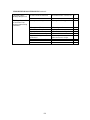
Ammonium-Nitrogen
Sensor Type...........Ion selective electrode
Range.....................0 to 200 mg/L-N
Accuracy................ +/- 10% of reading or 2 mg/L, whichever is greater
Resolution..............0.1 mg/L
Ammonia
Sensor Type...........Calculated from ammonium, pH, and temperature
Range.....................0 to 200 mg/L-N
Accuracy................ +/- 10% of reading or 2 mg/L, whichever is greater
Resolution..............0.1 mg/L
Turbidity
Sensor Type...........Optical, 90 degree scatter, mechanical cleaning
Range.....................0 to 1000 NTU
Accuracy................ +/- 5% of reading or 2 NTU, whichever is greater
Resolution..............0.1 NTU

1-6
1.4 HOW TO USE THIS MANUAL
The manual is organized to let you quickly understand and operate the 6000UPG system. However, it
cannot be stressed too strongly that informed and safe operation is more than just knowing which
buttons to push. An understanding of the principles of operation, calibration techniques, and
system setup is necessary to obtain accurate and meaningful results.
Sections 2 and 3 help you get started, providing initial setup information as well as calibration and
basic operating instructions. Sections 4 and 5 provide detailed information on the Sonde software
structure and YSI PC6000 software, respectively. PC6000 is PC-based software designed to help
the user to easily generate reports and plots from the data collected by the sonde. Sections 6-8
address principles of operation, sonde and sensor maintenance, and system troubleshooting.
Section 9 provides more detailed information on communications protocols. Section 10 provides
service and repair information. The appendices (A-H) provide information on safety, warranty,
accessories, options, storage recommendations, and more.
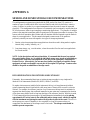
NOTE: Because of the many features, configurations and applications of this versatile product,
some sections of this manual may not apply to the specific system you have purchased.
The 6000
UPG can be purchased with or without internal battery power capability. Additionally, all
probes, cables and accessories can be ordered as options or ordered together as a system.
If you have any questions about this product or its application, please contact our customer service
department or authorized dealer for assistance. See Appendix C for contact information.

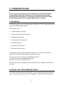
2-1
2. GETTING STARTED
This section is designed to quickly familiarize you with the hardware and software components of
the 6000
UPG sonde and its accessories. You will then proceed to sensor installations, cable
connections, software installation and finally basic communication with the 6000
UPG Sonde.
Diagrams, menu flow charts and basic written instructions will guide you through basic hardware
and software setup. For the first time user, we encourage the use a personal computer with PC6000
software during this initial setup procedure.
By the end of Section 2 you will have...
❏ Installed sensors in your sonde
❏ Installed PC6000 software in your PC
❏ Established communication between the sonde software and PC software
❏ Enabled appropriate sensors
❏ Assigned appropriate report parameters and units
Successful completion of the above list is essential for you to continue on to Section 3 which
focuses on performing calibrations and making measurements.
2.1 UNPACKING
Remove the instrument from the shipping container. Be careful not to discard any parts or supplies.
Check off all items on the packing list and inspect all assemblies and components for damage. If
any parts are damaged or missing, contact your representative immediately. If you do not know
from which dealer your 6000
UPG was purchased, refer to Appendix C for contact information.
NOTE: Reagents for the 6000
UPG are not packaged in the same carton as the instrument. These
materials must be ordered separately and will arrive in a separate package.
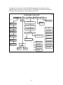
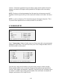
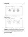
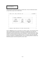
2.2 SYSTEM CONFIGURATION
There are a number of ways in which you may configure the 6000UPG Sonde with various
computers, terminals, and data collection devices. You should think about your particular
application needs and then make certain that you have all of the components you need to make
your system work. Below is a list of possible configurations that may be of interest to you. Each
is depicted in diagrammatic sketches on the next 3 pages.
❏ 6000
UPG Sonde to YSI 610 Display/Logger
❏ 6000
UPG Sonde to Portable Computer
❏ 6000
UPG Sonde to Data Collection Platform
❏ 6000
UPG Sonde to Lab Computer
❏ Upload Data from 6000
UPG Sonde to YSI 610-DM
❏ Upload Data Files from YSI 610 to Lab Computer

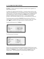
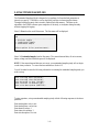
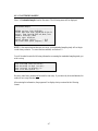
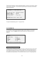
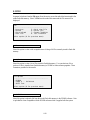
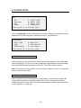
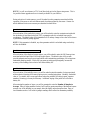
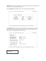
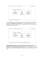
2-2
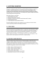
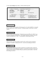
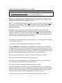
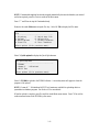
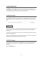
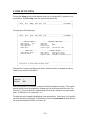
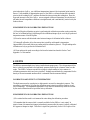
6000UPG Sonde to 610 Display/Logger
You will need...
❑ 6000UPG Sonde
❑ 610-D Display or
❑ 610-DM Display/Logger
❑ 6098 MS-8 Adapter for 610
YSI 610’s operate on rechargeable batteries.
Each 610 comes with a 110 VAC Wall Socket Charger Unit.
610-D or 610-DM
6098 MS-8 Adapter
6000UPG
610-D M
Environmental
Monitoring
Systems
YSI
Cable
MS-8
6000UPG Sonde
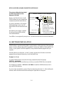
You will need...
❑ 6000UPG Sonde
❑ Computer with Com Port
❑ 6095B MS-8/DB-9 Adapter
6000UPG Sonde to Portable Computer
DB-9
MS-8
Adapter
6095B
Cable
6000UPG
6000UPG Sonde

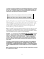
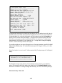
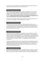
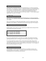
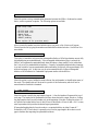
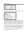
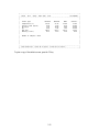
2-3
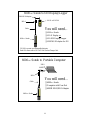
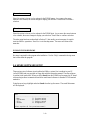
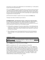
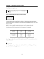
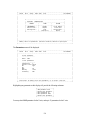
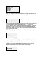
6000UPG Sonde to Data Collection Platform
You will need...
❑ 6000UPG Sonde
❑ 6096 Adapter with Leads
❑ Data Collection Platform
6096 MS-8 Adapter with Flying Leads
6000UPG
Cable
MS-8
6000UPG Sonde
DCP
6000UPG Sonde to Lab Computer
You will need...
❑ 6000UPG Sonde
❑ Computer with Com Port
❑ 6095B MS-8/DB-9 Adapter
❑ Power Supply *
❑ DB-9 to DB-25 Adapter may
be needed at Com Port
Cable
DB-9
Power Supply*
6037: 220 VAC
6038: 110 VAC
MS-8
Adapter
6095B
6000UPG
6000UPG Sonde
Not required if you use
sonde battery power.
*

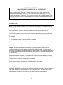
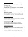
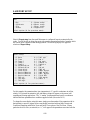
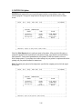
2-4
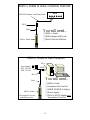
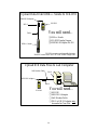
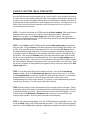
Upload Data from 6000UPG Sonde to 610-DM
YSI 610’s operate on rechargeable batteries.
Each 610 comes with a 110 VAC Wall Socket Charger Unit.
You will need...
❑ 6000UPG Sonde
❑ 610-DM Display/Logger
❑ 6098 MS-8 Adapter for 610
610-DM
6098 MS-8 Adapter
6000UPG
610-DM
Environmental
Monitoring
Systems
YSI
Cable
MS-8
6000UPG Sonde
Upload 610 Data Files to Lab Computer
You will need...
❑ 610-DM
❑ 6099 DB-9 Adapter
❑ Null Modem Cable
❑ DB-9 to DB-25 Adapter may
be needed at Com Port
610-DM
610-DM
Environmental
Monitoring
Systems
YSI
6099 DB-9 Adapter
Null Modem Cable
DB-9
DB-9

2-5
2.3 SONDE SETUP
In the following section, you will be provided with step-by-step instructions on how to get your
6000
UPG up and running. We recommend following the steps in the order listed. However,
depending on your sonde configuration and the optional sensors which you have purchased, some
of the steps may not apply to your setup. If so, simply skip to the next step in the protocol which is
relevant to your application.
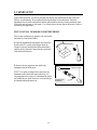
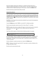
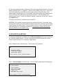
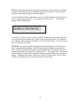
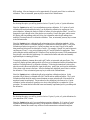
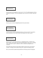
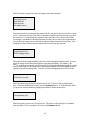
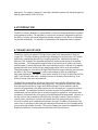
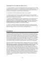
STEP 1. INSTALL YSI 6030 DO/COND/TEMP PROBE
Follow these instructions to prepare your new probe
and install it in the Model 6000
UPG.
1. Open the membrane kit and prepare the electrolyte.
Dissolve the KCl crystals in the dropper bottle by
filling it to the neck with distilled water and shaking
until the solid is dissolved. Insure that the crystals are
fully dissolved before use.
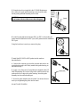
2. Remove the two protective caps and the dry
membrane from the 6030 probe.
NOTE: Your probe is shipped with a protective dry
membrane on the dissolved oxygen sensor tip. It is
very important not to scratch or contaminate the sensor
tip. Handle the new probe with care. Avoid touching or
accidentally hitting the sensor tip.
Protective Caps
Protective Dry
Membrane
Add distilled water

2-6
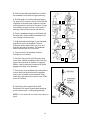
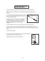
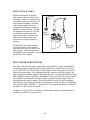
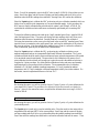
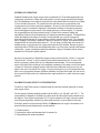
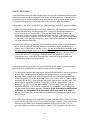
3. Follow the procedure described below to install a
new membrane on the dissolved oxygen sensor tip.
A. Hold the probe in a vertical position and apply a
few drops of KCl solution to the tip. The fluid should
completely fill the small moat around the electrodes
and form a meniscus on the tip of the sensor. Be sure
no air bubbles are stuck to the face of the sensor. If
necessary, shake off the electrolyte and start over.
B. Secure a membrane between your left thumb and
the probe body. Always handle the membrane with
care, touching it at the ends only.
C. With the thumb and forefinger of your right hand,
grasp the free end of the membrane. With one
continuous motion, gently stretch it up, over, and
down the other side of the sensor. The membrane
should conform to the face of the sensor.
D. Secure the end of the membrane under the
forefinger of your left hand.
E. Roll the O-ring over the end of the probe, being
careful not to touch the membrane surface with your
fingers. There should be no wrinkles or trapped air
bubbles. Small wrinkles may be removed by lightly
tugging on the edges of the membrane.
F. Trim off any excess membrane with a sharp knife or
scissors. Make sure the stainless steel temperature
sensor is not covered by excess membrane. Being
careful not to get water in the connector, rinse off the
excess KCl solution.
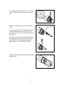
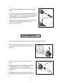
4. Using the hex driver supplied in the 6040
Maintenance Kit, remove the probe guard mounting
screws from the sonde. Set the probe guard aside.
NOTE: Do not remove the two allen screws above the
guard.
A
B
C
D
E F
Hex Driver
Probe Guard
Mounting
Screws
Probe
Guard

2-7
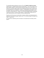
5. Locate the plug which seals the DO.C.T. port on the
sonde. Using the hex driver to assist you, remove the
plug.
6. Install the 6030 probe into the sonde as described
below.
A. Apply a very thin coat of O-ring lubricant (supplied
in the 6040 Maintenance Kit) to the O-ring on the
connector side of the probe. Insert the probe in the port
marked DO.C.T.
B. With the connectors aligned, screw down the probe
nut, making sure that the probe and sonde connectors
are fully meshed. Use the hex driver to assist you in
tightening the nut.
DO NOT OVER TIGHTEN.
7. Replace the probe guard and tighten the probe guard
mounting screws.
O-rin
g

2-8
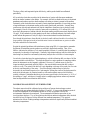
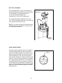
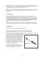
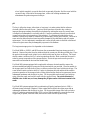
STEP 2. INSTALL OTHER PROBES
If you have purchased any optional YSI probes, follow instructions provided below for all items
other than the 6029 conductivity/temperature sensor which is installed in an identical fashion to the
6030. The 6031 pH, 6032 ORP, 6033 low ionic strength pH, 6084 nitrate, and 6083 ammonium
probes can be ordered as options and do not require factory installation (see Section 4.7 for
software setup). The 6026 turbidity probe is installed by the user according to its accompanying
instructions, but requires an additional PCB which must be factory installed. The depth sensors are
factory installed options.
Follow these instructions to prepare your new probe and install it in the 6000
UPG.
NOTE: Instructions for preparation of use, maintenance and storage are included with each
electrode.
1. Remove the storage bottle or hydrating cap and rinse the
glass portion of the electrode with distilled water.
2. Apply a very thin coat of O-ring lubricant (supplied in the
YSI 6040 Maintenance Kit) to the O-ring on the glass shaft of
the new electrode. Insert the electrode into the probe housing
and hand tighten.
DO NOT OVER TIGHTEN.
YSI 6031 pH Probe
YSI 6032 ORP Probe
YSI 6033 Low Ionic Strength pH Probe
Hydrating Cap
or Storage
l
Probe

2-9
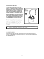
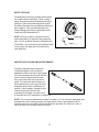
3. Using the hex driver (supplied in the YSI 6040 Maintenance
Kit), remove the probe guard mounting screws from the sonde.
Set the probe guard and mounting screws aside.
4. Locate the plug which seals the port ISE-1 or ISE-2 on the sonde. pH
probes must be installed in the ISE-1 port; ORP probes must be installed in
ISE-2 port.
Using the hex driver to assist you, remove the plug.
5. Install the 6031, 6032 or 6033 probes into the sonde as
described below.
A. Remove the connector cap from the electrode and check to be
certain the electrode is still firmly seated in the probe housing, as
described in Step 2.
B. Apply a very thin coat of O-ring lubricant (supplied in the YSI
6040 Maintenance Kit) to the O-ring on the connector side of the
probe and to the O-ring on the probe housing. Insert the probe
assembly into the selected sonde port.
C. Screw the probe assembly into the sonde. Use the hex driver to
assist you in tightening the probe into the sonde.
DO NOT OVER TIGHTEN.
CAUTION:
Do not remove the two allen screws above the guard.
Hex Driver
Guard
Do Not
Remove
These
Screws

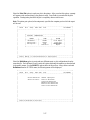
2-10
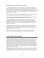
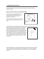
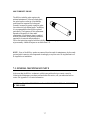
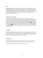
Follow these instructions to prepare your new probe and install it in the Model 6000UPG.
NOTE: Instructions for preparation of use, maintenance and storage are included with each
electrode.
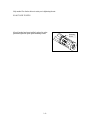
1. Note that the ammonium and nitrate probes consist of two
parts: A probe body and a membrane module which threads
into the end of the probe body.
2. Apply a very thin coat of O-ring lubricant (supplied in the
YSI 6040 Maintenance Kit) to the O-ring on membrane
module. Thread the membrane module into the end of the
probe body and tighten by hand until the units mesh
completely.
Do not over tighten and in no case ever use any tools such as pliers in this operation.
3.
Apply a very thin coat of O-ring lubricant (supplied in the YSI 6040 Maintenance Kit) to the
O-ring on the plastic shaft of the new electrode. Insert the electrode into the probe housing and hand
tighten.
DO NOT OVER TIGHTEN.
4.
Locate the plug which seals the port ISE-2 on the sonde. The ammonium
and nitrate sensors must be installed in this port.
Using the hex driver to assist you, remove the plug.
YSI 6083 Ammonium Probe
YSI 6032 Nitrate Probe
Probe
Page is loading ...
Page is loading ...
Page is loading ...
Page is loading ...
Page is loading ...
Page is loading ...
Page is loading ...
Page is loading ...
Page is loading ...
Page is loading ...
Page is loading ...
Page is loading ...
Page is loading ...
Page is loading ...
Page is loading ...
Page is loading ...
Page is loading ...
Page is loading ...
Page is loading ...
Page is loading ...
Page is loading ...
Page is loading ...
Page is loading ...
Page is loading ...
Page is loading ...
Page is loading ...
Page is loading ...
Page is loading ...
Page is loading ...
Page is loading ...
Page is loading ...
Page is loading ...
Page is loading ...
Page is loading ...
Page is loading ...
Page is loading ...
Page is loading ...
Page is loading ...
Page is loading ...
Page is loading ...
Page is loading ...
Page is loading ...
Page is loading ...
Page is loading ...
Page is loading ...
Page is loading ...
Page is loading ...
Page is loading ...
Page is loading ...
Page is loading ...
Page is loading ...
Page is loading ...
Page is loading ...
Page is loading ...
Page is loading ...
Page is loading ...
Page is loading ...
Page is loading ...
Page is loading ...
Page is loading ...
Page is loading ...
Page is loading ...
Page is loading ...
Page is loading ...
Page is loading ...
Page is loading ...
Page is loading ...
Page is loading ...
Page is loading ...
Page is loading ...
Page is loading ...
Page is loading ...
Page is loading ...
Page is loading ...
Page is loading ...
Page is loading ...
Page is loading ...
Page is loading ...
Page is loading ...
Page is loading ...
Page is loading ...
Page is loading ...
Page is loading ...
Page is loading ...
Page is loading ...
Page is loading ...
Page is loading ...
Page is loading ...
Page is loading ...
Page is loading ...
Page is loading ...
Page is loading ...
Page is loading ...
Page is loading ...
Page is loading ...
Page is loading ...
Page is loading ...
Page is loading ...
Page is loading ...
Page is loading ...
Page is loading ...
Page is loading ...
Page is loading ...
Page is loading ...
Page is loading ...
Page is loading ...
Page is loading ...
Page is loading ...
Page is loading ...
Page is loading ...
Page is loading ...
Page is loading ...
Page is loading ...
Page is loading ...
Page is loading ...
Page is loading ...
Page is loading ...
Page is loading ...
Page is loading ...
Page is loading ...
Page is loading ...
Page is loading ...
Page is loading ...
Page is loading ...
Page is loading ...
Page is loading ...
Page is loading ...
Page is loading ...
Page is loading ...
Page is loading ...
Page is loading ...
Page is loading ...
Page is loading ...
Page is loading ...
Page is loading ...
Page is loading ...
Page is loading ...
Page is loading ...
Page is loading ...
Page is loading ...
Page is loading ...
Page is loading ...
Page is loading ...
Page is loading ...
Page is loading ...
Page is loading ...
Page is loading ...
Page is loading ...
Page is loading ...
Page is loading ...
Page is loading ...
Page is loading ...
-
 1
1
-
 2
2
-
 3
3
-
 4
4
-
 5
5
-
 6
6
-
 7
7
-
 8
8
-
 9
9
-
 10
10
-
 11
11
-
 12
12
-
 13
13
-
 14
14
-
 15
15
-
 16
16
-
 17
17
-
 18
18
-
 19
19
-
 20
20
-
 21
21
-
 22
22
-
 23
23
-
 24
24
-
 25
25
-
 26
26
-
 27
27
-
 28
28
-
 29
29
-
 30
30
-
 31
31
-
 32
32
-
 33
33
-
 34
34
-
 35
35
-
 36
36
-
 37
37
-
 38
38
-
 39
39
-
 40
40
-
 41
41
-
 42
42
-
 43
43
-
 44
44
-
 45
45
-
 46
46
-
 47
47
-
 48
48
-
 49
49
-
 50
50
-
 51
51
-
 52
52
-
 53
53
-
 54
54
-
 55
55
-
 56
56
-
 57
57
-
 58
58
-
 59
59
-
 60
60
-
 61
61
-
 62
62
-
 63
63
-
 64
64
-
 65
65
-
 66
66
-
 67
67
-
 68
68
-
 69
69
-
 70
70
-
 71
71
-
 72
72
-
 73
73
-
 74
74
-
 75
75
-
 76
76
-
 77
77
-
 78
78
-
 79
79
-
 80
80
-
 81
81
-
 82
82
-
 83
83
-
 84
84
-
 85
85
-
 86
86
-
 87
87
-
 88
88
-
 89
89
-
 90
90
-
 91
91
-
 92
92
-
 93
93
-
 94
94
-
 95
95
-
 96
96
-
 97
97
-
 98
98
-
 99
99
-
 100
100
-
 101
101
-
 102
102
-
 103
103
-
 104
104
-
 105
105
-
 106
106
-
 107
107
-
 108
108
-
 109
109
-
 110
110
-
 111
111
-
 112
112
-
 113
113
-
 114
114
-
 115
115
-
 116
116
-
 117
117
-
 118
118
-
 119
119
-
 120
120
-
 121
121
-
 122
122
-
 123
123
-
 124
124
-
 125
125
-
 126
126
-
 127
127
-
 128
128
-
 129
129
-
 130
130
-
 131
131
-
 132
132
-
 133
133
-
 134
134
-
 135
135
-
 136
136
-
 137
137
-
 138
138
-
 139
139
-
 140
140
-
 141
141
-
 142
142
-
 143
143
-
 144
144
-
 145
145
-
 146
146
-
 147
147
-
 148
148
-
 149
149
-
 150
150
-
 151
151
-
 152
152
-
 153
153
-
 154
154
-
 155
155
-
 156
156
-
 157
157
-
 158
158
-
 159
159
-
 160
160
-
 161
161
-
 162
162
-
 163
163
-
 164
164
-
 165
165
-
 166
166
-
 167
167
-
 168
168
-
 169
169
-
 170
170
-
 171
171
-
 172
172


YSI 6000UPG Multiparameter Water Quality Monitor Owner's manual
- Category
- Measuring, testing & control
- Type
- Owner's manual
Ask a question and I''ll find the answer in the document
Finding information in a document is now easier with AI
Related papers
-
YSI PC6000 Software Owner's manual
-
-
-
-
-
-
-
YSI Pro1030 Quick start guide
-
-
YSI 51 Oxygen Meter Owner's manual
Other documents
-
Lovibond Single Method SD 70 - Conductivity User manual
-
 Hach SensION156 Quick Reference Instructions
-
 Hach Polymetron 9582sc User manual
-
 SCHONSTEDT 910 Sonde Owner's manual
-
Hanna Instruments HI98199 Owner's manual
-
Hach sensION+ pH1 User manual
-
 Bante Instruments series Portable pH/ORP/Ion/Conductivity/DO Meter Owner's manual
-
 Hach ORBISPHERE 410 Quick Operator's Manual
-
 Hach sensION MM340 User manual
-
 palintest SA1100 User manual


