Invacare Titanium Heavy Duty Owner's Operator And Maintenance Manual
- Category
- Cable clamps
- Type
- Owner's Operator And Maintenance Manual

Owner’s Operator and Maintenance Manual
DEALER: This manual MUST be given to
the user of the wheelchair.
USER:
BEFORE using this wheelchair, read
this manual and save for future reference.
For more information regarding
Invacare products, parts, and services,
please visit www.invacare.com
Everyday and Sport Series
Wheelchairs
Top End Everyday Series
Terminator™ Titanium and Titanium Heavy Duty
Terminator™ Everyday and Everyday Heavy Duty
Top End Sports Series
Terminator™ BB
X-Terminator™ BB
Paul Schulte Signature BB
X-Terminator™ Titanium
X-Terminator™ QR
Transformer™ All Sport
T-5 Tennis Elite
®

Everyday and Sport Series Wheelchairs 2 Part No 1122172
WARNING
DO NOT OPERATE THIS EQUIPMENT WITHOUT FIRST READING
AND UNDERSTANDING THIS MANUAL. IF YOU ARE UNABLE TO
UNDERSTAND THE WARNINGS, CAUTIONS AND
INSTRUCTIONS, CONTACT YOUR INVACARE DEALER OR
INVACARE CUSTOMER SUPPORT BEFORE ATTEMPTING TO USE
THIS EQUIPMENT - OTHERWISE INJURY AND/OR EQUIPMENT
DAMAGE MAY OCCUR.
NOTE:Updatedversionsofthismanualareavailableonwww.invacare.com.

TABLE OF CONTENTS
Part No 1122172 3 Everyday and Sport Series Wheelchairs
TABLE OF CONTENTS
SPECIAL NOTES ................................................................................ 6
TYPICAL PRODUCT PARAMETERS .................................................... 8
Tyre Pressure Conversion .....................................................................................................................14
SECTION 1—GENERAL GUIDELINES ................................................. 15
Stability Warning.......................................................................................................................................15
Operating Information.............................................................................................................................15
Tyre Pressure and Information .............................................................................................................17
Weight Training ........................................................................................................................................17
Weight Limitation.....................................................................................................................................17
SECTION 2—SAFE HANDLING ......................................................... 18
Stability and Balance.................................................................................................................................18
Coping with Everyday Obstacles......................................................................................................19
A Note to Wheelchair Assistants....................................................................................................19
Percentage of Weight Distribution ......................................................................................................19
Reaching, Leaning and Bending - Forward......................................................................................20
Reaching, Leaning - Backwards .........................................................................................................20
Tipping.........................................................................................................................................................21
Tipping - Curbs .........................................................................................................................................21
Stairways.....................................................................................................................................................22
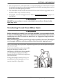
Transferring To and From Other Seats ..............................................................................................23
SECTION 3—SAFETY INSPECTION ................................................... 24
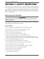
Safety Inspection Checklist.....................................................................................................................24
Inspect Initially ......................................................................................................................................24
Inspect/Adjust Weekly........................................................................................................................25
Inspect/Adjust Monthly.......................................................................................................................25
Inspect/Adjust Periodically.................................................................................................................26
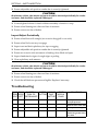
Troubleshooting........................................................................................................................................26
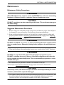
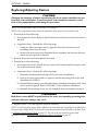
Maintenance...............................................................................................................................................27
Maintenance Safety Precautions .......................................................................................................27
Suggested Maintenance Procedures ................................................................................................27
SECTION 4—BACK ......................................................................... 29
Unfolding/Folding the Back.....................................................................................................................29
Back Angle Adjustment..........................................................................................................
.................29
Removing/Installing Foldover Back Upholstery .................................................................................31
Removing Foldover Back Upholstery..............................................................................................31
Installing Foldover Back Upholstery ................................................................................................31

TABLE OF CONTENTS
Everyday and Sport Series Wheelchairs 4 Part No 1122172
TABLE OF CONTENTS
Adjustable Tension Back Upholstery...................................................................................................32
The Adjustable Tension Straps.........................................................................................................32
The Back Upholstery Cover..............................................................................................................32
Replacing Adjustable Tension Back Upholstery............................................................................32
Back Height Adjustment (Adjustable Backs Only)............................................................................33
SECTION 5—WHEELS ....................................................................... 35
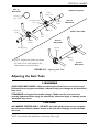
Removing/Installing Rear Wheels .........................................................................................................35
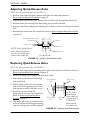
Adjusting Quick-Release Axles..............................................................................................................36
Replacing Quad-Release Axles ..............................................................................................................36
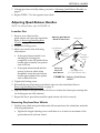
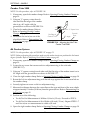
Adjusting Quad-Release Handles..........................................................................................................37
In and/or Out........................................................................................................................................37
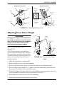
Removing Play from Rear Wheels ...................................................................................................37
Handrim Replacement.............................................................................................................................38
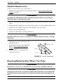
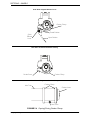
Repairing/Replacing Rear Wheel, Tyre/Tube.....................................................................................38
Opening/Closing Camber Clamps ........................................................................................................39
Adjusting Rear Wheel Camber .............................................................................................................41
Camber Tube 2000..............................................................................................................................41
A4 Camber System..............................................................................................................................41
Determining Toe In/Toe Out................................................................................................................42
Adjusting Toe In/Toe Out......................................................................................................................43
Camber Tube 2000..............................................................................................................................43
A4 Camber System..............................................................................................................................44
Course Adjustment .......................................................................................................................44
Fine Adjustment .............................................................................................................................45
Adjusting Wheelbase Length (Adjusting Center of Gravity)..........................................................46
Adjusting Wheelbase Width..................................................................................................................48
Camber Tube 2000..............................................................................................................................48
A4 Camber System..............................................................................................................................48
Replacing Axle Tube ................................................................................................................................49
Adjusting the Axle Tube .........................................................................................................................51
Camber Tube 2000..............................................................................................................................52
A4 Camber System..............................................................................................................................52
Replacing/Adjusting Castors...................................................................................................................54
Adjusting Front Castor Height..............................................................................................................55
Wheel Lock Adjustment/Replacement................................................................................................56
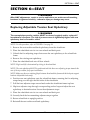
SECTION 6—SEAT ........................................................................... 57
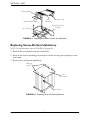
Replacing Adjustable Tension Seat Upholstery .................................................................................57
Replacing Screw-On Seat Upholstery..................................................................................................58

TABLE OF CONTENTS
Part No 1122172 5 Everyday and Sport Series Wheelchairs
TABLE OF CONTENTS
Adjusting Transformer Seat Height......................................................................................................59
Adjusting Front Seat Height ..............................................................................................................59
Adjusting Rear Seat Height................................................................................................................59
SECTION 7—FOOTREST/ANTI-TIPPER .............................................. 61
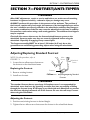
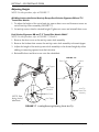
Adjusting/Replacing Standard Footrest................................................................................................61
Replacing the Footrest........................................................................................................................61
Adjusting the Footrest........................................................................................................................61
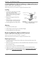
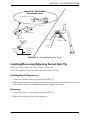
Installing/Adjusting Optional Clamp on Raised Footrest ................................................................62
Installing..................................................................................................................................................62
Adjusting ................................................................................................................................................62
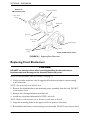
Replacing/Adjusting Optional A4 Footrest.........................................................................................62
Replacing the Footrest........................................................................................................................62
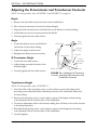
Adjusting Footplate Angle..................................................................................................................63
Adjusting Footplate Depth.................................................................................................................63
Installing the X-Terminator Footrest...................................................................................................63
Adjusting the X-terminator and Transformer Footrests................................................................64
Depth......................................................................................................................................................64
Angle .......................................................................................................................................................64
X-Terminator Height..........................................................................................................................64
Transformer Height.............................................................................................................................64
Adjusting/Replacing Anti-Tipper ...........................................................................................................65
Adjusting Anti-tipper...........................................................................................................................66
Replacing Anti-tipper...........................................................................................................................66
Installing/Removing/Adjusting Swivel Anti-Tip...................................................................................67
Installing/Depth Adjustment..............................................................................................................67
Removing ...............................................................................................................................................67
Adjusting Height...................................................................................................................................68
All Wheelchairs with Swivel Anti-tip Except
Paul Schulte Signature BB and T-5 Tennis Elite Models ........................................................68
Paul Schulte Signature BB and T-5 Tennis Elite Models ONLY ..........................................68
SECTION 8—SUSPENSION ............................................................... 69
Elastomers and Suspension ....................................................................................................................69
Replacing Rear Elastomers ......................................................................................................
...............69
Replacing Front Elastomers....................................................................................................................70
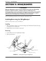
SECTION 9—WING/BUMPER ............................................................ 72
Installing/Removing the Wing/Bumper ................................................................................................72
Installing..................................................................................................................................................72
Removing ...............................................................................................................................................72
NOTES ........................................................................................... 73
LIMITED WARRANTY ..................................................................... 75

SPECIAL NOTES
Everyday and Sport Series Wheelchairs 6 Part No 1122172
SPECIAL NOTES
Signalwordsareusedinthismanualandapplytohazardsorunsafepracticeswhich
couldresultinpersonalinjuryorpropertydamage.Refertothetablebelowfor
definitionsofthesignalwords.
WARNING/CAUTIONnoticesasusedinthismanualapplytohazardsorunsafe
practiceswhichcouldresultinpersonalinjuryorpropertydamage.
NOTICE
THE INFORMATION CONTAINED IN THIS DOCUMENT IS SUBJECT TO
CHANGE WITHOUT NOTICE.
Serial number information is located under the seat of the chair.
As a manufacturer of wheelchairs, Invacare endeavors to supply a wide variety of
wheelchairs to meet many needs of the end user. However, final selection of the
type of wheelchair to be used by an individual rests solely with the user and his/her
healthcare professional capable of making such a selection.
Some countries require product returned for service be cleaned and sanitized.
Please consult your dealer prior to returning product.
WHEELCHAIR TIE-DOWN RESTRAINTS AND SEAT POSITIONING STRAPS
Invacare recommends that wheelchair users NOT be transported in vehicles of any
kind while in wheelchairs. As of this date, the Department of Transportation has not
approved any tie-down systems for transportation of a user while in a wheelchair, in
a moving vehicle of any type.
It is Invacare’s position that users of wheelchairs should be transferred into
appropriate seating in vehicles for transportation and use be made of the restraints
made available by the auto industry. Invacare cannot and does not recommend any
wheelchair transportation systems.
AS REGARDS RESTRAINTS - SEAT POSITIONING STRAPS - IT IS THE OBLIGA-
TION OF THE DEALER, THERAPISTS AND OTHER HEALTHCARE PROFES-
SIONALS TO DETERMINE IF A SEATING POSITIONING STRAP IS REQUIRED
TO ENSURE THE SAFE OPERATION OF THIS EQUIPMENT BY THE USER.
SERIOUS INJURY CAN OCCUR IN THE EVENT OF A FALL FROM A WHEEL-
CHAIR.
SIGNAL WORD MEANING
WARNING
Warning indicates a potentially hazardous situation which, if not avoided,
could result in death or serious injury.
CAUTION
Caution indicates a potentially hazardous situation which, if not avoided,
may result in property damage.

SPECIAL NOTES
Part No 1122172 7 Everyday and Sport Series Wheelchairs
WARNING
The seat positioning strap is a positioning belt only. It is not designed for use as a
safety device withstanding high stress loads such as auto or aircraft safety belts. If
signs of wear appear, belt MUST be replaced immediately.
ACCESSORIES WARNING
Invacare products are specifically designed and manufactured for use in conjunction
with Invacare accessories. Accessories designed by other manufacturers have not
been tested by Invacare and are not recommended for use with Invacare products.
Because TOP END wheelchairs are made to the specifications of the original own-
ers it is unlikely that refurbished product would be suitable to other user’s needs.

TYPICAL PRODUCT PARAMETERS
Everyday and Sport Series Wheelchairs 8 Part No 1122172
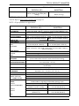
TYPICAL PRODUCT PARAMETERS
NOTE:Allspecificationsareapproximate.
TERMINATOR
EVERYDAY (ED) BASKETBALL
FRAME: Rigid - 4130 Chrome-moly
SEAT WIDTH: 12-20 inches (30.48 - 50.8 cm) - Outside to Outside of SEAT FRAME in 1-inch
(2.54 cm) increments
SEAT DEPTH: 14 to 17 (35.56 - 43.18 cm) inches
SEAT-TO-FLOOR: Front - 17 to 21-inch (43.18 - 53.34 cm),
Rear -14 to 21-inch (35.56 - 53.34 cm)
Front - 17 to 21-inch (43.18 - 53.34 cm),
Rear -13 to 21-inch (33.02 - 53.34 cm)
BACK STYLE: Fixed (Standard), Fold Down
BACK HEIGHT
8 -16 inches (20.32 - 40.64 cm) 8 - 14 inches (20.32 - 35.56)FIXED:
ADJUSTABLE: 8 to 11, 10 to 14, 12 to 16, 14 to 18 and 16 to 20 inches in 1-inch increments
(20.32 - 27.94, 25.4 - 35.56, 30.48 - 40.64, 35.56 - 45.72, and 40.64 - 50.8 cm in
2.54 cm increments)
BACK ANGLE
FOLDING: 90° straight, 4° backward, 4° forward or 8° forward
FIXED: 0°, 3°, 6° or 9°
REAR-FRONT CASTOR
DISTANCE:
17 to 21 Inches (43.18 - 53.34 cm) (From outside of back of frame to center of front
castor housing)
FRONT CASTOR TO
FOOTPLATE DISTANCE: 3 - 5 inches (7.62 - 12.7 cm)
FOOT WIDTH: 9 - 12 inches (22.86 - 30.48 cm) (Average is 10 inches (25.4 cm) between front of
footrest bars)
FOOTREST: Tubular: 4-inch (10.16 cm) Height Adjustable (Standard)
SIDE-WHEEL CLEARANCE:
Adjustable 1/2 to 1-1/2 inches (1.27 - 3.81 cm)
REAR AXLE: Adjustable Axle Position, Quick (Standard) or Quad-Release
REAR WHEEL CAMBER
CAMBER TUBE 2000: 0°, 3°, 6°, 9°, 12°, 15°, 18°, 20°
A4™CAMBER SYSTEM: 0°, 3°, 6°, 9°, 12° Optional
REAR WHEELS AND
TYRES*
Double walled rim high flange hub (Standard), Spinergy® Spox
22-INCH: 22x1-3/8-inch (55.88x3.5 cm) (Standard) N/A
24-INCH (STANDARD): Primo 25-540 (Standard), 24x1-3/8-inch
(60.69x3.5 cm), KIK® , Knobby Primo 25-540 (Standard)
25-INCH: Primo 25-559 (Standard), KIK, Knobby Primo 25-559 (Standard)
26-INCH: Primo 25-590 (Standard), 26x1-3/8-inch
(60.96x3.5 cm) Primo 25-590 (Standard)
700C: Special Turbo (Standard)
HANDRIMS: Aluminum Welded Tab (Standard) Plastic
Coated, Natural Fit®, Titanium
Aluminum Welded Tab (Standard),
Titanium
WHEEL LOCKS: High Mount, Low Mount (Standard) N/A
FRONT FORKS: Non-Suspension (Standard), Suspension Non-Suspension
CASTOR SIZE: 3, 4, 5 and 6-inch
(7.62, 10.16, 12.7 and 15.24 cm) 3-inch (7.62 cm) Solid
BACK UPHOLSTERY: U240 Black - Adjustable Tension
WEIGHT: 20 lbs (9.07 kg)
SHIPPING WEIGHT: 30 lbs (13.6 kg)

TYPICAL PRODUCT PARAMETERS
Part No 1122172 9 Everyday and Sport Series Wheelchairs
NOTE:15x15‐inchseat,rearwheelsandminimaloptionsareincludedintheweight.
*NOTE:RefertoTyrePressureConversiononpage 14.
NOTE:Allspecificationsareapproximate.
WEIGHT LIMITATION: 250 lbs (113.4 kg)
350 lbs (158.76 kg) with Heavy Duty
Package 250 lbs (113.4 kg)
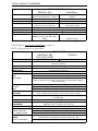
TERMINATOR TITANIUM
EVERYDAY (ED) BASKETBALL
FRAME: Rigid - 4130 Chrome-moly
SEAT WIDTH: 12-20 inches (30.48 - 50.8 cm) - Outside to Outside of SEAT FRAME in 1-inch
(2.54 cm) increments
SEAT DEPTH: 14 to 18 (35.56 - 45.72 cm) inches
SEAT-TO-FLOOR: Front - 17 to 21-inch (43.18 - 53.34 cm),
Rear -14 to 21-inch (35.56 - 53.34 cm)
Front - 17 to 21-inch (43.18 - 53.34 cm),
Rear -13 to 21-inch (33.02 - 53.34 cm)
BACK STYLE: Fixed (Standard), Fold Down
BACK HEIGHT
8 -16 inches (20.32 - 40.64 cm) 8 - 14 inches (20.32 - 35.56 cm)FIXED:
ADJUSTABLE: 8 to 11, 10 to 14, 12 to 16, 14 to 18 and 16 to 20 inches in 1-inch increments.
(20.32 - 27.94, 25.4 - 35.56, 30.48 - 40.64, 35.56 - 45.72, and 40.64 - 50.8 cm in
2.54 cm increments)
BACK ANGLE
FOLDING: 90° straight, 4° backward, 4° forward or 8° forward
FIXED: 0°, 3°, 6° or 9°
REAR-FRONT CASTOR
DISTANCE:
17 to 2 inches (43.18 - 53.34 cm)
(From outside of back of frame to center of front castor housing)
FRONT CASTOR TO
FOOTPLATE DISTANCE: 3 to 5 inches (7.62 - 12.7 cm)
FOOT WIDTH: 9 to 12 inches (22.86 - 30.48 cm) (Average is 10-inches (25.4 cm) between front of
footrest bars)
FOOTREST: Tubular: 4-inch (10.16 cm) Height Adjustable (Standard)
SIDE - WHEEL
CLEARANCE: Adjustable 1/2 to 1-1/2-inches (1.27 - 3.81 cm)
REAR AXLE: Adjustable Axle Position, Quick (Standard) or Quad-Release
REAR WHEEL CAMBER
CAMBER TUBE 2000: 0°, 3°, 6°, 9°, 12°, 15°, 18°, 20°
A4™CAMBER SYSTEM: 0°, 3°, 6°, 9°, 12°
REAR WHEELS AND
TYRES*: Double walled rim high flange hub (Standard), Spinergy® Spox
22-INCH: 22x1-3/8-inch (55.88x3.5 cm) (Standard) N/A
24-INCH (STANDARD): Primo 25-540 (Standard), 24x1-3/8-inch
(60.69x3.5 cm), KIK®, Knobby Primo 25-540 (Standard)
25-INCH: Primo 25-559 (Standard), KIK, Knobby Primo 25-559 (Standard)
26-INCH: Primo 25-590 (Standard), 26x1-3/8-inch
(60.69x3.5 cm) Primo 25-590 (Standard)
700C: Special Turbo (Standard)
TERMINATOR
EVERYDAY (ED) BASKETBALL

TYPICAL PRODUCT PARAMETERS
Everyday and Sport Series Wheelchairs 10 Part No 1122172
NOTE:15x15‐inchseat,rearwheelsandminimaloptionsareincludedintheweight.
*NOTE:RefertoTyrePressureConversion
onpage 14.
NOTE:Allspecificationsareapproximate.
HANDRIMS: Aluminum Welded Tab (Standard)
Plastic Coated, Natural Fit®, Titanium
Aluminum Welded Tab (Standard),
Titanium
WHEEL LOCKS: High Mount, Low Mount (Standard) N/A
FRONT FORKS: Non-Suspension (Standard), Suspension Non-Suspension
CASTOR SIZE: 3, 4, 5 and 6-inch
(7.62, 10.16, 12.7 and 15.24 cm) 3-inch (7.62 cm) Solid
BACK UPHOLSTERY: U240 Black - Adjustable Tension
WEIGHT: 17 lbs (7.71 kg)
SHIPPING WEIGHT: 30 lbs (13.6 kg)
WEIGHT LIMITATION: 250 lbs (113.4 kg)
400 lbs (181.44 kg) with Heavy Duty
Package 250 lbs (113.4 kg)
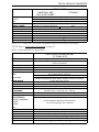
X-TERMINATOR
BASKETBALL (BB)
AND QUAD RUGBY
TITANIUM
FRAME: Rigid - 4130 Chrome-moly Rigid - 3-2.5 Titanium
SEAT WIDTH: 12-20 inches (30.48 - 50.8 cm) - Outside to Outside of SEAT FRAME in 1-inch
(2.54 cm) increments
SEAT DEPTH: 14 to 17 (35.56 - 43.18 cm) inches
SEAT-TO-FLOOR: Front - 17 to 21-inch (43.18 - 53.34 cm), Rear -13 to 21-inch (33.02 - 53.34 cm)
BACK STYLE: Fixed (Standard), Fold Down
BACK HEIGHT
FIXED: 8 to 14 inches (35.56 - 45.72 cm)
ADJUSTABLE: 8 to 11, 10 to 14, 12 to 16, 14 to 18 and 16 to 20 inches in 1-inch increments.
(20.32 - 27.94, 25.4 - 35.56, 30.48 - 40.64, 35.56 - 45.72, and 40.64 - 50.8 cm in
2.54 cm increments)
BACK ANGLE
FOLDING: 90° straight, 4° backward, 4° forward or 8° forward
FIXED: 0°, 3°, 6° or 9°
REAR-FRONT CASTOR
DISTANCE:
22, 24, and 26 inches (55.88, 60.96, 66.04)
(From outside of back of frame to center of front castor housing)
FOOT WIDTH: 9 to 12-inches (22.86 - 30.48 cm) (Average is 10-inches (25.4 cm) between front of
footrest bars)
FOOTREST: Tubular: 4-inch (10.16 cm) Height Adjustable (Standard)
SIDE - WHEEL
CLEARANCE: Adjustable 1/2 to 1-1/2 inches (1.27 - 3.81 cm)
REAR AXLE: Adjustable Axle Position, Quick (Standard) or Quad-Release
REAR WHEEL CAMBER
CAMBER TUBE 2000: 0°, 3°, 6°, 9°, 12°, 15°, 18°, 20°
A4™CAMBER SYSTEM: N/A
REAR WHEELS AND
TYRES*: Double walled rim high flange hub (Standard), Spinergy® Spox
24-INCH (STANDARD): Primo 25-540
TERMINATOR TITANIUM
EVERYDAY (ED) BASKETBALL

TYPICAL PRODUCT PARAMETERS
Part No 1122172 11 Everyday and Sport Series Wheelchairs
NOTE:15x15‐inchseat,rearwheelsandminimaloptionsareincludedintheweight.
*NOTE:RefertoTyrePressureConversiononpage 14.
NOTE:Allspecificationsareapproximate.
25-INCH: Primo 25-559 (Standard)
26-INCH: Primo 25-590 (Standard)
700C: Special Turbo (Standard)
HANDRIMS: Aluminum Welded Tab, Titanium
WHEEL LOCKS: High Mount, Low Mount (Standard) N/A
FRONT FORKS: Non-Suspension
CASTOR SIZE: 3-inch (7.62 cm) Solid
BACK UPHOLSTERY: U240 Black - Adjustable Tension
WEIGHT: 23 lbs (10.44 kg)
SHIPPING WEIGHT: 30 lbs (13.6 kg)
WEIGHT LIMITATION: 250 lbs (113.4 kg)
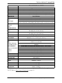
PAUL SCHULTE SIGNATURE BB/
T-5 TENNIS ELITE
FRAME: Rigid - 6061T6 Aluminum or 3-2.5 Titanium
SEAT WIDTH: 12-19 inches (30.48 - 48.26 cm) - Outside to Outside of SEAT FRAME in 1-inch
(2.53 cm) increments
SEAT DEPTH: 14 to 18-inches (35.56 - 45.72 cm)
SEAT-TO-FLOOR: Front - 17 to 21-inch (43.18 - 53.34 cm), Rear -13 to 21-inch (33.02 - 53.34 cm)
BACK STYLE: Fixed
BACK HEIGHT
FIXED: 8 to 14 inches (35.56 - 45.72 cm)
ADJUSTABLE: 11 to 14, 14 to 18, 16 to 20 inches in 1-inch increments.
(27.94 to 35.56, 35.56 to 45.72, 40.64 to 50.8 cm in 2.54 cm increments)
BACK ANGLE: Fixed 0° (Set at 90° to floor)
WHEELBASE: 16, 17, 18, or 19 inches (40.64, 43.18, 45.72, or 48.26 cm)
FOOTREST: Tubular: 4-inch (10.16 cm) Height Adjustment
SIDE - WHEEL
CLEARANCE: Adjustable 1/2 to 1-1/2 inches (1.27 - 3.81 cm)
REAR AXLE: Fixed Axle Position, Quick Release (Standard)
REAR WHEEL CAMBER: Fixed: 12°, 15°, 18° or 20°
REAR WHEELS*:
Double Walled Rim High Flange Hub (Standard),
Cross Spoke, Spinergy® Spox (Optional)
24-INCH (STANDARD):
25-INCH:
26-INCH:
700C:
HANDRIMS: Aluminum Welded Tab (Standard), Titanium (Optional)
WHEEL LOCKS: N/A
FRONT FORKS: Fits 3-inch (7.62 cm) Wheel Non-Suspension (Standard)
CASTOR SIZE: 3-inch (7.62 cm) Solid (Standard), Lighted (Optional)
BACK UPHOLSTERY: U240 Black - Adjustable Tension
WEIGHT: 22 lbs (9.98 kg) (Aluminium), 20 lbs (9.07 kg) (Titanium)
X-TERMINATOR
BASKETBALL (BB)
AND QUAD RUGBY
TITANIUM

TYPICAL PRODUCT PARAMETERS
Everyday and Sport Series Wheelchairs 12 Part No 1122172
NOTE:15x15‐inchseat,rearwheelsandminimaloptionsareincludedintheweight.
*NOTE:RefertoTyrePressureConversiononpage 14.
NOTE:Allspecificationsareapproximate.
SHIPPING WEIGHT: 30 lbs (13.6 kg)
WEIGHT LIMITATION: 250 lbs (113.4 kg)
PAUL SCHULTE SIGNATURE BB/
T-5 TENNIS ELITE

TYPICAL PRODUCT PARAMETERS
Part No 1122172 13 Everyday and Sport Series Wheelchairs
NOTE:15x15‐inchseat,rearwheelsandminimaloptionsareincludedintheweight.
*NOTE:RefertoTyrePressureConversiononpage 14.
TRANSFORMER ALL-SPORT
FRAME: Rigid - 606IT6 Aluminium
SEAT WIDTH: 12-20 inches (30.48 - 50.8 cm) - Outside to Outside of SEAT FRAME in 1-inch increments
SEAT DEPTH: 12 to 20-inches (30.48 - 50.8 cm)
SEAT-TO-FLOOR:
TALL FRAME: Front - 18 to 21-inch (45.72 - 53.34 cm), Rear -15 to 21-inch (38.1 - 53.34 cm)
SHORT FRAME Front - 16 to 18-inch (40.64 - 45.72 cm), Rear -15 to 18-inch (38.1 - 45.72 cm)
BACK STYLE: Fixed, Fold Down
BACK HEIGHT:
FIXED: 8 to 14 inches (20.32 - 45.72 cm)
ADJUSTABLE: 8 to 11, 10 to 14, 12 to 16 and 14 to 18 in 1-inch increments.
(20.32 to 27.94, 25.4 to 35.56, 30.48 to 40.6, 35.56 to 45.72 cm in 2.54 cm increments)
BACK ANGLE: Fixed 0° (Set at 90° to floor)
FOLDING: Adjustable in 5° increments
FIXED: Set at 90° to floor
FRAME LENGTH:
FRAME W/FOLDING
BACK: Seat depth plus 10 inches (25.4 cm)
FRAME W/FIXED
BACK: Seat depth plus 8 inches (20.32 cm)
FOOTREST: Recessed: 4-inch (10.16 cm) Height/Angle Adjustable, Solid Platform (Standard)
SIDE - WHEEL
CLEARANCE: Adjustable 1/2 to 1-1/2 inches (1.27 - 3.81 cm)
REAR AXLE: Adjustable Axle Position, Quick-Release
REAR WHEEL CAM-
BER: Fixed: 12°, 15°, 18° or 20°
CAMBER TUBE 2000: 0°, 3°, 6°, 12°, 15°, 18°, 20°
A4 CAMBER SYSTEM: Optional
REAR WHEELS*: Double walled rim high flange hub (standard), Spinergy® Spox (optional)
24-INCH (STANDARD): Primo 25-540, Continental (Optional)
25-INCH: Primo 25-559 (Standard)
26-INCH: Primo 25-590 (Standard)
700C: Special Turbo (Standard)
HANDRIMS: Aluminum Welded Tab (Standard)
WHEEL LOCKS: N/A
FRONT FORKS: Non-Suspension (Standard)
CASTOR SIZE: 3-inch (7.62 cm)
BACK UPHOL-
STERY: U240 Black - Foldover
WEIGHT: 20 lbs. (9.07 kg)
SHIPPING WEIGHT: 30 lbs. (13.6 kg)
WEIGHT
LIMITATION: 250 lbs. (133.40 kg)

TYPICAL PRODUCT PARAMETERS
Everyday and Sport Series Wheelchairs 14 Part No 1122172
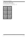
Tyre Pressure Conversion
NOTE:PSIratingisprintedonthesideofthetyre.
NOTE:Conversionformula:1psi=6.895kPa(appox.7kPa).
PSI KILOPASCALS
50 345
55 379
60 414
65 448
70 483
75 517
80 552
85 586
90 621
95 655
100 690
105 724
110 758
115 793
120 827

SECTION 1—GENERAL GUIDELINES
Part No 1122172 15 Everyday and Sport Series Wheelchairs
SECTION 1—GENERAL GUIDELINES
WARNING
SECTION 1 - GENERAL GUIDELINES contains important information for the safe
operation and use of this product. DO NOT use this product or any available
optional equipment without first completely reading and understanding these
instructions and any additional instructional material such as Owner’s Manuals,
Service Manuals or Instruction Sheets supplied with this product or optional
equipment. If you are unable to understand the Warnings, Cautions or Instructions,
contact a healthcare professional, dealer or technical personnel before attempting
to use this equipment - otherwise, injury or damage may occur.
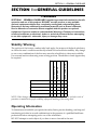
Stability Warning
Thepositionofthefootrest,cambertube,backangle,thetautnessofthebackupholstery
aswellastheuserʹsconditionaredirectlyrelatedtothewheelchairsstability.Anychange
tooneoranycombinationofthefivemaycausethewheelchairtodecreaseinstability.
Useextremecautionwhenusinganewseatingposition.Theadditionofanti‐tippersmay
berequired.
NOTE:Whenchangestothelefthandcolumnoccur,followacrossthechartandrefertothe
✓
proceduretomaintaintheproperstability,safetyandhandling of theracingchair.
Operating Information
Todetermineandestablishyourparticularsafetylimits,practicebending,reachingand
transferringactivitiesinseveralcombinationsinthepresenceofaqualifiedhealthcare
professionalbeforeattemptingactiveuseofthewheelchair.
DONOTattempttoreachobjectsifyouhavetomoveforwardintheseat.
FOOTREST POSITION
CAMBER TUBE
BACK ANGLE
BACK UPHOLSTERY
USER CONDITION
FOOTREST POSITION ●
✓✓
CAMBER TUBE ●
✓✓
BACK ANGLE
✓
●
✓✓
BACK UPHOLSTERY
✓
●
✓
USER CONDITION
✓✓✓✓
●

SECTION 1—GENERAL GUIDELINES
Everyday and Sport Series Wheelchairs 16 Part No 1122172
DONOTattempttoreachobjectsifyouhavetopickthemupfromthefloorbyreaching
downbetweenyourknees.
DONOTleanoverthetopofthebackupholsterytoreachobjectsfrombehindasthismay
causethewheelchairtotipover.
DONOTshiftyourweightorsittingpositiontowardthedirectionyouarereachingasthe
wheelchairmaytipover.
DONOTtipthewheelchairwithoutassistance.
DONOTuseanescalatortomoveawheelchairbetweenfloors.Seriousbodilyinjurymay
occur.Beforeattemptingtotransferinoroutofthewheelchair,everyprecautionshould
betakentoreducethegapdistance.Turnbothcastorsparalleltotheobjectyouare
transferringonto.Alsobecertainthewheellocksareengagedtopreventthewheelsfrom
moving.
DONOToperateonroads,streetsorhighways.
DONOTclimb,goupordownrampsortraverseslopesgreaterthan9°.
DONOTattempttomoveupordownaninclinewithawater,iceoroilfilm.
DONOTattempttorideovercurbsorobstacles.Doingsomaycauseyourwheelchairto
turnoverandcausebodilyharmordamagetothewheelchair.
Invacareproductsarespecificallydesignedandmanufacturedforuseinconjunctionwith
Invacareaccessories.Accessoriesdesignedbyothermanufacturershavenotbeentested
byInvacareandarenotrecommendedforusewithInvacareproducts.
BecauseTOPENDwheelchairsaremadetothespecificationsoftheoriginalownersitis
unlikelythatrefurbishedproductwouldbesuitabletootheruser’sneeds.
DONOTattempttoliftthewheelchairbyanyremovable(detachable)parts.Liftingby
meansofanyremovable(detachable)partsofawheelchairmayresultininjurytotheuser
ordamagetothewheelchair.
DONOTstandontheframeofthewheelchair.
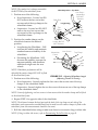
Checkallallenscrewsthatsecure
thefootrest/raisedfootrestsystemtothechairframe
beforeusingthewheelchair,especiallyifengaginginanycontactsport.
Anti‐tippersMUSTBEattachedatalltimes.Inasmuchastheanti‐tippersareanoptionon
thiswheelchair(youmayorderwithorwithouttheanti‐tippers),Invacarestrongly
recommendsorderingtheanti‐tippersasanadditionalsafeguardforthewheelchairuser.
Anti‐tippersMUSTbeusedatalltimes.Whenoutdoorsonwet,softgroundorongravel
surfaces,anti‐tippersmaynotprovidethesamelevelofprotectionagainsttipover.Extra
cautionMUSTbeobservedwhentraversingsuchsurfaces.
Unlessotherwisenoted,allserviceandadjustmentsshouldbeperformedwhilethe
wheelchairisunoccupied.
ALWAYSwearyourseatpositioningstrap.InasmuchastheSEATPOSITIONINGSTRAP
isanoptiononthiswheelchair(Youmayorderwithorwithouttheseatpositioning
strap),InvacareTopEndstronglyrecommendsorderingtheseatpositioningstrapasan
additionalsafeguardforthewheelchairuser.

SECTION 1—GENERAL GUIDELINES
Part No 1122172 17 Everyday and Sport Series Wheelchairs
Theseatpositioningstrapisapositioningbeltonly.Itisnotdesignedforuseasasafety
devicewithstandinghighstressloadssuchasautooraircraftsafetybelts.Ifsignsofwear
appear,beltMUSTbereplacedimmediately.
ALWAYSusethehandrimsforself‐propulsion.Inasmuchasthehandrimsareanoption
onthiswheelchair(youmayorderwithorwithoutthehandrims),Invacarestrongly
recommendsorderingthehandrimsasanadditionalsafeguardforthewheelchairuser.
DONOTusethefootplateasaplatformwhengettinginoroutofthewheelchair.
Thebumperdesigncreatesapotentialfootentrapmentarea.Ensuretheoccupant’slegs
andfeetareproperlysecuredduringuse.Whentransferringtheoccupant,ensurethefeet
donotslipbetweenthebumperandthefootrests.
Tyre Pressure and Information
DONOTuseyourwheelchairunlessithasthepropertyrepressure(p.s.i.).DONOT
overinflatethetyres.Failuretofollowthesesuggestionsmaycausethetyretoexplode
andcausebodilyharm.Therecommendedtyrepressureisonthesidewallofthetyre.
ReplacementofthetyreortubeMUSTbeperformedbyaqualifiedtechnician.
Weight Training
InvacareDOESNOTrecommendtheuseofitswheelchairsasaweighttraining
apparatus.Invacarewheelchairshavenotbeendesignedortestedasaseatforanykind
ofweighttraining.Ifoccupantusessaidwheelchairasaweighttrainingapparatus,
Invacareshallnotbeliableforbodilyinjuryandthewarrantyisvoid.
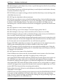
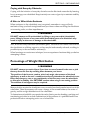
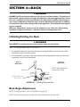
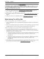
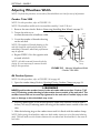
Weight Limitation
InvacareʹsTopEndEverydayandSportSerieswheelchairs(TerminatorTitanium,
TerminatorEveryday,TerminatorBB,X‐TerminatorBB,PaulSchulteSignatureBB,T‐5
TennisElite,X‐Terminatortitanium,X‐terminatorQuadRugbyQRandTransformerAll
Sport)haveaweightlimitationof250lbs(113.4kg).
TerminatorEverydaywheelchairswiththe
heavydutyoptionhaveaweight
limitationof350lbs(158.76kg).
TerminatorTitaniumwheelchairswiththe
heavydutyoptionhaveaweight
limitationof400lbs(181.44kg).
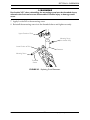
Aweightlimitationlabelisonthecamber
tubeofthechair.
FIGURE 1.1 Weight Capacity Label
Weight Capacity
Label
Camber
Tube

SECTION 2—SAFE HANDLING
Everyday and Sport Series Wheelchairs 18 Part No 1122172
SECTION 2—SAFE HANDLING
“SafetyandHandling”ofthewheelchairrequiresthecloseattentionofthewheelchair
useraswellastheassistant.Thismanualpointsoutthemostcommonproceduresand
techniquesinvolvedinthesafeoperationandmaintenanceofthewheelchair.Itis
importanttopracticeandmasterthesesafetechniquesuntilyouarecomfortablein
manoeuveringaroundthefrequentlyencounteredarchitecturalbarriers.
Usethisinformationonlyasa“basic”guide.Thetechniquesthatarediscussedonthe
followingpageshavebeenusedsuccessfullybymany.
Individualwheelchairusersoftendevelopskillstodealwithdailylivingactivitiesthat
maydifferfromthosedescribedinthismanual.Invacarerecognizesandencourageseach
individualtotrywhatworksbestforhim/herinovercomingarchitecturalobstaclesthat
theymayencounter,however,ALLWARNINGSandCAUTIONSgiveninthismanual
MUSTbefollowed.Techniquesinthismanualareastartingpointforthenewwheelchair
userandassistantwith“safety”asthemostimportantconsiderationforall.
Stability and Balance
WARNING
ALWAYS wear your seat positioning strap. Inasmuch as the SEAT POSITIONING
STRAP is an option on this wheelchair (you may order with or without the seat
positioning strap), Invacare strongly recommends ordering the seat positioning
strap as an additional safeguard for the wheelchair user.
The seat positioning strap is a positioning belt only. It is not designed for use as a
safety device withstanding high stress loads such as auto or aircraft safety belts. If
signs of wear appear, belt MUST be replaced immediately.
Anti-tippers MUST BE attached at all times. Inasmuch as the anti-tippers are an
option on this wheelchair (you may order with or without the anti-tippers), Invacare
strongly recommends ordering the anti-tippers as an additional safeguard for the
wheelchair user.
Toassurestabilityandproperoperationofyourwheelchair,youmustatalltimes
maintainproperbalance.Yourwheelchairhasbeendesignedtoremainuprightand
stableduringnormaldailyactivitiesaslongasyoudonotmovebeyondthecenterof
gravity.
Virtuallyallactivitieswhichinvolvemovementinthewheelchairhaveaneffectonthe
centerofgravity.Invacarerecommendsusingseatpositioningstrapsforadditionalsafety
whileinvolvedinactivitiesthatshiftyourweight.
DONOTleanforwardoutofthewheelchairanyfurtherthanstabilitywillallow.Make
surecastorsarepointingintheforwardpositionwheneveryouleanforward.Thiscanbe
achievedbyadvancingthewheelchairandthenreversingitinastraightline.

SECTION 2—SAFE HANDLING
Part No 1122172 19 Everyday and Sport Series Wheelchairs
Coping with Everyday Obstacles
Copingwiththeirritationofeverydayobstaclescanbealleviatedsomewhatbylearning
howtomanageyourwheelchair.Keepinmind yourcenterofgravitytomaintainstability
andbalance.
A Note to Wheelchair Assistants
Whenassistancetothewheelchairuserisrequired,remembertousegoodbody
mechanics.Keepyourbackstraightandbendyourkneeswhenevertiltingthewheelchair
ortraversingcurbs,orotherimpediments.
WARNING
DO NOT attempt to lift a wheelchair by lifting on any removable (detachable)
parts. Lifting by means of any removable (detachable) parts of a wheelchair may
result in injury to the user or damage to the wheelchair.
Also,beawareofanyremovable(detachable)parts.ThesemustNEVERbeusedtomove
thewheelchairorasliftingsupports,astheymaybeinadvertentlyreleased,resultingin
possibleinjurytotheuserand/orassistant(s).
Whenlearninganewassistancetechnique,haveanexperiencedassistanthelpyoubefore
attemptingitalone.
Percentage of Weight Distribution
WARNING
DO NOT attempt to reach objects if you have to move forward in the seat or pick
them up from the floor by reaching down between your knees.
The position of the footrest, camber tube, back angle, the tautness of the back
upholstery as well as the user's condition are directly related to the wheelchair's sta-
bility. Any change to one or any combination of the five may cause the wheelchair
to decrease in stability. Use EXTREME caution when using a new seating position.
The addition of anti-tippers may be required.
Manyactivitiesrequirethewheelchairownertoreach,bendandtransferinandoutofthe
wheelchair.Thesemovementswillcauseachangetothenormalbalance,thecenterof
gravity,andtheweightdistributionofthewheelchair.
Todetermineandestablishyourparticularsafetylimits,practicebending,reachingand
transferringactivitiesinseveralcombinationsinthepresenceofaqualifiedhealth‐care
professionalbeforeattemptingactiveuseofwheelchair.

SECTION 2—SAFE HANDLING
Everyday and Sport Series Wheelchairs 20 Part No 1122172
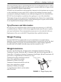
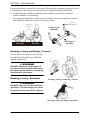
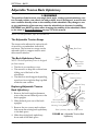
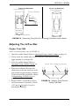
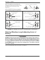
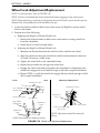
Properpositioningisessentialforyoursafety.Whenreaching,leaning,bendingforward,
itisimportanttousethefrontcastorsasatooltomaintainstabilityandbalance.
• Lengtheningthewheelbasewillincreasethestabilityandmaintainstandard
manoeuverabilityofwheelchair.
• Shorteningthewheelbasewilldecreasethestability,increasethemanoeuverability
anddistributeadditionalweightontotherearwheels.
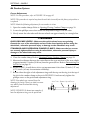
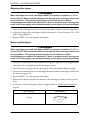
Reaching, Leaning and Bending - Forward
Positionthefrontcastorssothattheyare
extendedasfarforwardaspossibleand
engagewheellocks.
WARNING
DO NOT attempt to reach objects if
you have to move forward in the seat or
pick them up from the floor by reaching
down between your knees.
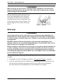
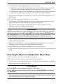
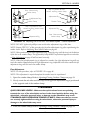
Reaching, Leaning - Backwards
WARNING
DO NOT lean over the top of the back
upholstery. This will change your center
of gravity and may cause you to tip over.
Center of
Gravity
Unoccupied
Occupied
Lengthening the
Wheelbase
Shortening the
Wheelbase
Rear of
Wheelchair
Reaching, Leaning, and Bending - Forward
Reaching, Leaning, and Bending - Backwards
Page is loading ...
Page is loading ...
Page is loading ...
Page is loading ...
Page is loading ...
Page is loading ...
Page is loading ...
Page is loading ...
Page is loading ...
Page is loading ...
Page is loading ...
Page is loading ...
Page is loading ...
Page is loading ...
Page is loading ...
Page is loading ...
Page is loading ...
Page is loading ...
Page is loading ...
Page is loading ...
Page is loading ...
Page is loading ...
Page is loading ...
Page is loading ...
Page is loading ...
Page is loading ...
Page is loading ...
Page is loading ...
Page is loading ...
Page is loading ...
Page is loading ...
Page is loading ...
Page is loading ...
Page is loading ...
Page is loading ...
Page is loading ...
Page is loading ...
Page is loading ...
Page is loading ...
Page is loading ...
Page is loading ...
Page is loading ...
Page is loading ...
Page is loading ...
Page is loading ...
Page is loading ...
Page is loading ...
Page is loading ...
Page is loading ...
Page is loading ...
Page is loading ...
Page is loading ...
Page is loading ...
Page is loading ...
Page is loading ...
Page is loading ...
-
 1
1
-
 2
2
-
 3
3
-
 4
4
-
 5
5
-
 6
6
-
 7
7
-
 8
8
-
 9
9
-
 10
10
-
 11
11
-
 12
12
-
 13
13
-
 14
14
-
 15
15
-
 16
16
-
 17
17
-
 18
18
-
 19
19
-
 20
20
-
 21
21
-
 22
22
-
 23
23
-
 24
24
-
 25
25
-
 26
26
-
 27
27
-
 28
28
-
 29
29
-
 30
30
-
 31
31
-
 32
32
-
 33
33
-
 34
34
-
 35
35
-
 36
36
-
 37
37
-
 38
38
-
 39
39
-
 40
40
-
 41
41
-
 42
42
-
 43
43
-
 44
44
-
 45
45
-
 46
46
-
 47
47
-
 48
48
-
 49
49
-
 50
50
-
 51
51
-
 52
52
-
 53
53
-
 54
54
-
 55
55
-
 56
56
-
 57
57
-
 58
58
-
 59
59
-
 60
60
-
 61
61
-
 62
62
-
 63
63
-
 64
64
-
 65
65
-
 66
66
-
 67
67
-
 68
68
-
 69
69
-
 70
70
-
 71
71
-
 72
72
-
 73
73
-
 74
74
-
 75
75
-
 76
76


Invacare Titanium Heavy Duty Owner's Operator And Maintenance Manual
- Category
- Cable clamps
- Type
- Owner's Operator And Maintenance Manual
Ask a question and I''ll find the answer in the document
Finding information in a document is now easier with AI
Related papers
-
Invacare Top End T-3 Tennis Adjustable Operating And Maintenance Manual
-
-
-
-
-
-
-
-
-
Other documents
-
Razor W15128001049 User manual
-
Vestil AFT-xx Owner's manual
-
AmeriHome 802498 Operating instructions
-
MooreCo Tablet Side Table Assembly Instructions
-
BakkerElkhuizen BNEFRB952 Datasheet
-
-
OTC 5750 Operating instructions
-
-
 Furniture of America IDF-6957LG-CNR Installation guide
-
RGK Octane FX User manual
