Page is loading ...

Owner's Operator And Maintenance Manual
®
Terminator
SS
DEALER: THIS MANUAL MUST BE GIVEN TO THE USER
OF THE WHEELCHAIR.
USER: BEFORE USING THIS WHEELCHAIR, READ THIS
MANUAL AND SAVE FOR FUTURE REFERENCE.

Terminator SS 2 Part No. 1052712 Rev D
SPECIAL NOTES
WARNING/CAUTION notices as used in this manual apply to hazards or
unsafe practices which could result in personal injury or property damage.
NOTICE
THE INFORMATION CONTAINED IN THIS DOCUMENT IS SUBJECT
TO CHANGE WITHOUT NOTICE.
As a manufacturer of wheelchairs, Invacare endeavors to supply a wide
variety of wheelchairs to meet many needs of the end user. However, final
selection of the type of wheelchair to be used by an individual rests solely
with the user and his/her healthcare professional capable of making such a
selection.
WHEELCHAIR TIE-DOWN RESTRAINTS AND SEAT POSITIONING
STRAPS
Invacare recommends that wheelchair users NOT be transported in vehicles
of any kind while in wheelchairs. As of this date, the Department of
Transportation has not approved any tie-down systems for transportation of
a user while in a wheelchair, in a moving vehicle of any type.
It is Invacares position that users of wheelchairs should be transferred into
appropriate seating in vehicles for transportation and use be made of the
restraints made available by the auto industry. Invacare cannot and does not
recommend any wheelchair transportation systems.
AS REGARDS RESTRAINTS - SEAT POSITIONING STRAPS - IT IS THE
OBLIGATION OF THE DME DEALER, THERAPISTS AND OTHER
HEALTHCARE PROFESSIONALS TO DETERMINE IF A SEATING
POSITIONING STRAP IS REQUIRED TO ENSURE THE SAFE OPERA-
TION OF THIS EQUIPMENT BY THE USER. SERIOUS INJURY CAN
OCCUR IN THE EVENT OF A FALL FROM A WHEELCHAIR.
SPECIAL NOTES
WARNING
DO NOT OPERATE THIS EQUIPMENT WITHOUT FIRST
READING AND UNDERSTANDING THIS MANUAL. IF
YOU ARE UNABLE TO UNDERSTAND THE WARNINGS,
CAUTIONS AND INSTRUCTIONS, CONTACT YOUR
INVACARE DEALER OR INVACARE CUSTOMER SUPPORT
AT (800) 532-8677 BEFORE ATTEMPTING TO USE THIS
EQUIPMENT - OTHERWISE INJURY AND/OR EQUIPMENT
DAMAGE MAY RESULT.
SAVE THESE INSTRUCTIONS
SPECIAL NOTES

Part No. 1052712 Rev D 3 Terminator SS
TABLE OF CONTENTS
TABLE OF CONTENTS
TABLE OF CONTENTS
SPECIAL NOTES................................................................................ 2
SPECIFICATIONS .............................................................................. 5
SECTION 1 - GENERAL GUIDELINES .................................................. 6
STABILITY ....................................................................................................................................................... 6
OPERATING INFORMATION ................................................................................................................. 6
TIRE PRESSURE AND INFORMATION ................................................................................................. 8
WEIGHT TRAINING ................................................................................................................................... 8
WEIGHT LIMITATION ............................................................................................................................... 8
SAFETY/HANDLING OF WHEELCHAIRS ............................................................................................ 9
SECTION 2 - SAFETY INSPECTION .................................................. 14
SAFETY INSPECTION CHECKLIST .....................................................................................................14
TROUBLESHOOTING ............................................................................................................................. 15
MAINTENANCE ........................................................................................................................................ 15
SECTION 3 - BACK ......................................................................... 17
BACK ANGLE ADJUSTMENT ............................................................................................................... 17
FOLDING/UNFOLDING THE BACK .................................................................................................. 19
ADJUSTING/REPLACING BACK UPHOLSTERY............................................................................. 19
BACK HEIGHT ADJUSTMENT (ADJUSTABLE BACKS ONLY) .................................................. 23
SECTION 4 - SEAT .......................................................................... 24
REPLACING TOP END SEAT UPHOLSTERY ................................................................................... 24
REPLACING CUSTOM MANUAL SCREW ON SEAT UPHOLSTERY ...................................... 25
SECTION 5 - WHEELS ...................................................................... 26
REMOVING/INSTALLING REAR WHEELS........................................................................................ 26
ADJUSTING QUICK-RELEASE AXLES ................................................................................................ 27
INSTALLING QUAD-RELEASE AXLES ............................................................................................... 28
ADJUSTING QUAD-RELEASE HANDLES ......................................................................................... 28
HANDRIM REPLACEMENT ................................................................................................................... 29
REPAIRING/REPLACING REAR WHEEL, TIRE/TUBE .................................................................... 30
OPENING/CLOSING CLAMPS ............................................................................................................. 30
ADJUSTING REAR WHEEL CAMBER ................................................................................................. 32
DETERMINING TOE IN/TOE OUT ..................................................................................................... 33
ADJUSTING TOE IN/TOE OUT ........................................................................................................... 34
ADJUSTING WHEELBASE LENGTH (ADJUSTING CENTER OF GRAVITY) ......................... 37
ADJUSTING WHEELBASE WIDTH ..................................................................................................... 38
REPLACING AXLE TUBE ........................................................................................................................ 39
ADJUSTING THE AXLE TUBE .............................................................................................................. 40
REPLACING/ADJUSTING CASTERS ................................................................................................... 43
ADJUSTING FRONT CASTER HEIGHT ............................................................................................. 44
WHEEL LOCK ADJUSTMENT/REPLACEMENT .............................................................................. 45

Terminator SS 4 Part No. 1052712 Rev D
TABLE OF CONTENTS
TABLE OF CONTENTS
SECTION 6 - FOOTREST/ANTI-TIPPER ............................................. 46
ADJUSTING/REPLACING STANDARD FOOTREST ...................................................................... 46
INSTALLING/ADJUSTING OPTIONAL CLAMP ON RAISED FOOTREST ............................. 47
INSTALLING/ADJUSTING OPTIONAL A4 FOOTREST ............................................................... 47
ANTI-TIPPER REPLACEMENT/ADJUSTMENT ................................................................................. 49
SECTION 7 - SUSPENSION ............................................................... 50
ELASTOMERS AND SUSPENSION ...................................................................................................... 50
REPLACING REAR ELASTOMERS ........................................................................................................ 50
REPLACING FRONT ELASTOMERS ................................................................................................... 52
REMOVING/INSTALLING/REPLACING SUSPENSION TUBES ................................................... 53
ADJUSTING SEAT-TO-FLOOR HEIGHT ........................................................................................... 54
REPOSITIONING THE AXLE TUBE .................................................................................................... 55
REPOSITIONING QUICK RELEASE LEVERS..................................................................................... 57
LIMITED WARRANTY ..................................................................... 59

Part No. 1052712 Rev D 5 Terminator SS
SPECIFICATIONS
SPECIFICATIONS
NOTE: All specifications are approximate.
SPECIFICATIONS
TERMINATOR SS
Frame: Rigid - with Rear Suspension - 4130 Chrome-moly
Seat Width: 12-20-inches - Outside to Outside of SEAT FRAME in 1-inch increments.
Seat Depth: 14 to 18-inches (15-inch Standard)
Seat-to-Floor: Front - 17 to 21-inches
Rear -14 to 21-inches
Back Style: Fixed (Standard), Fold Down
Back Height
Fixed: 8 to 16-inches
Adjustable: Low - 11 to 14-inches in 1-inch increments.
Medium - 14 to 18-inches in 1-inch increments.
Tall - 16 to 20-inches in 1-inch increments.
Back Angle: 0°, 3°, 5° or 7°
Rear-Front Caster Distance: 19 to 21-inches
(measured from outside of back of frame to center of front caster housing)
Front Caster to Footplate
Distance: 3 to 5-inches
Foot Width: 9 to 12-inches (average is 10-inches)
(measured between front of footrest bars)
Footrest: Tubular: 4-inch Height Adjustable (Standard)
Side - Wheel Clearance: Adjustable 1/2 to 1-1/2-inches
Rear Axle: Adjustable Axle Position, Quick or Quad-Release
Rear Wheel Camber
Camber Tube 2000: 0°, 3°, 6°, 12°
A4 Camber System: 0°, 3°, 6°, 9°, 12°
Rear Wheel Sizes: 24, 25, 26-inch (24-inch Standard)
Double walled rim high flange hub (Standard)
Available Tires and Wheels: 24-inch: Primo 25-540 (Standard), 24x1-3/8-inch, Knobby, Spinergy®, KIK®
25-inch: Primo 25-559 (Standard), Knobby, Spinergy, KIK
26-inch: Primo 25-590 (Standard), Spinergy
Handrims: Aluminum Welded Tab (Standard), Plastic Coated, Dual Grip®
Wheel Locks: High Mount, Low Mount (Standard)
Front Forks: Suspension Fork
Caster Size: 3, 4 and 5-inch
Back Upholstery: U240 Black - Adjustable Tension
Weight: 24 pounds
Shipping Weight*: 40 pounds
*NOTE: 15 x 15-inch seat frame with complete package.

Terminator SS 6 Part No. 1052712 Rev D
Section 1 - General Guidelines - includes the following:
Stability
Operating Information
Tire Pressure and Information
Weight Training
Weight Limitation
Safety/Handling of Wheelchairs
GENERAL GUIDELINESSECTION 1
GENERAL GUIDELINES
STABILITYSTABILITY
STABILITYSTABILITY
STABILITY
STABILITY WARNING
The position of the footrest, camber tube, back angle, the tautness of the back
upholstery as well as the user's condition are directly related to the wheelchair's
stability. Any change to one (1) or any combination of the five (5) may cause the
wheelchair to decrease in stability. Use EXTREME caution when using a new
seating position. The addition of anti-tippers may be required .
NOTE: When changes to the left hand column occur, follow across the chart and refer to the
procedure to maintain the proper stability, safety and handling of the wheel chair.
OPERATING INFORMATION
WARNING
To determine and establish your particular safety limits, practice bending,
reaching and transferring activities in several combinations in the presence of a
qualified healthcare professional BEFORE attempting active use of the wheelchair.
DO NOT attempt to reach objects if you have to move forward in the seat.
DO NOT attempt to reach objects if you have to pick them up from the
floor by reaching down between your knees.
DO NOT lean over the top of the back upholstery to reach objects from
behind as this may cause the wheelchair to tip over.
DO NOT shift your weight or sitting position toward the direction you
are reaching as the wheelchair may tip over.
Footrest Position
Camber Tube
Back Angle
Back Upholstery
User Condition
Footrest Position
Camber Tube
Back Angle
Back Upholstery
User Condition

Part No. 1052712 Rev D 7 Terminator SS
WARNING
DO NOT tip the wheelchair without assistance.
DO NOT use an escalator to move a wheelchair between floors. Serious
bodily injury may occur. Before attempting to transfer in or out of the
wheelchair, every precaution should be taken to reduce the gap distance.
Turn both casters toward the object you are transferring onto. Also be
certain the wheel locks are engaged to prevent the wheels from moving.
DO NOT operate on roads, streets or highways.
DO NOT climb, go up or down ramps or traverse slopes greater than 9
o
.
DO NOT attempt to move up or down an incline with a water, ice or oil film.
DO NOT attempt to ride over curbs or obstacles. Doing so may cause your
wheelchair to turn over and cause bodily harm or damage to the wheelchair.
DO NOT use ANY parts, accessories, or adapters other than those authorized
by Invacare. Otherwise, the warranty is void.
DO NOT attempt to lift the wheelchair by any removable (detachable)
parts. Lifting by means of any removable (detachable) parts of a wheelchair
may result in injury to the user or damage to the wheelchair.
DO NOT stand on the frame of the wheelchair.
Check ALL allen screws that secure the footrest/raised footrest system to
the chair frame BEFORE using the wheelchair. ESPECIALLY if engaging in
ANY contact sport.
Anti-tippers MUST BE attached at all times. Inasmuch as the anti-tippers are
an option on this wheelchair (you may order with or without the anti-tippers),
Invacare strongly recommends ordering the anti-tippers as an additional
safeguard for the wheelchair user.
Unless otherwise noted, all service and adjustments should be performed
while the wheelchair is unoccupied.
DO NOT use the footplate as a platform when getting in or out of the
wheelchair.
ALWAYS wear your seat positioning strap. Inasmuch as the SEAT
POSITIONING STRAP is an option on this wheelchair (you may order with or
without the seat positioning strap), Invacare strongly recommends ordering
the seat positioning strap as an additional safeguard for the wheelchair user.
ALWAYS use the handrims for self-propulsion. Inasmuch as the
HANDRIMS are an option on this wheelchair (you may order with or
without the handrims), Invacare strongly recommends ordering the
handrims as an additional safeguard for the wheelchair user.
GENERAL GUIDELINES SECTION 1
GENERAL GUIDELINES

Terminator SS 8 Part No. 1052712 Rev D
GENERAL GUIDELINESSECTION 1
GENERAL GUIDELINES
TIRE PRESSURE AND INFORMATION
WARNING
DO NOT use your wheelchair unless it has the proper tire pressure (p.s.i.).
DO NOT overinflate the tires. Failure to follow these suggestions may cause
the tire to explode and cause bodily harm. The recommended tire pressure
is on the sidewall of the tire.
Replacement of the tire or tube MUST be performed by a qualified technician.
WEIGHT TRAINING
WARNING
Invacare DOES NOT recommend the use of its wheelchairs as a weight
training apparatus. Invacare wheelchairs have NOT been designed or tested
as a seat for any kind of weight training. If occupant uses said wheelchair as a
weight training apparatus, Invacare shall NOT be liable for bodily injury and
the warranty is void.
WEIGHT LIMITATION
Invacare's Top End Terminator SS wheelchairs have a weight limitation
of 250 lbs.

Part No. 1052712 Rev D 9 Terminator SS
SAFETY/HANDLING OF WHEELCHAIRS
Safety and Handling of the wheelchair requires the close attention of the wheelchair
user as well as the assistant. This manual points out the most common procedures and
techniques involved in the safe operation and maintenance of the wheelchair. It is
important to practice and master these safe techniques until you are comfortable in
maneuvering around the frequently encountered architectural barriers.
Use this information only as a basic guide. The techniques that are discussed on the
following pages have been used successfully by many.
Individual wheelchair users often develop skills to deal with daily living activities that
may differ from those described in this manual. Invacare recognizes and encourages each
individual to try what works best for him/her in overcoming architectural obstacles that
they may encounter, however, ALL WARNINGS and CAUTIONS given in this manual
MUST be followed. Techniques in this manual are a starting point for the new
wheelchair user and assistant, with safety as the most important consideration for all.
STABILITY AND BALANCE
WARNING
ALWAYS wear your seat positioning strap. Inasmuch as the SEAT
POSITIONING STRAP is an option on this wheelchair (You may order with
or without the seat positioning strap), Invacare strongly recommends ordering
the seat positioning strap as an additional safeguard for the wheelchair user.
Anti-tippers MUST BE attached at all times. Inasmuch as the anti-tippers are
an option on this wheelchair (You may order with or without the anti-tippers),
Invacare strongly recommends ordering the anti-tippers as an additional
safeguard for the wheelchair user.
To assure stability and proper operation of your wheelchair, you must at all times maintain
proper balance. Your wheelchair has been designed to remain upright and stable during
normal daily activities as long as you do not move beyond the center of gravity.
Virtually all activities which involve movement in the wheelchair have an effect on the
center of gravity. Invacare recommends using seat positioning straps for additional safety
while involved in activities that shift your weight.
DO NOT lean forward out of the wheelchair any further than stability will allow. Make
sure casters are pointing in the forward position whenever you lean forward. This can
be achieved by advancing the wheelchair and then reversing it in a straight line.
COPING WITH EVERYDAY OBSTACLES
Coping with the irritation of everyday obstacles can be alleviated somewhat by learning how to
manage your wheelchair. Keep in mind your center of gravity to maintain stability and balance.
A NOTE TO WHEELCHAIR ASSISTANTS
When assistance to the wheelchair user is required, remember to use good body mechanics.
Keep your back straight and bend your knees whenever tilting the wheelchair or traversing
curbs, or other impediments.
GENERAL GUIDELINES SECTION 1
GENERAL GUIDELINES

Terminator SS 10 Part No. 1052712 Rev D
GENERAL GUIDELINESSECTION 1
GENERAL GUIDELINES
WARNING
Do not attempt to lift a wheelchair by lifting on any removable (detachable)
parts. Lifting by means of any removable (detachable) parts of a wheelchair
may result in injury to the user or damage to the wheelchair.
Also, be aware of any removable (detachable) parts. These must NEVER be used to
move the wheelchair or as lifting supports, as they may be inadvertently released,
resulting in possible injury to the user and/or assistant(s).
When learning a new assistance technique, have an experienced assistant help you
before attempting it alone.
PERCENTAGE OF WEIGHT DISTRIBUTION
WARNING
DO NOT attempt to reach objects if you have to move forward in the seat
or pick them up from the floor by reaching down between your knees.
The position of the footrest, camber tube, back angle, the tautness of the back
upholstery as well as the user's condition are directly related to the wheelchair's
stability. Any change to one (1) or any combination of the five (5) may cause the
wheelchair to decrease in stability. Use EXTREME caution when using a new
seating position. The addition of anti-tippers may be required .
Many activities require the wheelchair
owner to reach, bend and transfer in and
out of the wheelchair. These movements
will cause a change to the normal balance,
the center of gravity, and the weight
distribution of the wheelchair.
To determine and establish your particular
safety limits, practice bending, reaching and
transferring activities in several
combinations in the presence of a qualified
health-care professional BEFORE
attempting active use of wheelchair.
Proper positioning is essential for your
safety. When reaching, leaning, bending
forward, it is important to use the front
casters as a tool to maintain stability and
balance.
LENGTHENING THE WHEELBASE
will increase the stability and maintain
standard maneuverability of wheelchair.
SHORTENING THE WHEELBASE
will decrease the stability, increase the
maneuverability and distribute additional
weight onto the rear wheels.
LENGTHENING
SHORTENING
UNOCCUPIED OCCUPIED
Center of Gravity

Part No. 1052712 Rev D 11 Terminator SS
Reaching, Leaning and Bending - Forward.
Position the front casters so that they are
extended as far forward as possible and
engage wheel locks.
WARNING
DO NOT attempt to reach objects
if you have to move forward in the
seat or pick them up from the floor
by reaching down between your
knees.
Reaching, Leaning - Backwards.
WARNING
DO NOT lean over the top of the
back upholstery. This will change
your center of gravity and may
cause you to tip over.
REACHING, LEANING AND
BENDING - FORWARD
REACHING, LEANING -
BACKWARDS
GENERAL GUIDELINES SECTION 1
GENERAL GUIDELINES
TIPPING
WARNING
DO NOT tip the wheelchair without assistance.
DO NOT let the wheelchair drop the last few inches to the ground.
This could result in injury to the occupant.
When tipping the wheelchair, an assistant should grasp the back of the wheelchair on a
non-removable (non-detachable) part. Inform the wheelchair occupant before tilting the
wheelchair and remind him/her to lean back. Be sure the occupants feet and hands are
clear of all wheels and/or pinch points. Apply a continuous motion until the balance
point is achieved. At this point, the assistant will feel a difference in the weight
distribution. Turn the wheelchair in the desired direction if necessary. Slowly lower the
wheelchair in one continuous movement.

Terminator SS 12 Part No. 1052712 Rev D
GENERAL GUIDELINESSECTION 1
GENERAL GUIDELINES
TIPPING - CURBS:
WARNING
Invacare does not recommend that sport wheelchairs be used where
traversing curbs present an obstacle. Possible injury to occupant and/or
assistant(s) can occur. Transfer to an everyday use wheelchair is
recommended if any such obstacles may be encountered.
After mastering the techniques of tipping the wheelchair, use the following method to tackle
curbs, short stairs, etc.
Turn the anti-tippers, if equipped, so the wheels are facing UP. Unless the first assistant has
exceptional upper body strength, it is recommended that two (2) assistants perform this
operation. The second assistant should be positioned at the front of the wheelchair lifting
upward on a non-removable (non-detachable) part of the wheelchair frame when lifting the
wheelchair and stabilizing the wheelchair when the wheelchair is being lowered to the ground.
The first assistant should stand on the sidewalk and turn the wheelchair so that the rear wheels
are against the curb. The wheelchair should be tilted back to the balance point and, in one
continuous upward movement, the rear wheels should be pulled up and over the curb.
DO NOT return the front casters to the ground until the wheelchair has been pulled backward
far enough for the front casters to clear the edge of the curb.
WARNING
When lowering the front casters of the wheelchair, DO NOT let the
wheelchair drop the last few inches to the ground. This could result in
injury to the occupant and/or damage to the wheelchair.
Roll the wheelchair backward and
SLOWLY lower the wheelchair in one
continuous movement. DO NOT let the
wheelchair drop the last few inches to the
ground. This could result in injury to the
occupant. Turn the anti-tippers so the
wheels are facing DOWN.
STAIRWAYS
WARNING
Concerning stairway access; Invacare does not recommend that these
wheelchairs be transported up or down stairways with occupant in the
wheelchair. Possible injury to occupant and/or assistant(s) can occur.
Transfer to an everyday use wheelchair is recommended.
DO NOT attempt to lift the wheelchair by any removable (detachable)
parts. Lifting by means of any removable (detachable) parts of a wheelchair
may result in injury to the user or damage to the wheelchair.
Extreme caution is advised when it is necessary to move an occupied
wheelchair up or down a stairway. Invacare recommends that, if possible, the
user be removed from the wheelchair prior to moving. Invacare recommends
using two (2) assistants and making thorough preparations. Make sure to use
ONLY secure, non-detachable parts for hand-held supports.

Part No. 1052712 Rev D 13 Terminator SS
Follow this procedure for moving the wheelchair between floors when an elevator is
NOT available:
1. If equipped, turn the anti-tippers UP. Refer to SECTION 6 in this manual.
2. After the wheelchair has been tilted back to the balance point, one assistant (in the
rear) backs the wheelchair up against the first step, while securely grasping a non-
removable (non-detachable) part of the wheelchair for leverage.
3. The second assistant, with a firm hold on a non-detachable part of the framework,
lifts the wheelchair up and over the stair and steadies it as the first assistant places
one foot on the next stair and repeats procedure.
4. The wheelchair should not be lowered until the last stair has been negotiated and it
has been rolled away from the stairway.
5. If equipped, turn the anti-tippers DOWN. Refer to SECTION 6 in this manual.
ESCALATORS? SORRY!
DO NOT use an escalator to move a wheelchair between floors. Serious
bodily injury may occur.
TRANSFERRING TO AND FROM OTHER SEATS
WARNING
BEFORE attempting to transfer in or out of the wheelchair, every precaution
should be taken to reduce the gap distance. Turn both casters parallel to the
object you are transferring onto. Also be certain the wheel locks are engaged
to help prevent the wheels from moving.
CAUTION
When transferring, position yourself as far back as possible in the seat. This
will prevent damaged upholstery and the possibility of the wheelchair
tipping forward.
NOTE: This activity may be performed independently provided you have adequate mobility and
upper body strength.
Position the wheelchair as close as
possible along side the seat to which you
are transferring, with the front casters
parallel to it. Remove the armrest, if
installed. Engage wheel locks. Shift body
weight into seat with transfer.
During independent transfer, little or no
seat platform will be beneath you. Use a
transfer board if at all possible.
GENERAL GUIDELINES SECTION 1
GENERAL GUIDELINES

Terminator SS 14 Part No. 1052712 Rev D
SAFETY INSPECTIONSECTION 2
SAFETY INSPECTION
Section 2 - Safety Inspection - includes the following:
Safety Inspection Checklist
Troubleshooting
Maintenance
NOTE: Every six (6) months, take your wheelchair to a qualified technician for a thorough inspection
and servicing. Regular cleaning will reveal loose or worn parts and enhance the smooth operation
of your wheelchair. To operate properly and safely, your wheelchair must be cared for just like any
other vehicle. Routine maintenance will extend the life and efficiency of your wheelchair. Clean
upholstery with mild soap and water or spray disinfectant using a sponge. DO NOT use bleach or
wash in a washing machine.
SAFETY INSPECTION CHECKLIST
Initial adjustments should be made to suit your personal body structure and preference.
Thereafter follow these maintenance procedures:
ITEM INITIALLY INSPECT/ INSPECT/ INSPECT/
ADJUST ADJUST ADJUST
WEEKLY MONTHLY PERIODICALLY
GENERAL
Wheelchair rolls straight (no excessive drag/pull to one side). X X
WHEEL LOCKS
Do not interfere with tires when rolling. X X
Pivot points free of wear and looseness. X X
Wheel locks easy to engage. X X
SEAT AND BACK UPHOLSTERY
Inspect for rips or sagging. X X
Inspect fastening flaps to ensure they securely latch. X X
REAR WHEELS
Quick release axles and camber inserts are clean. X X
Adjustable Axle Position Camber Bar is securely tightened. X X X
Quick/Quad release axles lock properly. X X
No excessive side movement or binding when lifted and spun. X X
HANDRIMS
Inspect for signs of rough edges or peeling. X X
SPOKES
Inspect for bent or broken spokes. X X
All spokes uniformly tight. X X
FRONT CASTER
Inspect wheel/fork assembly for proper tension by spinning
caster; caster should come to a gradual stop. X X
Loosen/tighten locknut if wheel wobbles noticeably or binds
to a stop. X X
Wheel bearings are clean and free of moisture. X X X
CAUTION: As with any vehicle, the wheels and
tires should be checked periodically for cracks and
wear, and should be replaced if damaged.
TIRES
Inspect for flat spots and wear. X X
If pneumatic tires check for proper inflation. X X
CAUTION: As with any vehicle, the wheels and
tires should be checked periodically for cracks and
wear, and should be replaced if damaged.
ELASTOMERS
Inspect elastomers for proper lubrication. X
CLEANING
Clean upholstery and armrests. X X

Part No. 1052712 Rev D 15 Terminator SS
TROUBLESHOOTING
SAFETY INSPECTION SECTION 2
MAINTENANCE
MAINTENANCE SAFETY PRECAUTIONS
WARNING
After ANY adjustments, repair or service and BEFORE use, make sure all
attaching hardware is tightened securely - otherwise injury or damage may
result.
CAUTION
DO NOT overtighten hardware attaching to the frame. This could cause
damage to the frame tubing.
SUGGESTED MAINTENANCE PROCEDURES
1. Before using your wheelchair, make sure all nuts and bolts are tight. Check all parts
for damage or wear and replace. Check all parts for proper adjustment.
2. Keep quick/quad-release axles free of dirt and lint to ensure positive locking and
proper operation. Refer to ADJUSTING QUICK-RELEASE AXLES or ADJUSTING
QUAD-RELEASE HANDLES in SECTION 5 of this manual.
WARNING
DO NOT use WD-40®, 3-in-1 oil®, or other penetrating lubricants on
quick-release axles or camber inserts. Otherwise, binding and/or damage
to the wheelchair may occur.
3. Clean quick-release axles and camber inserts once (1) a week with a Teflon®
lubricant.
WARNING
DO NOT use your wheelchair unless it has the proper tire pressure
(p.s.i.).
DO NOT overinflate the tires. Failure to follow these suggestions may
cause the tire to explode and cause bodily harm. The recommended tire
pressure is on the sidewall of the tire.
4. Recommended tire pressure (p.s.i.) is listed on the sidewall of the tire.
SAFETY INSPECTION
CHAIR CHAIR SLUGGISH CASTER SQUEAKS LOOSENESS SOLUTIONS
VEERS VEERS TURN OR FLUTTERS AND IN CHAIR
RIGHT LEFT PERFORMANCE RATTLES
XX X X Check tires for correct
and equal pressure.
XXXXCheck for loose stem nuts.
XXCheck spokes and nipples.
XX X Check that both casters
contact the ground at the
same time.

Terminator SS 16 Part No. 1052712 Rev D
CAUTION
As with any vehicle, the wheels and tires should be checked
periodically for cracks and wear, and should be replaced if damaged.
5. The wheels, casters and tires should be checked periodically for cracks and
wear, and should be replaced when necessary. Contact a qualified technician or
Invacare customer support at the telephone numbers on the back of this manual.
6. Regularly check for loose spokes in the rear wheels. If loose, have them adjusted.
Contact a qualified technician or Invacare customer support at the telephone
numbers on the back of this manual.
7. Periodically check handrims to ensure they are secured to the rear wheels.
Refer to HANDRIM REPLACEMENT in SECTION 5 of this manual.
8. Periodically adjust wheel locks as tires wear. Refer to
WHEEL LOCK
ADJUSTMENT/REPLACEMENT in SECTION 5 of this manual.
9. Periodically check caster wheel bearings to make sure they are clean and free
from moisture. Use a Teflon lubricant if necessary.
10. Periodically lubricate the inside of the elastomers and the shaft of the hex bolt
that secures the elastomers to the suspension tube with a silicone based
lubricant.
11. Check Upholstery for sagging, rips or tears.
12. Clean Upholstery with mild soap and water.
SAFETY INSPECTIONSECTION 2
SAFETY INSPECTION

Part No. 1052712 Rev D 17 Terminator SS
SECTION 3BACK
WARNING
ALWAYS perform this procedure in the presence of an assistant. The
position of the footrest, camber tube, back angle, the tautness of the back
upholstery as well as the user's condition are directly related to the
wheelchairs stability. Any change to one (1) or any combination of the
five (5) may cause the wheelchair to decrease in stability. Use EXTREME
caution when using a new seating position. The addition of anti-tippers
may be required .
After ANY adjustments, repair or service and BEFORE use, make sure all
attaching hardware is tightened securely - otherwise injury or damage
may result.
BACK ANGLE ADJUSTMENT (FIGURE 1)
NOTE: This procedure is for fold down back chairs only.
NOTE: DO NOT remove the hex screws that secure the back angle bracket to the chair frame
and back cane.
NOTE: Perform procedure to both sides at the same time.
1. Loosen the locknuts and hex screws that secure the back angle bracket to the chair
frame and the back cane.
2. Loosen the TOP hex screw locknut and slide the TOP hex screw away from the
back angle mounting bracket to adjust the cam.
3. Adjust back canes to approximate back angle required.
4. Adjust cam to achieve desired position.
NOTE: An indexing notch has been put on the adjustment cam to help determine cam position
for desired back angle adjustment.
5. Reassemble and torque hex screws to 960-1020 inch-pounds (80-85 foot-pounds).
NOTE: As shown in FIGURE 1, the adjustment cam can be rotated to several different positions
thus changing the overall back angle relative to the seat rail.
Section 3 - Back - includes the following:
Back Angle Adjustment
Folding/Unfolding the Back
Adjusting/Replacing Back Upholstery
Back Height Adjustment (Adjustable Backs Only)
BACK

Terminator SS 18 Part No. 1052712 Rev D
BACKSECTION 3
FIGURE 1 - BACK ANGLE ADJUSTMENT
BACK
73° BACK ANGLE TO SEAT RAIL77° BACK ANGLE TO SEAT RAIL
84° BACK ANGLE TO SEAT RAIL
94° BACK ANGLE TO SEAT RAIL
85° BACK ANGLE TO SEAT RAIL
90° BACK ANGLE TO SEAT RAIL
Back Cane
Indexing Notch
Cam
Back Angle
Bracket
Seat Rail
TOP Hex
Screw and
Locknut
Back
Cane
Indexing Notch
Cam
Back Angle Bracket
Seat Rail
TOP Hex
Screw and
Locknut
Back Cane
Indexing Notch
Cam
Back Angle
Bracket
Seat Rail
TOP Hex
Screw and
Locknut
Back Cane
Indexing Notch
Cam
Back Angle Bracket
Seat Rail
TOP Hex Screw and
Locknut
Back Cane
Indexing
Notch
Cam
Back Angle
Bracket
Seat Rail
TOP Hex
Screw and
Locknut
Back Cane
Indexing Notch
Cam
Back Angle Bracket
Seat Rail
TOP Hex Screw and
Locknut

Part No. 1052712 Rev D 19 Terminator SS
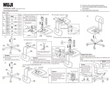
FOLDING/UNFOLDING THE BACK (FIGURE 2)
NOTE: This procedure is for folding back chairs only.
WARNING
Back MUST be locked securely in place before using the chair.
1. Lift up on the back and pull towards the rear of the chair until it locks into place.
2. To fold the back, pull up on the black nylon cord and push the back forward
SECTION 3BACK
BACK
Back Cane
Seat Frame
FIGURE 2 - FOLDING/UNFOLDING THE BACK
ADJUSTING/REPLACING BACK UPHOLSTERY
TOP END BACK UPHOLSTERY (FIGURE 3)
WARNING
The back flaps and center upholstery MUST be replaced if hook and loop
fastener is worn or DOES NOT secure the flaps to the back center upholstery.
If hook and loop fastener is NOT secure, serious injury may result.
Adjusting Top End Back Upholstery.
1. Unlatch the two (2) fastening flaps that secure the top of the back upholstery to the
back canes.
2. Align the top of the back upholstery with the fastening flaps ensuring the top of the
back upholstery is even with the top of the back canes.
3. Adjust to the desired tautness.
TIGHTER back upholstery will increase the stability and maintain normal maneuverability
of the wheelchair because the user is pushed forward in the wheelchair slightly.
LOOSER back upholstery will increase the maneuverability and make the wheelchair
more unstable because additional weight is being distributed onto the rear wheels.
4. Securely latch back upholstery to the fastening flaps.

Terminator SS 20 Part No. 1052712 Rev D
BACKSECTION 3
BACK
Replacing Top End Back Upholstery.
1. Unlatch the two (2) fastening flaps that secure the top of the back upholstery to the
back canes.
2. Remove the fastening flaps from the back canes by lifting straight up.
3. Remove the seat cushion.
4. Separate the bottom of the back upholstery from either the underside or top of the
seat upholstery (depending on back style).
5. Install the NEW fastening flaps onto the back canes.
NOTE: The fastening flap with logo is for the left back cane.
NOTE: Right and left is determined by sitting in the wheelchair.
6. Securely latch the bottom of the back upholstery to the fasteners on either the
underside or top of the seat upholstery (depending on back style).
7. Adjust the NEW back upholstery to the desired tautness. Refer to ADJUSTING
TOP END BACK UPHOLSTERY in this section of the manual.
FIGURE 3 - ADJUSTING/REPLACING BACK UPHOLSTERY -
TOP END BACK UPHOLSTERY
Fastening
Flap with
Logo
Seat
Upholstery
Back Upholstery
Wheelchair
Frame
Fastening Flap
Bottom of Back
Upholstery
/