
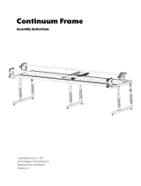
Copyright January 1, 2016
Jim M. Bagley, GraceWood, Inc
(Reproduction Prohibited)
Version 2.4
Batting Rail Instructions
Continuum Frame
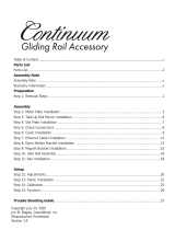
Table of Contents ...................................................................................................................... i
Parts List
Parts List..................................................................................................................................ii
Setup & Assembly
Step 1: Rail Bracket Installation ................................................................................................. 1
Step 2: Batting Rail Assembly ................................................................................................... 2
Step 3: Rail Installation............................................................................................................. 3

ii
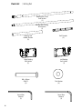
|Parts List Batting Rail
5mm Allen
Wrench
(1)
4mm Allen
Wrench
(1)
M8 x 60mm
SBHCS
(4)
Flat Washer
(4)
Rail Coupler
(3)
Batting Rail Fixed
End Section
(1)
Batting Rail Floating
End Section
(1)
Batting Rail
Middle Section
(2)
Left Batting
Rail Holder
(1)
Right Batting
Rail Holder
(1)

4mm Allen Wrench
Rail Coupler
Bolt
2-1 Slide the Batting Rail Fixed End Section onto
Rail Coupler, tight against the appropriate Rail
Section, and secure rail by backing screws out.
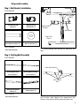
Step 1 - Rail Bracket Installation
1-1 Install Batting Rail Bracket on right and left
legs.
M8 x 60mm SBHCS (4)
Left Batting Rail
Holder (1)
Parts Needed:
Right Batting
Rail Holder (1)
M8 Flat Washer (4)
Tools Needed:
5mm Allen Wrench
Parts Needed:
Step 2 - Batting Rail Assembly
Rail Coupler (3)
Batting Rail Middle
Section (2)
Batting Rail Floating
End Section (1)
Batting Rail Fixed
End Section (1)
Tools Needed:
4mm Allen Wrench
1
Setup and Assembly
Right Side
Shown
Batting Rail
Bracket
M8 x 60mm
SBHCS
M8 Washer

2-2 Assemble the Batting Rail.
Note: Align holes and tighten on one side then repeat for other side.
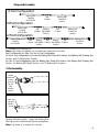
See Crib Assembly for Step 2 for the 4 Foot Conguration.
For the 8 foot conguration only use the Batting Rail Fixed End Section, the Batting Rail Floating End
Section, and (1) Batting Rail Coupler.
For the 10 foot conguration use the Batting Rail Fixed End Section, the Batting Rail Floating End
Section, the Batting Rail Middle Section, and (2) Batting Rail Couplers.
Crib Assembly
Loosen
screw and
remove
end cap
Do not
fully
remove
screw
Insert end
cap and
tighten
screw
2-2a Remove Floating End Rail Cap from the
Floating End Rail Section. Insert the Floating End
Rail Cap into the Fixed End Rail Section and tighten.
Note: Tap screw in to release the rail cap.
2
Setup and Assembly
Batting Rail
Fixed End
Section
Rail
Coupler
Rail
Coupler
Rail
Coupler
Batting Rail
Floating
End Section
Batting
Rail Middle
Section
Batting
Rail Middle
Section
8 Foot Conguration
10 Foot Conguration
12 Foot Conguration
Rail
Coupler
Batting Rail
Floating
End Section
Batting
Rail Middle
Section
Batting Rail
Fixed End
Section
Rail
Coupler
Batting Rail
Fixed End
Section
Rail
Coupler
Batting Rail
Floating
End Section

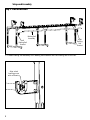
3-1 Install Batting Rail Assembly onto Batting Rail Brackets with the oating end to the left.
Step 3 - Rail Installation
3
Setup and Assembly
Batting Rail
Assembly
Left
Batting Rail
Bracket
Right
Batting
Rail
Bracket
Align wheel
bearing groove
with rail bearing

The Grace Company
2225 South 3200 West
Salt Lake City, UT 84119
Phone: 1-800-264-0644
Fax: 801-908-8888
www.graceframe.com
-
 1
1
-
 2
2
-
 3
3
-
 4
4
-
 5
5
-
 6
6


GraceWood The Continuum Frame Operating instructions
- Type
- Operating instructions
- This manual is also suitable for
Ask a question and I''ll find the answer in the document
Finding information in a document is now easier with AI
Related papers

Other documents
-
 Grace Company The Continuum Frame Operating instructions
-
 Grace Company Continuum Frame Operating instructions
-
 Grace Company Q-Zone Queen Operating instructions
-
 Grace Company The Gracie King and Gracie Queen Operating instructions
-
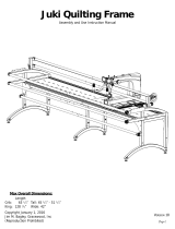 Grace Company The Juki Frame Operating instructions
-
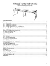 Grace Company The Q'nique Frame Operating instructions
-
Grace Company Continuum II Frame Assembly Instructions
-
-
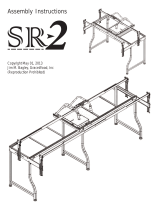 Grace Company SR-2 Frame Operating instructions
-
 Grace Company SR-2 Frame Operating instructions


