3M DBI-SALA® Delta™ Arc Flash Harness, Dorsal/Rescue Web Loops 1110780, Medium, 1 EA Operating instructions

Type
Operating instructions
© Copyright 2009, DB Industries, Inc.
USER INSTRUCTION MANUAL
FULL BODY HARNESS
This manual is intended to meet the Manufacturer’s Instructions
as required by ANSIZ359 and CSA 259.10 and should be used as
part of an employee training program as required by OSHA
Instructions for the
following series products:
Full Body Harnesses
(See back pages for specic
model numbers.)
Form: 5908231
Rev: M
3
Figure 1 - Delta Vest™ Full Body Harness
Shoulder Strap
(inside vest)
Chest Strap
Leg Strap
Attachment
Element for
Fall Arrest
(D-ring or
Web Loop)
Labels and
RFID Tag
(inside vest)
4
Figure 2 - Vest Style Full Body Harness
Leg Strap
D-ring Pad
Chest Strap
Attachment
Element for
Fall Arrest
(D-ring or
Web Loop)
Shoulder Strap
Labels and
RFID Tag
5
Figure 3 - Cross-over Style Full Body Harness
Labels and
RFID Tag
Leg Strap
Attachment
Element for
Fall Arrest
(D-ring or
Web Loop)
D-ring Pad
Front Attachment Element
(D-ring or Web Loop)
Shoulder Strap
6
Figure 4 - Step-in Style Full Body Harness
Labels and
RFID Tag
Attachment
Element for
Fall Arrest
(D-ring or
Web Loop)
Shoulder Strap
Front D-ring
D-ring Pad
Leg Strap
7
WARNING: This product is part of a personal fall arrest, restraint,
work positioning, personnel riding, climbing, or rescue system. The
user must follow the manufacturer’s instructions for each component
of the system. These instructions must be provided to the user of this
equipment. The user must read and understand these instructions
before using this equipment. Manufacturer’s instructions must be
followed for proper use and maintenance of this equipment. Alterations
or misuse of this product or failure to follow instructions may result in
serious injury or death.
IMPORTANT: If you have questions on the use, care, or suitability of
this equipment for your application, contact DBI‑SALA.
IMPORTANT: Before using this equipment, record the product
identication information from the ID label in the inspection and
maintenance log in section 9.0 of this manual.
DESCRIPTIONS
Delta Vest™ Full Body Harness: See Figure 1.
Vest Style Full Body Harness: See Figure 2.
Cross-Over Style Full Body Harness: See Figure 3.
Step-In Style Full Body Harness: See Figure 4.
OPTIONS:
DBI-SALA Full Body Harnesses are available with options and
accessories. Following is a partial list of commonly used options
and accessories (some options may not be available on all
harnesses):
Shoulder D-rings
Side D-rings
Hip pad with side D-rings
Quick Connect buckles
Tongue buckle body belt
Loops on harness for body belt
Kevlar
®
webbing
High visibility webbing
Non-sparking/Non conductive PVC coated hardware
Shoulder pads
Tool belt support straps
Seat sling
Lanyard attached directly to D-ring or attachment element
Snap fastener on shoulder strap for retaining lanyard
Delta Vest™
Tool holders
8
1.0 APPLICATIONS
1.1 PURPOSE: DBI-SALA full body harnesses are to be used as
components in personal fall arrest, restraint, work positioning, or
rescue systems. See Figures 1, 2, 3, and 4 for harness styles.
Harnesses included in this manual are full body harnesses and
meet ANSI Z359.1, OSHA, and CSA Z259.10 requirements. See
Figure 5 for application illustrations.
Full body harnesses with Kevlar web should be used when
working with tools, materials, or environments of high
temperature (foundries, chemical manufacturing, steel
fabrication, emergency rescue services, re services, welders,
oil industry, nuclear industry, explosives).
Harnesses with PVC coated hardware should be used when
working in explosive or electrically conductive environments, or
where surfaces must be protected from the hardware.
Harnesses with high visibility webbing should be used when
increased visibility of the user is required.
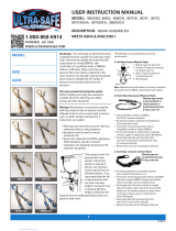
A. PERSONAL FALL ARREST: The full body harness
is used as a component of a personal fall arrest
system. Personal fall arrest systems typically
include a full body harness and a connecting
subsystem (energy absorbing lanyard). Maximum
arresting force must not exceed 1,800 lbs (8
kN).For fall protection applications connect the
fall arrest subsystem (example: lanyard, SRL,
energy absorber, etc.) to the D-ring or attachment
element on your back, between your shoulder
blades.
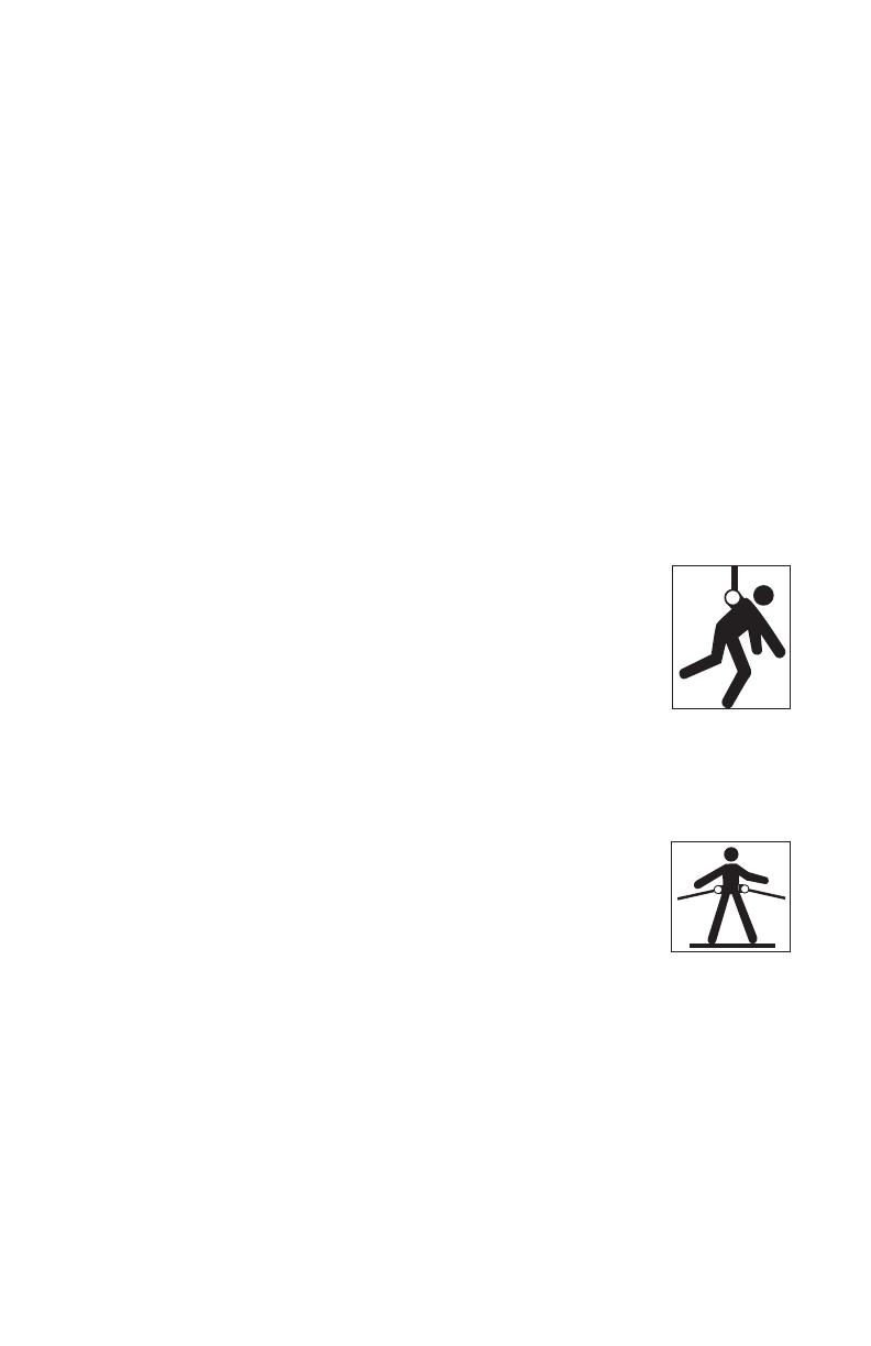
B. WORK POSITIONING: The full body harness
is used as a component of a work positioning
system to support the user at a work position.
Work positioning systems typically include a full
body harness, positioning lanyard, and a back-up
personal fall arrest system. For work positioning
applications, connect the work positioning
subsystem (example: lanyard, Y-lanyard, etc.)
to the lower (hip level) side or belt mounted
work positioning attachment anchorage elements
(D-rings). Never use these connection points for
fall arrest.
9
C. LADDER CLIMBING: The full body harness
is used as a component of a climbing system
to prevent the user from falling when climbing
a ladder or other climbing structure. Climbing
systems typically include a full body harness,
vertical cable or rail attached to the structure, and
climbing sleeve.For ladder climbing applications,
harnesses equipped with a frontal D-ring in the
sternal location may be used for fall arrest on
xed ladder climbing systems. These are dened
in Z259.2.1 in Canada and ANSI A14.3 in the
United States.
D. RESCUE: The full body harness is used as a
component of a rescue system. Rescue systems
are configured depending on the type of rescue.
For limited access (conned space) applications,
harnesses equipped with D-rings on the shoulders
may be used for entry and egress into conned
spaces where worker prole is an issue.
Figure 5 - Applications
Anchorage
Anchorage
Anchorage Connector
Restraint Lanyard
Anchorage Connector
Connecting Subsystem
(Self Retracting Lifeline
Shown)
Full Body Harness
Full Body Harness
Fall Arrest
Restraint
Work Positioning
Anchorage
Anchorage
Connecto
r
Back-up Fall
Arrest System
Full Body
Harness
Restraint Lanyard
Anchorage
Anchorage
Connector
Ladder
Cable Sleeve
Cable
Cross-over
Full Body
Harness
Ladder Climbing
10
E. CONTROLLED DESCENT: For controlled descent
applications, harnesses equipped with a single
sternal level D-ring, one or two frontal mounted
D-rings, or a pair of connectors originating below
the waist (such as a seat sling) may be used for
connection to a descender or evacuation system
(reference in Z259.10 in Canada).
F. RESTRAINT: The full body harness is used as a component
of a restraint system to prevent the user from reaching a fall
hazard. Restraint systems typically include a full body harness
and a lanyard or restraint line.
1.2 LIMITATIONS: Consider the following application limitations
before using this equipment:
A. CAPACITY: These full body harnesses are designed for use
by persons with a combined weight (clothing, tools, etc.) of no
more than 420 lbs. Make sure all of the components in your
system are rated to a capacity appropriate to your application
B. FREE FALL: Personal fall arrest systems used with this
equipment must be rigged to limit the free fall to 6 feet (1.8
M) (ANSI Z359.1). Restraint systems must be rigged so that
no vertical free fall is possible. Work positioning systems must
be rigged so that free fall is limited to 2 feet (.6 m) or less.
Personnel riding systems must be rigged so that no vertical
free fall is possible. Climbing systems must be rigged so that
free fall is limited to 18 in. (.46 cm) or less. Rescue systems
must be rigged so that no vertical free fall is possible. See
subsystem manufacturer’s instructions for more information.
C. FALL CLEARANCE: See Figure 6. There must be sufcient
clearance below the user to arrest a fall before the user strikes
the ground or other obstruction. The clearance required is
dependent on the following factors:
Elevation of anchorage
Connecting subsystem length
Deceleration distance
Free fall distance
Worker height
Movement of harness attachment element
See subsystem manufacturer’s instructions for more information.
11
Figure 6 - Fall Clearance
Connecting Subsystem
(Energy Absorbing Lanyard
shown)
Working Level
Free Fall
6 ft. max
(ANSI Z359.1)
Deceleration
Distance
Total Fall Distance
(Free Fall +
Deceleration)
Lower Level or Obstruction
NOTE: When calculating
fall clearance, an
additional 6 in. (15.3
cm) should be included
to allow for expected
harness stretch.
Figure 7 - Swing Fall
Swing
Fall
Hazard
D. SWING FALLS: See Figure 7. Swing falls occur when the
anchorage point is not directly above the point where a fall
occurs. The force of striking an object in a swing fall may
cause serious injury or death. Minimize swing falls by working
as close to the anchorage point as possible. Do not permit
a swing fall if injury could occur. Swing falls will signicantly
increase the clearance required when a self-
retracting lifeline or
other variable length connecting subsystem is used.
E. EXTENDED SUSPENSION: A full body harness is not
intended for use in extended suspension applications. If the
user is going to be suspended for an extended length of time
it is recommended that some form of seat support be used.
DBI-SALA recommends a seat board, suspension workseat,
seat sling, or a boatswain chair. Contact DBI-SALA for more
information on these items.
F. ENVIRONMENTAL HAZARDS: Use of this equipment in areas
with environmental hazards may require additional precautions
to prevent injury to the user or damage to the equipment.
Hazards may include, but are not limited to; heat, chemicals,
corrosive environments, high voltage power lines, gases,
moving machinery, and sharp edges.
G. HARNESSES FOR HIGH TEMPERATURE ENVIRONMENTS:
Harnesses with Kevlar webbing are designed for use in high
temperature environments, with limitations: Kevlar webbing
begins to char at 800° to 900° Fahrenheit. Kevlar webbing
can withstand limited contact exposure to temperatures up to
1,000° F. Polyester webbing loses strength at 300° to 400° F.
PVC coating on hardware has a melting point of approximately
350° F.
12
IMPORTANT: When working with tools, materials, or in high
temperature environments, ensure that associated fall protection
equipment can withstand high temperatures, or provide protection for
those items.
IMPORTANT: Although PVC coated, cadmium, or zinc plated hardware
exhibit excellent corrosion resistance in chemical, acidic, alkaline, and
atmospheric conditions, frequent inspections may be required. Consult
with DBI‑SALA if you question the use of this equipment in hazardous
environments.
H. TRAINING: This equipment must be installed and used by
persons trained in its correct application and use. See section
4.0.
1.3 APPLICABLE STANDARDS: Refer to national standards, including
ANSI Z359 (.0, .1, .2, .3, and .4) family of standards on fall
protection, ANSI A10.32, CSA Z259.10, and applicable local, state
and federal (OSHA) requirements governing occupational safety for
more information about work positioning systems.
IMPORTANT: Harnesses with Kevlar webbing do not meet ANSI
Z359.1. Kevlar does not have equivalent abrasion resistance of
polyamides. Kevlar harnesses meet all other requirements of this
standard.
2.0 SYSTEM REQUIREMENTS
2.1 COMPATIBILITY OF COMPONENTS: DBI-SALA equipment
is designed for use with DBI-SALA approved components and
subsystems only. Substitutions or replacements made with non-
approved components or subsystems may jeopardize compatibility
of equipment and may effect the safety and reliability of the
complete system.
2.2 COMPATIBILITY OF CONNECTORS: Connectors are considered
to be compatible with connecting elements when they have been
designed to work together in such a way that their sizes and
shapes do not cause their gate mechanisms to inadvertently open
regardless of how they become oriented. Contact DBI-SALA if you
have any questions about compatibility.
Connectors (hooks, carabiners, and D-rings) must be capable
of supporting at least 5,000 lbs. (22.2 kN). Connectors must be
compatible with the anchorage or other system components.
Do not use equipment that is not compatible. Non-compatible
connectors may unintentionally disengage. See Figure 8.
Connectors must be compatible in size, shape, and strength. Self-
locking snap hooks and carabiners are required by ANSI Z359.1
and OSHA.
13
2.3 MAKING CONNECTIONS: Use only self-locking snap hooks and
carabiners with this equipment. Use only connectors that are
suitable to each application. Ensure all connections are compatible
in size, shape and strength. Do not use equipment that is not
compatible. Ensure all connectors are fully closed and locked.
DBI-SALA connectors (snap hooks and carabiners) are designed to
be used only as specied in each product’s user’s instructions. See
Figure 9 for inappropriate connections. DBI-SALA snap hooks and
carabiners should not be connected:
A. To a D-ring to which another connector is attached.
B. In a manner that would result in a load on the gate.
Figure 8 - Unintentional Disengagement (Rollout)
If the connecting element to which a snap hook (shown) or carabiner
attaches is undersized or irregular in shape, a situation could occur
where the connecting element applies a force to the gate of the snap
hook or carabiner. This force may cause the gate (of either a self-
locking or a non-locking snap hook) to open, allowing the snap hook or
carabiner to disengage from the connecting point.
Small ring or
other non-
compatibly
shaped element
1.FORCE IS APPLIED TO
THE SNAP HOOK.
2. THE GATE PRESSES
AGAINST THE
CONNECTING RING
3. THE GATE OPENS
ALLOWING THE
SNAP HOOK TO
SLIP OFF
NOTE: Large throat snap hooks should not be connected to standard
size D‑rings or similar objects which will result in a load on the gate
if the hook or D‑ring twists or rotates, unless the snap hook complies
with ANSI Z359.1‑2007 and is equipped with a 3,600 lb gate. Check
the marking on your snap hook to verify that it is appropriate for your
application.
C. In a false engagement, where features that protrude from the
snap hook or carabiner catch on the anchor, and without visual
conrmation seems to be fully engaged to the anchor point.
14
Figure 9 - Inappropriate Connections
D. To each other.
E. Directly to webbing or rope lanyard or tie-back (unless the
manufacturer’s instructions for both the lanyard and connector
specically allows such a connection).
F. To any object which is shaped or dimensioned such that the
snap hook or carabiner will not close and lock, or that roll-out
could occur.
2.4 CONNECTING SUBSYSTEMS: Connecting subsystems (self-
retracting lifeline, lanyard, rope grab and lifeline, cable sleeve)
must be suitable for your application. See section 1.1. See
subsystem manufacturer’s instructions for more information. Some
harness models have web loop connection points. Do not use
snap hooks to connect to web loops. Use a self-locking carabiner
to connect to a web loop. Ensure the carabiner cannot cross-gate
load (load against the gate rather than along the backbone of the
carabiner). Some lanyards are designed to choke onto a web loop
to provide a compatible connection. See Figure 10. Lanyards may
be sewn directly to the web loop forming a permanent connection.
Do not make multiple connections onto one web loop, unless
choking two lanyards onto a properly sized web loop.
2.5 ANCHORAGE STRENGTH: The anchorage strength required
is dependent on the application type. The following are the
requirements of ANSI 359.1 for these application types:
A. FALL ARREST: Anchorages selected for fall arrest systems
shall have a strength capable of sustaining static loads applied
in the directions permitted by the system of at least:
1. 5,000 lbs. (22.2 kN) for non-certified anchorages, or
2. Two times the maximum arresting force for certified
anchorages. When more than one fall arrest system is
15
attached to an
anchorage, the
strengths set
forth in (1) and
(2) above shall
be multiplied
by the number
of systems
attached to the
anchorage.
B. RESTRAINT:
Anchorages
selected for
restraint and
travel restraint
systems shall
have a strength
capable of
sustaining
static loads
applied in the
directions permitted by the system of at least:
1. 1,000 lbs. (4.5 kN) for non-certied anchorages, or
2. Two times the foreseeable force for certied anchorages.
When more than one restraint and travel restraint system
is attached to an anchorage, the strengths set forth in (1)
and (2) above shall be multiplied by the number of systems
attached to the anchorage.
C. WORKING POSITIONING: Anchorages selected for work
positioning systems shall have a strength capable of sustaining
static loads applied in the directions permitted by the system
of at least:
1. 3,000 lbs. (13.3 kN) for non-certied anchorages, or
2. Two times the foreseeable force for certied anchorages. When
more than one work positioning system is attached to an anchorage,
the strengths set forth in (1) and (2) above shall be multiplied by the
number of systems attached to the anchorage.
D. RESCUE: Anchorages selected for rescue systems shall have a
strength capable of sustaining static loads applied in the directions
permitted by the system of at least:
1 . 3,000 lbs. (13.3 kN) for non-certified anchorages, or
2. Five times the foreseeable force for certified anchorages. When
more than one rescue system is attached to an anchorage, the
strengths set forth in (1) and (2) above shall be multiplied by the
number of systems attached to the anchorage.
E. CLIMBING: The structure to which a climbing system is attached
must sustain the loads required by that particular system. See
instructions for climbing system for requirements.
Figure 10 - Web Loop Connection
Insert lanyard web loop through
web loop or D-ring on harness
Harness Web Loop
or D-ring
Web Loop on
Energy Absorbing Lanyard
Insert appropriate end of lanyard
through the lanyard web loop
Pull the lanyard through the
connecting web loop to secure
16
3.0 DONNING AND USE
WARNING: Do not alter or intentionally misuse this equipment. Consult
DBI‑SALA when using this equipment in combination with components or
subsystems other than those described in this manual. Some subsystem
and component combinations may interfere with the operation of this
equipment. Use caution when using this equipment around moving
machinery, electrical and chemical hazards, and sharp edges.
WARNING: Consult your doctor if there is reason to doubt your
tness to safely absorb the shock from a fall arrest. Age and tness
seriously affect a worker’s ability to withstand falls. Pregnant women
or minors must not use any DBI‑SALA full body harness.
3.1 BEFORE EACH USE of this equipment inspect it according to
section 5.0 of this manual.
3.2 PLAN your system before use. Consider all factors that will affect
your safety during use of this equipment. The following list gives
important points to consider when planning your system:
A. ANCHORAGE: Select an anchorage that meets the
requirements specied in sections 1.2 and 2.5.
B. SHARP EDGES: Avoid working where system components
may be in contact with, or abrade against, unprotected sharp
edges.
C. AFTER A FALL: Components which have been subjected to
the forces of arresting a fall must be removed from service and
destroyed.
D. RESCUE: The employer must have a rescue plan when using
this equipment. The employer must have the ability to perform
a rescue quickly and safely.
17
3.3 DONNING AND FITTING THE HARNESS:
A. DELTA VEST™ HARNESS: See Figure 11 for front and back
views of the Delta Vest™ harness. Don the Delta Vest™ full
body harness by following these steps (see Figures 12 and 13).
Figure 11 - Front and Back View of Delta Vest™ Harness
Step 1. Lift harness by the back D-ring and untangle straps.
Allow leg straps to hang free.
Step 2. Don the Vest Harness as you would a jacket. Do not zip
the vest at this time.
Step 3. Connect chest strap by passing male buckle through
female buckle. Pass excess webbing through loop
keepers. See Figure 13.
Step 4. Reach between legs and grasp blue leg strap on your
left side. Bring strap up between legs and connect to
buckle attached to yellow strap (orange on high visibility
models, black on ame resistant models) as shown in
Figures 12 and 13. Connect right leg strap.
Step 5. Reach inside the vest and adjust shoulder straps to
a snug t. Left and right shoulder straps should be
adjusted to the same length. Readjust leg straps, chest
strap, and shoulder straps as necessary to a snug t.
Step 6. Zip the vest.
18
Figure 12 - Donning the Delta Vest™ Harness
Delta Vest™ Harness
Step 1 Step 2 Step 3
Step 4 Step 5 Step 6
19
B. VEST STYLE
HARNESS: If your
harness incorporates
loops for a removable
waist belt, the belt
should be installed
through the four loops
in the harness as shown
in Figure 14. The hip
pad, if used, is secured
to the belt by passing
the belt through the hip
pad loops. Don the vest
style full body harness
by following these steps
(see Figures 15 and
16):
Step 1. Locate back D-ring held in position by the D-ring pad;
lift up harness and hold by this D-ring. Ensure the straps
are not twisted.
Step 2. Grasp the shoulder straps and slip harness onto one
arm. D-ring will be located on your back side. Ensure
Figure 13 - Delta Vest™ Harness Buckle Connections
Chest Strap: Pass male buckle
through female buckle and pull free
end of webbing to tighten.
Tongue Buckle: Pass webbing
through buckle and insert tongue
through grommet.
Parachute Buckle: Pass webbing
under buckle and over roller and
down between roller and frame.
Pull web end to tighten. Three
inches of web must extend past
buckle.
Pass Buckle: Pass male buckle
through female buckle and pull free
end of webbing to tighten.
Figure 14 - Removable Waist Belt
& Hip Pad
20
Figure 15 - Donning Vest Style Harness
Step 1
Step 2
Step 3
Step 4 Step 5
  • Page 1 1
  • Page 2 2
  • Page 3 3
  • Page 4 4
  • Page 5 5
  • Page 6 6
  • Page 7 7
  • Page 8 8
  • Page 9 9
  • Page 10 10
  • Page 11 11
  • Page 12 12
  • Page 13 13
  • Page 14 14
  • Page 15 15
  • Page 16 16
  • Page 17 17
  • Page 18 18
  • Page 19 19
  • Page 20 20
  • Page 21 21
  • Page 22 22
  • Page 23 23
  • Page 24 24
  • Page 25 25
  • Page 26 26
  • Page 27 27
  • Page 28 28
  • Page 29 29
  • Page 30 30
  • Page 31 31
  • Page 32 32
  • Page 33 33
  • Page 34 34
  • Page 35 35
  • Page 36 36
  • Page 37 37
  • Page 38 38
  • Page 39 39
  • Page 40 40
  • Page 41 41
  • Page 42 42
  • Page 43 43
  • Page 44 44

3M DBI-SALA® Delta™ Arc Flash Harness, Dorsal/Rescue Web Loops 1110780, Medium, 1 EA Operating instructions

Type
Operating instructions

Ask a question and I''ll find the answer in the document

Finding information in a document is now easier with AI