Page is loading ...

USER INSTRUCTION MANUAL
WEB AND ROPE LANYARDS, D-RING EXTENSION
This manual is intended to meet the Manufacturer’s Instructions as
recommended by OSHA, and should be used as part of an employee
training program.
DESCRIPTION
Nylon Rope Lanyards: Polyester Web Lanyards/D-Ring Extension:
Adjustable 1/2 inch (1.3 cm) rope, self-locking snap hook each end. Adjustable 1 inch (2.5 cm) web, self-locking snap hook each end.
Adjustable 5/8 inch (1.6 cm) rope, self-locking snap hook each end. 1 inch (2.5 cm) web, self-locking snap hook each end.
1/2 inch (1.3 cm) rope, self-locking snap each end. 1 inch (2.5 cm) web, self-locking hook, D-ring (D-ring extension).
1/2 inch (1.3 cm) rope, self-locking snap hook, carabiner other end. 1 inch (2.5 cm) web, self-locking snap hook, carabiner other end.
5/8 inch (1.6 cm) rope, self-locking snap hook each end. 1 inch (2.5 cm) web, self-locking snap hook, closed loop choker.
1inch(2.5cm)web,SaokMaxhook,D-ring
Polyester Rope Lanyards: Kevlar Web Lanyards:
Adjustable 1/2 inch (1.3 cm) rope, self-locking snap hook each end. 1-3/4 inch (4.5 cm) Kevlar web, self-locking snap hook each end.
Adjustable 5/8 inch (1.6 cm) rope, self-locking snap hook each end. 1-3/4 inch (4.5 cm) Kevlar web, self-locking snap hook, 1-3/16 inch
1/2 inch (1.3 cm) rope, self-locking snap hook each end. (3 cm) throat carabiner.
1/2 inch (1.3 cm) rope, self-locking snap hook, carabiner other end.
5/8 inch (1.6 cm) rope, self-locking snap hook each end.
Nylon Web Lanyards:
Polyester Y-Lanyards: Adjustable 1 inch (2.5 cm) web, self-locking snap hook each end.
1-3/4 inch (4.5 cm) polyester web, self-locking snap hook each end, 1 inch (2.5 cm) web, self-locking snap hook each end.
spreader bar, center D-ring.
1-3/4 inch (4.5 cm) polyester web, self-locking snap hook each Wristlets:
end, center D-ring. 1 inch (2.5 cm) web, center O-ring, wrist loop each end.
1 inch (2.5 cm) web, Y style, center D-ring, wrist loop each end.
Nylon Rope Y-Lanyard: 1 inch (2.5 cm) web, Detachable style, O-ring, 1 wrist loop.
1/2inch(1.3cm)rope,SaokMaxhookeachend,centerself-locking
snaphook
© 3M 2019
Instructions for the following series products:
Web Lanyards, Rope Lanyards, D-Ring Extensions
(Seebackpagesforspecicmodelnumbers.)
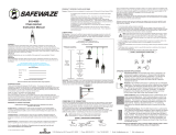
Figure 1 - Web and Rope Lanyards
Stitching
Stitching
Stitching
Label
Label
Label
Label
Label
Label
Lanyard
Lanyard
Lanyard
Lanyard
Wristlets
Nylon or Polyester Web Lanyard
Kevlar Web Lanyard
Nylon or Polyester Rope Lanyard
D-ring Extension
Lanyard
Y-Lanyard
D-ring
D-ring
Spreader Bar
O-ring
Self-Locking
Snap Hook
Self-Locking
Snap Hook
Self-Locking
Snap Hook
Self-Locking
Snap Hook
Self-Locking
Snap Hook
Wrist Loop
Wrist Loop
Form: 5902126 Rev: L

2
WARNING: This product is part of a personal restraint, work positioning, suspension, or rescue system. These
instructions must be provided to the user and rescuer (see section 8 Terminology). The user must read and
understand these instructions or have them explained to them before using this equipment. The user must read
and follow the manufacturer’s instructions for each component or part of the complete system. Manufacturer’s
instructions must be followed for proper use and maintenance of this product. Alterations or misuse of this
product or failure to follow instructions may result in serious injury or death.
IMPORTANT: If you have questions on the use, care, application, or suitability for use of this equipment,
contact DBI‑SALA.
IMPORTANT: Before using this equipment record the product identication information (found on the I.D. label)
in the Inspection and Maintenance Log at the back of this manual.
1.0 APPLICATION
1.1 PURPOSE: DBI-SALA
lanyards are to be used
as part of a personal
restraint, work positioning,
suspension, or rescue
system. The D-ring
extension assembly may
also be used as part of a
personal fall arrest system
only if it is attached to
a self retracting lifeline
or an energy absorbing
lanyard. Applications
include: inspection work,
construction, demolition,
maintenance, oil production,
andconnedspacerescue.
See Figure 2.
A. RESTRAINT: The
lanyard is used to
prevent the user from
reaching a hazard, such
as leading edge work.
No vertical free fall is
possible.
B. WORK POSITIONING: The lanyard is used to position or support (with a harness or body belt) the
user at the work position, such as window washing or steel workers. The maximum free fall is 2 feet
(.6 m).
C. SUSPENSION: The lanyard (generally a Y-type) is used with a chair or other support system to suspend
or transport the user vertically, such as in a boatswain’s chair. No vertical free fall is possible.
D. RESCUE: The lanyard (generally a Y-type or wristlet) is used to retrieve a victim in a rescue, such as
confined space rescue and retrieval. No vertical free fall is possible.
E. FALL ARREST: The D-ring extension is used in-line with a personal fall arrest system to assist in
attachment to the system.
1.2 LIMITATIONS: The following application limitations must be recognized and considered before using this
product:
A. CAPACITY: This equipment is for use by persons with a combined weight (person, clothing, tools, etc.)
of no more than 310 lbs. (140.6 kg.)
B. FREE FALL: Lanyards used for work positioning applications must be rigged to minimize any potential
vertical free fall. In no case should the potential free fall be greater than 2 feet (.6 m). For situations
where the free fall may exceed 2 feet (.6 m), a backup fall arrest system should be used. The Y-lanyards
and wristlets may only be used where there is no possible vertical free fall.
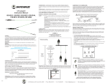
Figure 2 - Applications
NOTE: The fall arrest application is
for the D-ring extension only.
Work Positioning Restraint Rescue
Fall Arrest
Suspension
Rescue
Back-up
Fall
Arrest
Option
Lanyard
Lanyard
Rescue Line
Wristlets
Locking
Snap Hook
or Carabiner
Locking Snap Hook or
Carabiner
Y Lanyard
Self
Retracting
Lifeline
D-ring
Extension
D-ring
Extension
Snap
Dorsal
D-ring
Suspension Line
Back-up
Fall
Arrest
Rescue Line
Locking
Snap Hook
or Carabiner
Y Lanyard

3
If the D-ring extension assemblies are used in conjunction with a self retracting lifeline or an energy
absorbing lanyard in a fall arrest application, the length of the D-ring extension assembly must be taken
into account when calculating the free fall distance and the fall clearance requirements.
C. FALL CLEARANCE: Ensure that enough clearance exists in your fall path to prevent striking an object.
The amount of clearance needed is dependent on the type and length of the lanyard used and anchorage
location. See section 1.2 B.
D. BACKUP FALL ARREST SYSTEM: Some applications of this equipment may require the use of a backup
fall arrest system; such as when using a Y-lanyard to suspend a person in a boatswain’s chair.
E. PHYSICAL AND ENVIRONMENTAL HAZARDS: Use of this equipment in areas with physical or
environmental hazards may require additional precautions to reduce the possibility of injury to the user or
damage to the equipment. Hazards may include, but are not limited to: heat, severe cold, chemicals, corrosive
environments, high voltage power lines, gases, moving machinery, and sharp edges. Contact DBI-SALA if you have
any questions about using this equipment where physical or environmental hazards exists.
F. TRAINING: This equipment must be used by persons who have been properly trained in its correct
application and use.
1.3 Refer to national Standards including ANSI Z359 (.0, .1, .2, .3, and .4) family of standards on fall
protection, ANSI A10.32, and applicable local, state and federal (OSHA) requirements governing
occupational safety for more information about work positioning systems.
2.0 SYSTEM REQUIREMENTS
2.1 COMPATIBILITY OF COMPONENTS: DBI-SALA equipment is designed for use with DBI-SALA approved
components and subsystems only. Substitutions or replacements made with non-approved components
or subsystems may jeopardize compatibility of equipment and may effect the safety and reliability of the
complete system.
2.2 COMPATIBILITY OF CONNECTORS: Connectors are considered to be compatible with connecting
elements when they have been designed to work together in such a way that their sizes and shapes do
not cause their gate mechanisms to inadvertently open regardless of how they become oriented. Contact
DBI-SALA if you have any questions about compatibility.
Connectors (hooks, carabiners, and D-rings) must be capable of supporting at least 5,000 lbs. (22.2kN).
Per ANSI Z359.1, connector gates must be able to withstand a load of 3,600 lbs (16 kN): the face of the
gate must withstand 3,600 lbs (16 kN); the side of the gate must withstand 3,600 lbs (16 kN), and the
minor axis for a snap hook or carabiner must withstand 3,600 lbs (16 kN), except those with captive eyes.
Connectors must be compatible with the anchorage or other system components. Do not use equipment
that is not compatible. Non-compatible connectors may unintentionally disengage. See Figure 3. Connectors
must be compatible in size, shape, and strength. Self locking snap hooks and carabiners are required by
ANSI Z359.1 and OSHA.
2.3 MAKING CONNECTIONS: Use only self-locking snap hooks and carabiners with this equipment. Use only
connectors that are suitable to each application. Ensure all connections are compatible in size, shape and
strength. Do not use equipment that is not compatible. Ensure all connectors are fully closed and locked.
DBI-SALAconnectors(snaphooksandcarabiners)aredesignedtobeusedonlyasspeciedineach
product’s user instructions. See Figure 3 for inappropriate connections. DBI-SALA snap hooks and carabiners
should not be connected:
A. To a D-ring to which another connector is attached.
B. In a manner that would result in a load on the gate.
NOTE: Large throat‑opening snap hooks should not be connected to standard size D‑rings or similar objects
which will result in a load on the gate if the hook or D‑ring twists or rotates. Large throat snap hooks are
designed for use on xed structural elements such as rebar or cross members that are not shaped in a way that
can capture the gate of the hook.
C. In a false engagement, where features that protrude from the snap hook or carabiner catch on the
anchor, and without visual confirmation seems to be fully engaged to the anchor point.
D. To each other.
E. Directly to webbing or rope lanyard or tie-back (unless the manufacturer’s instructions for both the
lanyard and connector specifically allow such a connection).

4
F. To any object which is shaped or dimensioned such that the snap hook or carabiner will not close and
lock, or that roll-out could occur.
G. In a manner that does not allow the connector to align properly while under load.
Figure 3 Unintentional Disengagement and Inappropriate Connections
If the connecting element to which a snap hook (shown) or carabiner
attaches is undersized or irregular in shape, a situation could occur
where the connecting element applies a force to the gate of the snap
hook or carabiner. This force may cause the gate (of either a self-
locking or a non-locking snap hook) to open, allowing the snap hook or
carabiner to disengage from the connecting point.
Small ring or other
non-compatibly
shaped element
Force is applied to the
Snap Hook.
The Gate presses against
the Connecting Ring.
The Gate opens allowing
the Snap Hook to slip off.
2.4 ANCHORAGE STRENGTH: The anchorage strength required is dependent on the application type. The
following are the requirements of ANSI 359.1 for these application types:
A. FALL ARREST: Anchorages selected for fall arrest systems shall have a strength capable of sustaining
static loads applied in the directions permitted by the system of at least:
1. 5,000 lbs. (22.2 kN) for non-certified anchorages, or
2. Two times the maximum arresting force for certified anchorages. When more than one fall arrest
system is attached to an anchorage, the strengths set forth in (1) and (2) above shall be multiplied by
the number of systems attached to the anchorage.
B. WORKING POSITIONING: Anchorages selected for work positioning systems shall have a strength
capable of sustaining static loads applied in the directions permitted by the system of at least:
1.3,000lbs.(13.3kN)fornon-certiedanchorages,or
2.Twotimestheforeseeableforceforcertiedanchorages.Whenmorethanoneworkpositioning
system is attached to an anchorage, the strengths set forth in (1) and (2) above shall be multiplied by
the number of systems attached to the anchorage.
C. RESTRAINT: Anchorages selected for restraint and travel restraint systems shall have a strength
capable of sustaining static loads applied in the directions permitted by the system of at least:
1.1,000lbs.(4.5kN)fornon-certiedanchorages,or
2.Twotimestheforeseeableforceforcertiedanchorages.Whenmorethanonerestraintandtravel
restraint system is attached to an anchorage, the strengths set forth in (1) and (2) above shall be
multiplied by the number of systems attached to the anchorage.
D. RESCUE: Anchorages selected for rescue systems shall have a strength capable of sustaining static
loads applied in the directions permitted by the system of at least:
1. 3,000 lbs. (13.3 kN) for non-certified anchorages, or
2. Five times the foreseeable force for certified anchorages. When more than one rescue system is
attached to an anchorage, the strengths set forth in (1) and (2) above shall be multiplied by the number
of systems attached to the anchorage.
WARNING: Anchorages used for restraint, rescue, or suspension may only be used where there is no possible
vertical free fall. These anchorages do not have sufcient strength for work positioning or fall arrest. Do not
connect work positioning or fall arrest systems to these anchorages. Anchorages intended for work positioning
may not be suitable for use with fall arrest systems (fall greater than 2 feet (.6 m)) and should not be used for
fall arrest unless specically designed to do so.

5
3.0 OPERATION AND USAGE
WARNING: Do not alter or intentionally misuse this equipment. Consult DBI‑SALA when using this equipment
in combination with components or subsystems other than those described in this manual. Some subsystem
and component combinations may interfere with the operation of this equipment. Use caution when using this
equipment around moving machinery, electrical hazards, chemical hazards, and sharp edges. Do not loop the
lanyard around small structural members
.
WARNING: Consult your doctor if there is reason to doubt your tness to safely absorb the shock from a fall
arrest. Age and tness seriously affect a worker’s ability to withstand falls. Pregnant women and minors must
not use this equipment.
3.1 BEFORE EACH USE of this equipment, carefully inspect it to assure that it is in serviceable condition. Check
for worn or damaged parts. Ensure that all hardware is present and secure. Inspect for sharp edges, burrs,
cracks, or corrosion. Ensure self-locking snap hooks or carabiners work properly. See Figure 4. Inspect
the rope or webbing for wear, cuts, burns, frayed edges, breaks, or other damage. Refer to section 5.0
for further inspection details. Do not use if inspection reveals an unsafe
condition.
3.2 PLAN your restraint, working positioning, suspension, or rescue system
before starting your work. Consider all factors that affect your safety at any
time during use. The following list gives some important points to consider
when planing your system.
A. ANCHORAGE: Select a rigid anchorage point that is capable of
supporting the required loads. See section 2.4. For work positioning
systems, the anchorage location must be selected to limit the free fall
to 2 feet (.6 m), to reduce swing fall hazards, and to avoid striking an
object during a fall. See Figures 5 and 6.
B. FREE FALL: Depending on the lanyard type and the application, the
allowable free fall ranges from no free fall to 2 feet (.6 m). See section
1.2.B.
C. FALL CLEARANCE: Should a fall occur, there must be sufficient
clearance in the fall area to arrest the fall before striking the ground or
other objects.
Figure 4 - Hook Operation
Pull back gate
with thumb
Depress locking
mechanism with
index finger
Rotate
clockwise
Push
inward
Typical Snap Hook Operation
Step 1 Step 2
Typical Snap Hook Operation
Step 1 Step 2
Figure 5 - Anchorage
Typical
Web Lanyard
Typical
Rope Lanyard
Typical
Web Loop
Lanyard
Typical D-ring
Extension
Lanyard

6
D. BACKUP FALL ARREST: Some suspension and work positioning
applications of this equipment may require a backup fall arrest system and
independent fall arrest anchorage. See OSHA guidelines when designing the
system.
E. SHARP EDGES: Avoid working where the lanyard, subsystem, or other
system components will be in contact with, or abrade against unprotected
sharp edges. Do not loop the lanyard around small diameter structural
members. If working with this equipment near sharp edges is unavoidable,
protection against cutting must be provided by using a heavy pad or other
means over the exposed sharp edge.
F. RESCUE: When using this equipment, the employer must have a rescue
plan and the means at hand to implement it and communicate that plan to
users, authorized persons, and rescuers.
G. AFTER A FALL: Any equipment which has been subjected to the forces of
arresting a fall or exhibits damage consistent with the effect of fall arrest
forces as described in section 5, must be removed from service immediately
and destroyed by the user, the rescuer, or an authorized person.
WARNING: Follow the manufacturer’s instructions for associated equipment (full body harness, workseat, etc.)
used in your restraint, work positioning, suspension, or rescue system.
IMPORTANT: For special (custom) versions of this product, follow the instructions herein. If included, see
supplement for additional instructions.
3.3 MAKING CONNECTIONS: Do not use hooks or connectors that will not completely close over the
attachment object. For these situations, use a “tie-off” adapter or other anchorage connector to allow
a compatible connection. Do not knot a lanyard in any manner. Do not attach a snap hook directly to a
horizontal lifeline or to a webbing loop. Lanyards with web loops must only be attached to other components
with compatible connections. When a web lanyard is used as a D-ring extension on a harness, connect the
snap hook to the dorsal connector on the back of the harness. Always follow the manufacturer’s instructions
supplied with each system component.
A. CONNECTING TO ANCHORAGE OR ANCHORAGE CONNECTOR: When using a lanyard connect
one end of the lanyard to the full body harness. Connect other end of the lanyard to the anchorage or
anchorage connector. Ensure the connector (self-locking snap hook or carabiner) is fully engaged and
locked onto the body support connecting point and anchorage or anchorage connector. See Figure 5 for
operation of hooks. Ensure connections are compatible in size, shape, and strength. See the anchorage
manufacturer’s instructions for more information on making connections.
B. CONNECTING TO THE BODY SUPPORT: For general restraint, connect the lanyard to the dorsal
D-ring between the shoulders on a full body harness. If using a body belt, connect the lanyard to the
D-ring and position the belt so the D-ring is located on your back side. For positioning applications
connect the lanyard to the side D-rings or the front D-ring on
the full body harness or body belt. Some full body harnesses
incorporate shoulder D-rings. A Y-lanyard may be connected
to these for rescue and suspension applications. Ensure the
connections are compatible in size, shape, and strength.
See the body support manufacturer’s instructions for more
information on making connections.
Attaching a Lanyard with Web Loops: See Figure 7.
1. INSERT THE ENERGY ABSORBING LANYARD WEB
LOOP THROUGH THE HARNESS WEB LOOP OR THE
D-RING.
2. INSERT THE OPPOSITE END OF THE ENERGY
ABSORBING LANYARD THROUGH THE CONNECTING
WEB LOOP.
3. PULL THE ATTACHED ENERGY ABSORBING LANYARD
THROUGH THE CONNECTING WEB LOOP TO SECURE IT.
Figure 7 - Web Loop Connection
Insert lanyard web loop through
web loop or D-ring on harness
Insert opposite end of lanyard
through the lanyard web loop
Pull the lanyard through the
connecting web loop to secure
Harness web loop
or D-ring
Web loop on
Energy Absorbing Lanyard
Figure 6 - Swing Fall
Swing Fall Hazard

7
WARNING: Only compatible connections may be made with the connecting loops. Use of snap hooks (self‑
locking and non‑locking types) may result in inadvertent disengagement from the web loops. Failure to follow
these instructions may result in serious injury or death.
C. CONNECTING TO A ROPE GRAB: For restraint or work positioning applications only. When connecting
a lanyard to a rope grab connect one end to the attachment point of the rope grab and connect the
other end to the body support. Some rope grabs may be supplied with a permanently attached lanyard
or an energy absorbing lanyard. For these cases, use of an additional lanyard connected between the
rope grab and the body support is not recommended. In all cases, ensure that the length of the lanyard
does not exceed the rope grab manufacturer’s recommended maximum connection length. Ensure the
connections are compatible in size, shape, and strength. See the rope grab manufacturer’s instructions
for more information.
D. CONNECTING TO SELF RETRACTING LIFELINE: For restraint applications only. DBI-SALA does not
recommend connecting a lanyard to a self retracting lifeline. Special applications exist where it may be
permissible.
E. CONNECTING TO THE WRISTLET: For emergency rescue use only. The wristlets provide a limited
support and should only be used when other emergency rescue devices are impractical. Consult qualified
medical personnel before using the wristlet. To use, place at wrist location. Locate wrist between
the web strap and the pad. Pull the web tight to secure the wrist. Make certain the wrist is securely
captivated and the wristlet will not slide or release.
F. CONNECTING TO THE D-RING EXTENSION ASSEMBLY: The D-ring extension assembly may be
attached to a self retracting lifeline or an energy absorbing lanyard for fall arrest applications only. The
D-ring extension snap hook should be connected to the dorsal D-ring on the full body harness. The
D-ring on the extension assembly is used for attachment of the snap hook on the self retracting lifeline
or the energy absorbing lanyard. Ensure the connections are compatible in size, shape, and strength.
See the body support, self retracting lifeline, and energy absorbing lanyard manufacturer’s instructions
for more information on making connections.
3.4 After use return the lanyard for cleaning or storage as described in section 6.0.
4.0 TRAINING
4.1 It is the responsibility of all users of this equipment to understand these instructions, and to be trained in
the correct installation, use, and maintenance of this equipment. These individuals must be aware of the
consequences of improper installation or use of this equipment. This user manual is not a substitute for a
comprehensivetrainingprogram.Trainingmustbeprovidedonaperiodicbasistoensureprociencyofthe
users.
IMPORTANT: Training must be conducted without exposing the trainee to a fall hazard. Training should be
repeated periodically.
5.0 INSPECTION
5.1 FREQUENCY:
• Before each use visually inspect per steps listed in section 5.2 and 5.3
• Annually: The lanyard must be inspected by a competent person* other than the user at least
annually. See section 5.2 and 5.3 for guidelines. Record the results of each inspection in the Inspection
and Maintenance Log at the back of this manual or use the inspection web portal if an i-Safe™ RFID
tag is present. If you are registered i-Safe user, go to www.capitalsafety.com/isafe.html. For more
information contact a Customer Service representative in the US at 1-800-328-6146 or in Canada at
1-800-387-7484.
*Competent person: An individual knowledgeable of a manufacturer’s recommendations, instructions and
manufactured components who is capable of identifying existing and predictable hazards in the proper selection,
use and maintenance of fall protection.
IMPORTANT: If this equipment has been subjected to forces resulting from the arrest of a fall, it must be
immediately removed from service and destroyed or returned to DBI‑SALA for possible repair. See section 5.2.
IMPORTANT: Extreme working conditions (harsh environment, prolonged use, etc.) may require increasing the
frequency of inspections.

8
5.2 INSPECTION STEPS:
Step 1. Inspect the lanyard hardware (snap hooks, adjusters, thimbles, spreader bar, etc.). These items
must not be damaged, broken, distorted, or have any sharp edges, burrs, cracks, worn parts, or
corrosion. Ensure the connecting hooks work properly. The hook gates must move freely and lock
upon closing. Ensure the adjusters, if present, work properly.
Step 2. Inspect the lanyard per the following as applicable:
WEBBING AND STITCHING: Inspect the webbing. The material must be free of frayed, cut,
orbrokenbers.Checkfortears,abrasions,mold,burns,ordiscoloration.Inspectthestitching.
Check for pulled or cut stitches. The webbing must be free of knots, excessive soiling, heavy paint
buildup, and rust staining. Check for chemical or heat damage, indicated by brown, discolored, or
brittle areas. Check for ultraviolet damage, indicated by discoloration and the presence of splinters
or slivers on the webbing surface. All of these above factors are known to reduce the webbing
strength. Damaged or questionable webbing should be replaced.
SYNTHETIC ROPE: Inspect the rope for concentrated wear. The material must be free of frayed
or broken strands, cuts, abrasions, burns, and discoloration. The rope must be free of knots,
excessivesoiling,heavypaintbuildup,andruststaining.Ropesplicesmustbetight,withve
(5) full tucks, and the thimbles must be held by the splice. Check for chemical or heat damage
indicated by brown, discolored, or brittle areas. Check for ultraviolet damage, indicated by
discoloration and the presence of splinters and slivers on the rope surface. All of the above factors
are known to reduce the rope strength. Damaged or questionable ropes should be replaced.
Step 3. Inspect the labels. All labels must be present and fully legible. See section 9.0.
Step 4. Inspect each system component or subsystem according to the associated manufacturer’s
instructions.
Step 5. Record the inspection date and results on the Inspection and Maintenance Log.
5.3 If inspection reveals a defective condition, remove the unit from service immediately and destroy, or contact
a factory authorized service center for repair.
IMPORTANT: Only DBI‑SALA or parties authorized in writing may make repairs to this equipment.
6.0 MAINTENANCE - SERVICING - STORAGE
6.1 Clean the lanyard with water and a mild detergent solution. Wipe the hardware off with a clean, dry cloth,
and hang it to air dry. Do not force dry with heat. If you have any questions regarding the cleaning of this
equipment, or require more information contact DBI-SALA. An excessive buildup of dirt, paint, etc., may
prevent the lanyard from working properly, and in severe cases degrade the webbing or rope to a point
where it has become weakened and should be removed from service. If you have any questions concerning
the condition of your lanyard, or have any doubt about putting it into service, contact DBI-SALA.
6.2 Additional maintenance and servicing procedures (i.e. replacement parts) must be completed by a factory
authorized service center. Authorization must be in writing.
6.3 Store the lanyard in a cool, dry, clean environment out of direct sunlight. Avoid areas where chemical vapors
may exist. Thoroughly inspect the lanyard after extended storage.
7.0 SPECIFICATIONS
7.1 SPECIFICATIONS:
Test Results:
• Average arrest force (F
ave
) = 705 lbs (3.1 kN)
• Maximum Elongation (X
max
):
Tear-apart web energy absorber = 7.2 in. ( 18.3 cm)
Core material energy absorber = 7.3 in. ( 18.5 cm)
• Meets OSHA requirements.
• U.S. Patent Number 4,977,647 (9503175 snap hook)
• Canadian Patent Number 2,027,787 (9503175 snap hook)

9
Rope Type Lanyard Material Length Hardware
Nylon
1/2 inch (1.3 cm)
diameter, 5,750 lbs.
(25.6 kN) tensile strength,
or 5/8 inch (1.6 cm)
diameter, 9,350 lbs.
(41.6 kN) tensile strength,
three strand nylon rope
Fixed
Adjustable
Drop forged alloy steel
self-locking snap hook
with 5,000 lbs. (22.2 kN)
tensile strength. Steel self-
closing/locking carabiner
with 5,000 lbs. (22.2 kN)
tensile strength.
Polyester
1/2 inch (1.3 cm)
diameter, 5,750 lbs.
(25.6 kN) tensile strength,
or 5/8 inch (1.6 cm)
diameter, 9,000 lbs.
(40 kN) tensile strength,
three strand polyester
rope
Fixed
Adjustable
Web Type Lanyard Material Length Hardware
Nylon
1 inch wide adjustable,
9,000 lbs. tensile strength,
or 1 inch (2.5 cm) wide
fixed, 7,500 lbs. (33.4 kN)
tensile strength, latex
treated nylon web
Fixed
Adjustable
Drop forged alloy steel
self-locking snap hook
with 5,000 lbs. (22.2 kN)
tensile strength. Steel self-
closing/locking carabiner
with 5,000 lbs. (22.2 kN)
tensile strength. Drop
forged alloy steel link,
(adjustable models only),
drop forged steel D-ring
with 5,000 lbs. (22.2 kN)
tensile strength.
Polyester
1 inch (2.5 cm) polyester
webbing, 9,800 lbs.
(43.6 kN) tensile strength
Fixed
Adjustable
Polyester
1 3/4 inch (4.5 cm)
polyester webbing,
8,800 lbs. (39.1 kN)
tensile strength
Fixed
Drop forged alloy steel
self-locking snap hook
and D-ring with 5,000 lbs.
(22.2 kN) tensile strength.
Aluminum spreader
bar (Y-Lanyards only),
covered with nylon tubular
webbing.

10
8.0 TERMINOLOGY
AUTHORIZED PERSON: A person assigned by the employer to perform duties at a location where the person
will be exposed to a fall hazard (otherwise referred to as “user” for the purpose of these instructions).
RESCUER: Person or persons other than the rescue subject acting to perform an assisted rescue by
operation of a rescue system.
CERTIFIED ANCHORAGE: An anchorage for fall arrest, positioning, restraint, or rescue systems that a
qualified person certifies to be capable of supporting the potential fall forces that could be encountered
during a fall or that meet the criteria for a certified anchorage prescribed in this standard.ualified Person:
A person with a recognized degree or professional certificate and with extensive knowledge, training, and
experience in the fall protection and rescue field who is capable of designing, analyzing, evaluating and
specifying fall protection and rescue systems to the extent required by this standard.
COMPETENT PERSON: One who is capable of identifying existing and predictable hazards in the
surroundings or working conditions which are unsanitary, hazardous, or dangerous to employees, and who
has authorization to take prompt corrective measures to eliminate them.
9.0 LABELING
9.1 These labels must be present and fully legible:
ALL ROPE LANYARDS

11
ALL WEB LANYARDS
WEB LOOP LANYARDS
RESCUE WRISTLETS

FORM NO: 5908271 REV: A
12
SAFETY INFORMATION
Please read, understand, and follow all safety information contained in these instructions prior to the use of this Work
Positioning/Travel Restraint Lanyard. FAILURE TO DO SO COULD RESULT IN SERIOUS INJURY OR DEATH.
These instructions must be provided to the user of this equipment. Retain these instructions for future reference.
Intended Use:
This Work Positioning/Travel Restraint Lanyard is intended for use as part of a complete personal fall protection system. Work Positioning/
Travel restraint lanyards are used to prevent the user from reaching or being exposed to a fall hazard.
Use in any other application including, but not limited to, material handling, recreational or sports related activities, or other activities not
described in the User Instructions, is not approved by 3M and could result in serious injury or death.
This device is only to be used by trained users in workplace applications.
! WARNING
This Work Positioning/Travel Restraint Lanyard is part of a personal fall protection system. It is expected that all users be fully trained
in the safe installation and operation of their personal fall protection system. Misuse of this device could result in serious injury
or death. For proper selection, operation, installation, maintenance, and service, refer to these User Instructions and all manufacturer
recommendations, see your supervisor, or contact 3M Technical Services.
• To reduce the risks associated with working with a Work Positioning/Travel Restraint Lanyard which, if not avoided,
could result in serious injury or death:
- Only use this device for work positioning or in travel restraint applications. Work Positioning Lanyards must be congured to limit
free fall distance to two feet or less and minimize swing fall. Travel Restraint Lanyards must prevent the user from reaching or
being exposed to a fall hazard.
- Never use this lanyard (i.e., a non-energy absorbing lanyard) as a primary fall arrest device.
- Inspect the device before each use, at least annually, and after any fall event. Inspect in accordance with the User Instructions.
- If inspection reveals an unsafe or defective condition, remove the device from service and destroy it.
- Any device that has been subject to fall arrest or impact force must be immediately removed from service. Refer to the User
Instructions or contact 3M Fall Protection.
- Ensure all connecting subsystems (e.g. lanyards) are kept free from all hazards including, but not limited to, entanglement with
other workers, yourself, moving machinery, or other surrounding objects.
- Ensure proper edge protection is used when the lifeline may come into contact with sharp edges or corners.
- Ensure the device is rigged appropriately for the intended use.
- Attach the unused leg(s) of the lanyard to the parking attachment(s) of the harness if equipped.
- Do not tie or knot the lanyard.
- Do not exceed the number of allowable users.
- Ensure that fall protection systems/subsystems assembled from components made by different manufacturers are compatible
and meet the requirements of applicable standards, including the ANSI Z359 or other applicable fall protection codes, standards,
or requirements. Always consult a Competent or Qualied Person before using these systems.
• To reduce the risks associated with working at height which, if not avoided, could result in serious injury or death:
- Ensure your health and physical condition allow you to safely withstand all of the forces associated with working at height.
Consult with your doctor if you have any questions regarding your ability to use this equipment.
- Never exceed allowable capacity of your fall protection equipment.
- Never exceed maximum free fall distance of your fall protection equipment.
- Do not use any fall protection equipment that fails pre-use or other scheduled inspections, or if you have concerns about the use
or suitability of the equipment for your application. Contact 3M Technical Services with any questions.
- Some subsystem and component combinations may interfere with the operation of this equipment. Only use compatible
connections. Consult 3M prior to using this equipment in combination with components or subsystems other than those described
in the User Instructions.
- Use extra precautions when working around moving machinery (e.g. top drive of oil rigs), electrical hazards, extreme
temperatures, chemical hazards, explosive or toxic gases, sharp edges, or below overhead materials that could fall onto you or
your fall protection equipment.
- Use Arc Flash or Hot Works devices when working in high heat environments.
- Avoid surfaces and objects that can damage the user or equipment.
- Ensure there is adequate fall clearance when working at height.
- Never modify or alter your fall protection equipment. Only 3M or parties authorized in writing by 3M may make repairs to the
equipment.
- Prior to use of fall protection equipment, ensure a rescue plan is in place which allows for prompt rescue if a fall incident occurs.
- If a fall incident occurs, immediately seek medical attention for the worker who has fallen.
- Do not use a body belt for fall arrest applications. Use only a Full Body Harness.
- Minimize swing falls by working as directly below the anchorage point as possible.
- If training with this device, a secondary fall protection system must be utilized in a manner that does not expose the trainee to
an unintended fall hazard.
- Always wear appropriate personal protective equipment when installing, using, or inspecting the device/system.
EN

Additional model numbers may appear on the next printing of these instructions.
1000014C
1000015C
1000016C
1000795
1000796
1001210
1001211
1001220
1001230
1001235
1001240
1200009
1200074
1200082
1200159
1200901
1201002
1201005
1201011
1201011C
1201012
1201013
1201015
1201016
1201017
1201021C
1201022
1201022C
1201023
1201023C
1201024
1201024C
1201025
1201026
1201027
1201027C
1201028
1201029
1201030
1201031
1201031C
1201033
1201034
1201034C
1201036
1201037
1201043
1201044
1201045
1201047
1201049
1201050
1201051
1201053
1201054
1201055
1201056
1201061
1201063
1201068
1201069
1201071
1201072
1201073
1201102
1201103
1201104
1201105
1201106
1201107
1201108
1201109
1201110
1201111
1201112
1201115
1201116
1201117
1201121
1201123
1201126
1201127
1201131
1201133
1201135
1201138
1201140
1201141
1201144
1201154
1201156
1201158
1201163
1201168
1201169
1201171
1201173
1201175
1201177
1201179
1201180
1201182
1201184
1201188
1201189
1201191
1201194
1201195
1201197
1201203
1201205
1201206
1201210
1201211
1201213
1201214
1201215
1201217
1201219
1201221
1201223
1201224
1201226
1201233
1201251
1201276
1201277
1201278
1201279
1201280
1201281
1201282
1201285
1201286
1201287
1201290
1201292
1201293
1201294
1201330
1201331
1201341
1201346
1201347
1201365
1201369
1201430
1201460
1201462
1201463
1201470
1201474
1201545
1201550
1201600
1201602
1201606
1201608
1201611
1201617
1201620
1201621
1201626
1201627
1201629
1201633
1201634
1201635
1201900
1201905
1202000
1202001
1202002
1202003
1202004
1202005
1202006
1202007
1202008
1202009
1202010
1202011
1202012
1202013
1202014
1202015
1202016
1202017
1202018
1202019
1202020
1202021
1202022
1202023
1202024
1202025
1202026
1202027
1202028
1202029
1202030
1202031
1202032
1202033
1202034
1202035
1202036
1202037
1202038
1202039
1202040
1202041
1202042
1202043
1202044
1202045
1202046
1202047
1202048
1202049
1202050
1202051
1202052
1202053
1202054
1202055
1202056
1202057
1202058
1202059
1202060
1202061
1202062
1202063
1202064
1202065
1202066
1202067
1202068
1202069
1202070
1202071
1202072
1202073
1202074
1202075
1202076
1202132
1202144
1202201
1202202
1202209
1202210
1202211
1202216
1202218
1202220
1202222
1202223
1202226
1202228
1202230
1202232
1202234
1202241
1202242
1202245
1202252
1202253
1202257
1202301
1202305
1202306
1202307
1202309
1202312
1202314
1202318
1202319
1202320
1202320C
1202321
1202321C
1202323
1202325
1202327
1202328
1202331
1202334
1202334C
1202335
1202335C
1202340
1202345
1202345C
1202346C
1202350
1202353
1202354
1202361
1202361C
1202363
1202363C
1202365
1202370
1202373
1202373C
1202374C
1202377
1202379C
1202383
1202384
1202385
1202386
1202386C
1202387C
1202390
1202392C
1202393
1202393C
1202394
1202399C
1202400
1202402
1202403
1202403C
1202404
1202404C
1202405
1202406
1202407
1202409
1202410
1202411C
1202412
1202415
1202419
1202419C
1202420
1202420C
1202426
1202427
1202429
1202431
1202431C
1202432
1202432C
1202442
1202443
1202446
1202446C
1202447C
1202448C
1202459
1202460
1202461
1202462
1202463
1202464
1202465
1202466
1202467
1202470
1202471
1202472
1202474
1202474C
1202476
1202476C
1202477
1202478
1202479
1202480
1202481
1202482
1202483
1202484
1202485
1202487
1202488
1202490
1202491
1202493
1202494
1202495
1202496
1202498
1202499
1202500
1202501
1202501C
1202502
1202502C
1202503
1202504
1202505
1202506
1202507
1202508
1202509
1202510
1202512
1202514
1202514C
1202515
1202515C
1202516
1202517
1202518
1202519
1202520
1202521
1202522
1202523
1202524
1202525
1202526
1202527
1202528
1202529
1202530
1202531
1202533
1202534
1202535
1202537
1202538
1202539
1202540
1202541
1202542
1202544
1202545C
1202546
1202620
1202630
1202667C
1202672C
1202673C
1202684C
1202685C
1202686C
1202691
1202692
1202693
1202694
1202696
1202697
1204005
1204006
1204009
1204010
1204013
1221501
1230000
1230001
1230002
1230003
1230006
1230079
1231002
1231005
1231011
1231012
1231013
1231015
1231016
1231017
1231022
1231024
1231026
1231027
1231028
1231030
1231031
1231034
1231037
1231043
1231045
1231052
1231053
1231054
1231055
1231056
1231061
1231063
1231068
1231069
1231070
1231071
1231072
1231073
1231074
1231075
1231076
1231077
1231078
1231079
1231080
1231081
1231082
1231090
1231091
1231092
1231093
1231094
1231095
1231096
1231097
1231098
1231099
1231102
1231103
1231104
1231105
1231106
1231107
1231108
1231109
1231110
1231111
1231112
1231115
1231117
1231121
1231123
1231125
1231126
1231127
1231128
1231131
1231132
1231133
1231135
1231138
1231140
1231141
1231142
1231144
1231153
1231154
1231155
1231156
1231158
1231171
1231173
1231175
1231177
1231179
1231180
1231182
1231184
1231188
1231194
1231195
1231197
1231203
1231204
1231205
1231206
1231211
1231213
1231215
1231217
1231219
1231220
1231223
1231224
1231226
1231233
1231234
1231243
1231250
1231251
1231254
1231255
1231256
1231257
1231258
1231259
1231260
1231261
1231262
1231263
1231264
1231276
1231277
1231278
1231279
1231280
1231281
1231286
1231287
1231288H
1231289
1231290
1231291
1231292
1231293
1231296
1231297
1231298
1231299
1231305
1231306
1231313
1231314
1231315
1231330
1231331
1231341
1231346
1231347
1231349
1231365
1231376
1231430
1231431
1231432
1231458
1231460
1231462
1231470
1231545
1231550
1231600
1231602
1231604
1231606
1231608
1231611
1231615
1231617
1231625
1231627
1231629
1231635
1231636
1231637
1231638
1231639
1231640H
1231641
1231642
1231643
1231644
1231645
1231648
1231649
1231651
1231652
1231654
1231655
1231656
1231658
1231659
1232102
1232144
1232205
1232209
1232210
1232211
1232216
1232222
1232226
1232232
1232240
1232241
1232252
1232257
1232279
1232280
1232305
1232306
1232309
1232311
1232312
1232313
1232314
1232319
1232320
1232323
1232325
1232327
1232328
1232331
1232333
1232334
1232335
1232340
1232345
1232350
1232354
1232361
1232363
1232365
1232370
1232373
1232377
1232383
1232385
1232386
1232390
1232391
1232393
1232394
1232402
1232403
1232404
1232405
1232407
1232415
1232419
1232427
1232428
1232429
1232431
1232432
1232443
1232445
1232447
1232461
1232470
1232472
1232474
1232476
1232478
1232499
1232510
1232528
1232538
1232547
1232548
1232549
1232550
1232551
1232552
1232553
1232620
1232693
1232694
1232698
1232699
1234005
1234006
1234009
1234010
1234013
1234014
1234060
This instruction applies to the following models:

Additional model numbers may appear on the next printing of these instructions.
1235000
1235001
1235002
1235010
1241501
1242525
1242526
5002030
5002031
5002032
5002033
5900022
5900023
5900024
5900105
...continued from previous page:

INSPECTION AND MAINTENANCE LOG
SERIAL NUMBER:
MODEL NUMBER:
DATE PURCHASED: DATE OF FIRST USE:
INSPECTION DATE INSPECTION ITEMS
NOTED
CORRECTIVE ACTION MAINTENANCE
PERFORMED
Approved By:
Approved By:
Approved By:
Approved By:
Approved By:
Approved By:
Approved By:
Approved By:
Approved By:
Approved By:
Approved By:
Approved By:
Approved By:
Approved By:
Approved By:
Approved By:
Approved By:
Approved By:

GARANTÍA GLOBAL DEL PRODUCTO, REPARACIONES LIMITADAS
Y LIMITACIÓN DE RESPONSABILIDAD
GARANTÍA: EL SIGUIENTE TEXTO SIRVE A MODO DE GARANTÍA O CONDICIÓN, EXPLÍCITA O IMPLÍCITA,
E INCLUYE LAS GARANTÍAS O CONDICIONES IMPLÍCITAS DE COMERCIABILIDAD O APTITUD PARA UN
PROPÓSITO ESPECÍFICO.
A menos que las leyes locales indiquen lo contrario, los productos de protección contra caídas 3M tienen
garantía por defectos de fábrica en la mano de obra y en los materiales durante un período de un año desde
la fecha de instalación o desde el primer uso del propietario original.
REPARACIONES LIMITADAS: 3M reparará o reemplazará un producto si determina que tiene un defecto
de fábrica en la mano de obra o en los materiales y tras haber recibido una notifi cación por escrito sobre
el presunto defecto. 3M se reserva el derecho de exigir la devolución del producto a sus instalaciones
para evaluar los reclamos sobre la calidad. Esta garantía no cubre los daños ocasionados por el desgaste,
el abuso, el mal mantenimiento, o como consecuencia del traslado del producto, u otros daños ajenos al
control de 3M. 3M será el único capaz de determinar la condición del producto y las opciones de la garantía.
Esta garantía solo se aplica al comprador original y es la única garantía válida para los productos de
protección contra caídas 3M. Comuníquese con el departamento de servicio al cliente de 3M de su región
para obtener ayuda.
LIMITACIÓN DE RESPONSABILIDAD: EN LA MEDIDA PERMITIDA POR LAS LEYES LOCALES, 3M NO
SERÁ RESPONSABLE DE LOS DAÑOS INDIRECTOS, IMPREVISTOS, ESPECIALES O CONSECUENTES; ENTRE
ELLOS, LA PÉRDIDA DE INGRESOS RELACIONADOS DE CUALQUIER MANERA CON LOS PRODUCTOS,
INDEPENDIENTEMENTE DE LA TEORÍA JURÍDICA QUE SE PUDIERA INVOCAR.
GARANTIE INTERNATIONALE DU PRODUIT, RECOURS LIMITÉ
ET LIMITATION DE RESPONSABILITÉ
GARANTIE : CE QUI SUIT REMPLACE TOUTES LES GARANTIES OU CONDITIONS, EXPRESSES OU
IMPLICITES, Y COMPRIS LES GARANTIES OU LES CONDITIONS IMPLICITES RELATIVES À LA QUALITÉ
MARCHANDE ET À L’ADAPTATION À UN USAGE PARTICULIER.
Sauf disposition contraire de la loi, les produits de protection antichute 3M sont garantis contre tout défaut
de fabrication en usine et de matériaux pour une période d’un (1) an à compter de la date d’installation ou
de la première utilisation par le propriétaire initial.
RECOURS LIMITÉ : Moyennant un avis écrit à 3M, 3M réparera ou remplacera tout produit présentant un
défaut de fabrication en usine ou de matériaux, tel que déterminé par 3M. 3M se réserve le droit d’exiger le
retour du produit dans ses installations afi n d’évaluer la réclamation de garantie. Cette garantie ne couvre
pas les dommages au produit résultant de l’usure, d’un abus ou d’une mauvaise utilisation, les dommages
subis pendant l’expédition, le manque d’entretien du produit ou d’autres dommages en dehors du contrôle
de 3M. 3M jugera seul de l’état du produit et des options de garantie.
Cette garantie s’applique uniquement à l’acheteur initial et est la seule garantie applicable aux produits de
protection antichute de 3M. Veuillez communiquer avec le service à la clientèle de 3M de votre région pour
obtenir de l’aide.
LIMITATION DE RESPONSABILITÉ : DANS LES LIMITES PRÉVUES PAR LES LOIS LOCALES, 3M NE SERA
TENU POUR RESPONSABLE DE TOUT DOMMAGE INDIRECT, ACCESSOIRE, SPÉCIFIQUE OU CONSÉCUTIF
INCLUANT, SANS S’Y LIMITER, LA PERTE DE PROFIT, LIÉS DE QUELQUE MANIÈRE AUX PRODUITS, QUELLE
QUE SOIT LA THÉORIE LÉGALE INVOQUÉE.

USA
3833 SALA Way
Red Wing, MN 55066-5005
Toll Free: 800.328.6146
Phone: 651.388.8282
Fax: 651.388.5065
Brazil
Rua Anne Frank, 2621
Boqueirão Curitiba PR
81650-020
Brazil
Phone: 0800-942-2300
Mexico
Calle Norte 35, 895-E
Col. Industrial Vallejo
C.P. 02300 Azcapotzalco
Mexico D.F.
Phone: (55) 57194820
Colombia
Compañía Latinoamericana de Seguridad S.A.S.
Carrera 106 #15-25 Interior 105 Manzana 15
Zona Franca - Bogotá, Colombia
Phone: 57 1 6014777
Canada
260 Export Boulevard
Mississauga, ON L5S 1Y9
Phone: 905.795.9333
Toll-Free: 800.387.7484
Fax: 888.387.7484
EMEA (Europe, Middle East, Africa)
EMEA Headquarters:
Le Broc Center
Z.I. 1re Avenue - BP15
06511 Carros Le Broc Cedex
France
Phone: + 33 04 97 10 00 10
Fax: + 33 04 93 08 79 70
Australia & New Zealand
137 McCredie Road
Guildford
Sydney NSW 2161
Australia
Phone: +(61) 2 8753 7600
Toll-Free : 1800 245 002 (AUS)
Toll-Free : 0800 212 505 (NZ)
Fax: +(61) 2 8753 7603
Asia
Singapore:
1 Yishun Avenue 7
Singapore 768923
Phone: +65-6450 8888
Fax: +65-6552 2113
China:
38/F, Maxdo Center, 8 Xing Yi Rd
Shanghai 200336, P R China
Phone: +86 21 62753535
Fax: +86 21 52906521
Korea:
3M Koread Ltd
20F, 82, Uisadang-daero,
Yeongdeungpo-gu, Seoul
Phone: +82-80-033-4114
Fax: +82-2-3771-4271
Japan:
3M Japan Ltd
6-7-29, Kitashinagawa, Shinagawa-ku, Tokyo
Phone: +81-570-011-321
Fax: +81-3-6409-5818
WEBSITE:
3M.com/FallProtection
ISO
9001
FM534873
EU DECLARATION OF CONFORMITY:
3M.com/FallProtection/DOC
U.S. PRODUCT WARRANTY, LIMITED REMEDY
AND LIMITATION OF LIABILITY
WARRANTY: THE FOLLOWING IS MADE IN LIEU OF ALL WARRANTIES OR CONDITIONS, EXPRESS
OR IMPLIED, INCLUDING THE IMPLIED WARRANTIES OR CONDITIONS OF MERCHANTABILITY OR
FITNESS FOR A PARTICULAR PURPOSE.
Unless otherwise provided by applicable law, 3M fall protection products are warranted against factory
defects in workmanship and materials for a period of one year from the date of installation or fi rst use
by the original owner.
LIMITED REMEDY: Upon written notice to 3M, 3M will repair or replace any product determined by
3M to have a factory defect in workmanship or materials. 3M reserves the right to require product be
returned to its facility for evaluation of warranty claims. This warranty does not cover product damage
due to wear, abuse, misuse, damage in transit, failure to maintain the product or other damage beyond
3M’s control. 3M will be the sole judge of product condition and warranty options.
This warranty applies only to the original purchaser and is the only warranty applicable to 3M’s fall
protection products. Please contact 3M’s customer service department at 800-328-6146 or via email at
3MF[email protected] for assistance.
LIMITATION OF LIABILITY: TO THE EXTENT PERMITTED BY APPLICABLE LAW, 3M IS NOT
LIABLE FOR ANY INDIRECT, INCIDENTAL, SPECIAL OR CONSEQUENTIAL DAMAGES INCLUDING,
BUT NOT LIMITED TO LOSS OF PROFITS, IN ANY WAY RELATED TO THE PRODUCTS REGARDLESS
OF THE LEGAL THEORY ASSERTED.
/