DBI-SALA DBI-SALA® ExoFit NEX™ Oil and Gas Positioning/Climbing Harness 1113293, X-Large, 1 EA Operating instructions

Type
Operating instructions
WARNING: This product is part of a personal fall arrest,
restraint, work positioning, climbing, controlled descent,
or rescue system. The user must follow the manufacturer’s
instructions for each component of the system. These
instructions must be provided to the user of this equipment.
The user must read and understand these instructions before
using this equipment. Manufacturer’s instructions must be
followed for proper use and maintenance of this equipment.
Alterations or misuse of this product or failure to follow
instructions may result in serious injury or death.
IMPORTANT: If you have questions on the use, care, or
suitability of this equipment for your application, contact
Capital Safety.
IMPORTANT: Record the product identi cation information
from the ID label in the inspection and maintenance log in
Section 9 of this manual.
DESCRIPTIONS:
The ExoFit NEX™ Full Body Harness is available in Vest (Figure 1)
and Cross-Over (Figure 2) styles con gured with a variety of
features including the following:
Tech-Lite™ Aluminum D-Rings - Varied Locations: Front, Back,
Hips, Shoulders
Duo-Lok™ Quick Connect Buckles
Repel Technology Webbing
Hybrid Comfort Padding
Revolver™ Vertical Torso Adjusters
Tongue Buckle Body Belt
Suspension Trauma Straps
NOTE: Some features may not be available on all models of
the ExoFit NEX™ Full Body Harness.
© Copyright 2014, Capital Safety.
ExoFit NEX™
Full Body Harness
Model Numbers: (See back pages.)
USER INSTRUCTION MANUAL
EXOFIT NEX™ FULL BODY HARNESS
This manual is intended to meet the Manufacturer’s Instructions as required by ANSI Z359 and
CSA 259.10 and should be used as part of an employee training program as required by OSHA
Form: 5903027 Rev: D
2
Figure 1 - ExoFit NEX™ Vest Style Full Body Harness
A
B
C
D
E
F
B
G
I
I
H
A. Shoulder Strap w/Hybrid Padding B. Duo-Lok™ Quick Connect Buckle C. Chest Strap D. Hybrid Chest Pad with i-Safe™ RFID Tag &
Labels E. Revolver™ Torso Adjustor F. Tech-Lite™ Side D-Ring G. Leg Strap H. Tech-Lite™ Dorsal D-Ring I. Trauma Strap
Figure 2 - ExoFit NEX™ Cross-Over Style Full Body Harness
A
B
C
D
E
F
G
A. Shoulder Strap w/Hybrid Padding B. Revolver™ Adjustor C. Hybrid Chest Pad with i-Safe™ RFID Tag & Labels D. Tech-Lite™ Front
D-Ring E. Duo-Lok™ Quick Connect Buckle F. Trauma Strap G. Tech-Lite™ Dorsal D-Ring
3
1.0 APPLICATION
1.1 PURPOSE: The DBI-SALA ExoFit NEX™
Full Body Harness (Figure 1 and Figure 2) should be used as a component
in personal fall arrest, restraint, work positioning, climbing, controlled descent, or rescue systems (see
Table 1).
ExoFit NEX™ Harnesses included in this manual are full body harnesses and meet ANSI Z359.1, OSHA, and
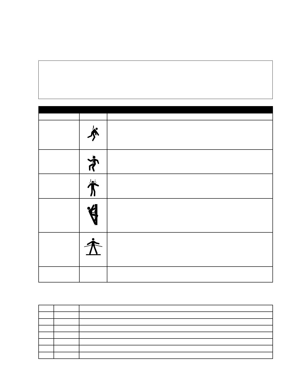
CSA Z259.10 requirements. See Figure 3 for application illustrations.
WARNING: Working at height has inherent risks. Some risks are noted here but are not limited to:
falling, suspension/prolonged suspension, striking objects, and unconsciousness. In the event of a fall
arrest and/or subsequent rescue (emergency) situation, some personal medical conditions may affect your
safety. Medical conditions identi ed as risky for this type of activity include, but are not limited to: heart
disease, high blood pressure, vertigo, epilepsy, drug or alcohol dependence, psychiatric illness, impaired
limb function and balance issues. We recommend that your employer/physician determine if you are t to
handle normal and emergency use of this equipment.
Table 1 - ExoFit NEX™ Full Body Harness Applications
Application CSA Class Description
Personal Fall Arrest Class A
The full body harness is used as a component of a personal fall arrest system.
Personal fall arrest systems typically include a full body harness and a connecting
subsystem (energy absorbing lanyard). Maximum arresting force must not exceed
1,800 lbs (8 kN). For fall arrest applications connect the fall arrest subsystem
(example: lanyard, SRL, energy absorber, etc.) to the D-ring or attachment element
on your back, between your shoulder blades.
Controlled Descent Class D
For controlled descent applications, harnesses equipped with a single sternal level
D-ring, one or two frontal mounted D-rings, or a pair of connectors originating
below the waist (such as a seat sling) may be used for connection to a descender or
evacuation system (reference in Z259.10 in Canada).
Rescue Class E The full body harness is used as a component of a rescue system. Rescue systems
are con gured depending on the type of rescue. For limited access (con ned space)
applications, harnesses equipped with D-rings on the shoulders may be used for
entry and egress into con ned spaces where worker pro le is an issue.
Ladder Climbing Class L
The full body harness is used as a component of a climbing system to prevent
the user from falling when climbing a ladder or other climbing structure. Climbing
systems typically include a full body harness, vertical cable or rail attached to the
structure, and climbing sleeve. For ladder climbing applications, harnesses equipped
with a frontal D-ring in the sternal location may be used for fall arrest on xed
ladder climbing systems. These are de ned in CSA Z259.2.1 in Canada and ANSI
A14.3 in the United States.
Work Positioning Class P
The full body harness is used as a component of a work positioning system to
support the user at a work position. Work positioning systems typically include a full
body harness, positioning lanyard, and a back-up personal fall arrest system. For
work positioning applications, connect the work positioning subsystem (example:
lanyard, Y-lanyard, etc.) to the lower (hip level) side or belt mounted work
positioning attachment anchorage elements (D-rings). Never use these connection
points for fall arrest.
Restraint None The full body harness is used as a component of a restraint system to prevent the
user from reaching a fall hazard. Restraint systems typically include a full body
harness and a lanyard or restraint line.
1.2 STANDARDS: Refer to local, state, and federal (OSHA) requirements governing occupational safety for
additional information regarding Personal Fall Arrest Systems. Refer to the following national standards on fall
protection:
ANSI Z359.0 De nitions and Nomenclature Used for Fall Protection and Fall Arrest
ANSI Z359.1 Safety Requirements for Personal Fall Arrest Systems, Subsystems, and Components
ANSI Z359.2 Minimum Requirements for a Comprehensive Managed Fall Protection Program
ANSI Z359.3 Safety Requirements for Positioning and Travel Restraint Systems
ANSI Z359.4 Safety Requirements for Assisted-Rescue and Self-Rescue Systems, Subsystems, and Components
ANSI A10.32 Fall Protection Systems for Construction and Demolitions
CSA Z259.10 Full Body Harnesses
ASTM F887-2011 Standard Speci cations for Personal Climbing Equipment
4
Figure 3 - Applications
1 Fall Arrest
2 Restraint
3 Ladder Climbing
4a Work Positioning
4b Work Positioning or
Controlled Descent,
with Seat Sling
4c Work Positioning,
with Seat Sling
4d Work Positioning,
with Seat Sling -
Tower Climbing
A Anchorage
B Anchorage
Connector
C Connecting
Subsystem (SRL
shown)
D Full Body Harness
E Restraint Lanyard
F Backup Fall Arrest
System
G Ladder
H Cable Sleeve
I Cable
J Seat Sling
K Tower Structure
1
A
B
C
D
2
A
B
A
E
3
G
H
I
D
E
F
B
A
A
B
D
4a 4b 4c 4d
D
A
B
F
A
B
F
A
J
J
J
K
E
D D
E
E
1.3 TRAINING: This equipment is intended to be used by persons trained in its correct application and use. It is the
responsibility of the user to assure they are familiar with these instructions and are trained in the correct care and use
of this equipment. Users must also be aware of the operating characteristics, application limits, and the consequences of
improper use.
2.0 SYSTEM LIMITATIONS & REQUIREMENTS
Consider the following limitations/requirements prior to installing or using this equipment:
2.1 CAPACITY: ExoFit NEX™ Full Body Harnesses are designed for use by persons with a combined weight
(clothing, tools, etc.) of no more than 420 lbs. (191 kg) per OSHA, 310 lbs. (141 kg) per ANSI Z359.1,
or 352 lbs. (160 kg) per CSA Z259.10-06. Make sure all of the components in your system are rated to a
capacity appropriate to your application.
2.2 FREE FALL: Personal fall arrest systems used with this equipment must be rigged to limit the free fall to 6
feet (1.8 M) per ANSI Z359.1 (see Section 7.1). Restraint systems must be rigged so that no vertical free
fall is possible. Work positioning systems must be rigged so that free fall is limited to 2 feet (.6 m) or less.
Personnel riding systems must be rigged so that no vertical free fall is possible. Climbing systems must
be rigged so that free fall is limited to 18 in. (.46 cm) or less. Rescue systems must be rigged so that no
vertical free fall is possible. See subsystem manufacturer’s instructions for more information.
2.3 FALL CLEARANCE: Figure 4 illustrates fall clearance requirements. There must be suf cient clearance
below the user to allow the system to arrest a fall before the user strikes the ground or other obstruction.
Clearance required is dependent on the following factors:
Elevation of Anchorage Connecting Subsystem Length
Deceleration Distance Free Fall Distance
Worker Height Movement of Harness Attachment Element
5
Figure 4 - Fall Clearance (Lanyards)
RD = LL + DD + HH + C
RD Required Fall Clearance Distance
LL Length of Lanyard (Speci ed on labeling)
DD Deceleration Distance = 4 ft (1.2 m) except:
for ANSI/OSHA Lanyards with Free Fall
greater than 6 ft (1.8 m) up to 12 ft (3.7
m), or user weights greater than 310 lbs
(141 kg) up to 420 lbs (191 kg); add 1 ft
(0.3 m): DD = 5 ft (1.5 m)
for CSA E6 Lanyards, add 1.7 ft. (0.5 m):
DD = 5.7 ft (1.7 m)
HH Height of Suspended Worker
C Safety Factor = 1.5 ft (0.5 m)
(Factors in D-Ring Slide and Harness Stretch.)
Example: Assuming a 6 ft (1.8 m) tall user with a
typical 6 ft (1.8 m) lanyard with 6 ft (1.8 m) Free Fall,
Fall Clearance calculation would be as follows:
RD = LL + DD + HH + C
RD = 6 ft + 4 ft + 6 ft + 1.5 ft = 17.5 ft
RD = 1.8 m + 1.2 m + 1.8 m + 0.5 m = 5.3 m
RD
LL
DD
HH
C
Figure 5 - Swing Falls
2.4 SWING FALLS: Swing falls occur when the anchorage point is not directly above the point where a fall
occurs. The force of striking an object in a swing fall may cause serious injury or death. Minimize swing
falls by working as close to the anchorage point as possible. Do not permit a swing fall if injury could occur.
Swing falls will signi cantly increase the clearance required when a self-
retracting lifeline or other variable
length connecting subsystem is used.
2.5 EXTENDED SUSPENSION:
A full body harness is not intended for use in extended suspension applications.
If the user is going to be suspended for an extended length of time it is recommended that some form of
seat support be used. DBI-SALA recommends a seat board, suspension work seat, seat sling, or a boatswain
chair. Contact Capital Safety for more information on these items.
2.6 ENVIRONMENTAL HAZARDS: Use of this equipment in areas with environmental hazards may require
additional precautions to prevent injury to the user or damage to the equipment. Hazards may include,
but are not limited to: heat, chemicals, corrosive environments, high voltage power lines, gases, moving
machinery and sharp edges.
2.7 COMPATIBILITY OF COMPONENTS: Unless otherwise noted, DBI-SALA equipment is designed for use with
DBI-SALA approved components and subsystems only. Substitutions or replacements made with non approved
components or subsystems may jeopardize compatibility of equipment and may affect safety and reliability of the
complete system.
2.8 COMPATIBILITY OF CONNECTORS: Connectors are considered to be compatible with connecting
elements when they have been designed to work together in such a way that their sizes and shapes do not
cause their gate mechanisms to inadvertently open regardless of how they become oriented. Connectors
(hooks, carabiners, and D-rings) must be capable of supporting at least 5,000 lbs. (22 kN). Connectors
must be compatible with the anchorage or other system components. Do not use equipment that is not
compatible. Non-compatible connectors may unintentionally disengage (see Figure 6). Connectors must
be compatible in size, shape, and strength. Self-locking snap hooks and carabiners are required by ANSI
Z359.1 and OSHA.
6
2.9 MAKING CONNECTIONS: Use only self-locking snap hooks and carabiners with this equipment. Only use
connectors that are suitable to each application. Ensure all connections are compatible in size, shape and
strength. Do not use equipment that is not compatible. Ensure all connectors are fully closed and locked.
DBI-SALA connectors (snap hooks and carabiners) are designed to be used only as speci ed in each
product’s user’s instructions. See Figure 7 for illustration of the inappropriate connections stated below. DBI-
SALA snap hooks and carabiners should not be connected:
A. To a D-ring to which another connector is attached.
B. In a manner that would result in a load on the gate.
C. In a false engagement, where features that protrude from the snap hook or carabiner catch on the
anchor and without visual con rmation seems to be fully engaged to the anchor point.
D. To each other.
E. Directly to webbing or rope lanyard or tie-back (unless the manufacturer’s instructions for both the
lanyard and connector speci cally allow such a connection).
F. To any object which is shaped or dimensioned such that the snap hook or carabiner will not close and
lock, or that roll-out could occur.
G. In a manner that does not allow the connector to align with the fall arrest device (i.e., lanyard) while
under load.
NOTE: Other than 3,600 lb. (16 kN) gated hooks, large throat opening snap hooks should not be
connected to standard size D-rings or similar objects which will result in a load on the gate if the hook or
D-ring twists or rotates. Large throat snap hooks are designed for use on xed structural elements such as
rebar or cross members that are not shaped in a way that can capture the gate of the hook.
Other Restrictions:
Do not make connections where the hook locking mechanism can come into contact with a structural
member or other equipment and potentially release the hook.
Do not connect a snap hook into a loop or thimble of a wire rope or attach in any way to a slack wire
rope.
The snap hook must be free to align with the applied load as intended (regardless of the size or shape of
the mating connector).
A carabiner may be used to connect to a single or pair of soft loops on a body support such as a body
belt or full body harness, provided the carabiner can fully close and lock. This type of connection is not
allowed for snap hooks.
A carabiner may be connected to a loop or ring connector that is already occupied by a choker style
connector. This type of connection is not allowed for snap hooks.
Figure 6 - Unintentional Disengagement (Rollout)
If the connecting element to which a snap hook (shown) or carabiner
attaches is undersized or irregular in shape, a situation could occur
where the connecting element applies a force to the gate of the snap
hook or carabiner. This force may cause the gate (of either a self-
locking or a non-locking snap hook) to open, allowing the snap hook
or carabiner to disengage from the connecting point.
Small ring or other
non-compatibly
shaped element
1. Force is applied
to the Snap
Hook.
2. The Gate
presses against
the Connecting
Ring.
3. The Gate opens
allowing the
Snap Hook to
slip off.
Figure 7 - Inappropriate Connections
7
2.10 CONNECTING SUBSYSTEMS: Connecting subsystems (self-retracting lifeline, lanyard, rope grab and
lifeline, cable sleeve) must be suitable for your application (see Table 1). See subsystem manufacturers
instructions for more information. Some harness models have web loop connection points. Do not use snap
hooks to connect to web loops. Use a self-locking carabiner to connect to a web loop. Ensure the carabiner
cannot cross-gate load (load against the gate rather than along the backbone of the carabiner). Some
lanyards are designed to choke onto a web loop to provide a compatible connection. See Figure 8. Lanyards
may be sewn directly to the web loop forming a permanent connection. Do not make multiple connections
onto one web loop, unless choking two lanyards onto a properly sized web loop.
Figure 8 - Web Loop Connection
1. Insert Lanyard Web Loop (A) through Web Loop
or D-ring on harness (B).
2. Insert opposite end of Lanyard through the
Lanyard Web Loop.
3. Pull the Lanyard through the connecting Web
Loop to secure.
B
A
1
2
3
2.11 ANCHORAGE & ANCHORAGE STRENGTH: Anchorage and anchorage strength requirements are dependent
on the full body harness application (see Figure 3). In accordance with ANSI Z359.1, anchorages selected for Fall
Arrest Systems must meet the anchorage strength requirements de ned in Table 2.
Table 2 - Anchorage Strength Requirements
Fall Arrest
1
Non-Certi ed Anchorages: 5,000 lbs (22.2 kN)
Certi ed Anchorages
2
: 2 times the Maximum Arresting Force for Certi ed
Anchorages
Restraint
1
Non-Certi ed Anchorages 1,000 (4,5 kN)
Certi ed Anchorages
2
: 2 times the foreseeable force for certi ed anchorages.
Work Positioning
1
Non-Certi ed Anchorages 3,000 lbs (13.3 kN)
Certi ed Anchorages
2
: 2 times the foreseeable force for certi ed anchorages.
Rescue
1
Non-Certi ed Anchorages 3,000 lbs (13.3 kN)
Certi ed Anchorages
2
: 5 times the foreseeable force for certi ed anchorages.
Climbing The structure to which a climbing system is attached must sustain the loads required by that
particular system. See the instructions for the climbing system for requirements.
1 Multiple Systems:
When more than one of the de ned system is attached to an anchorage, the strength de ned for Non-Certi ed
or Certi ed anchorages shall be multiplied by the number of systems attached to the anchorage.
2 Certi ed Anchorage: An anchorage for fall arrest, positioning, restraint, or rescue systems that a quali ed person certi es to be
capable of supporting the potential fall forces that could be encountered during a fall or that meet the criteria for a certi ed anchor-
age prescribed in this standard.
8
3.0 DONNING AND USE
WARNING: Do not alter or intentionally misuse this equipment. Consult Capital Safety when using this
equipment in combination with components or subsystems other than those described in this manual. Some
subsystem and component combinations may interfere with the operation of this equipment. Use caution when
using this equipment around moving machinery, electrical and chemical hazards, and sharp edges.
3.1 BEFORE EACH USE: Before each use of this equipment inspect the ExoFit NEX™ Full Body Harness
according to Section 5 of this manual.
3.2 PLANNING: Plan your system before use. Consider all factors that will affect your safety during use of this
equipment. Consider the following aspects when planning your system:
• ANCHORAGE: Select an anchorage that meets the anchorage requirements speci ed in Section 2.
• SHARP EDGES: Avoid working where system components may be in contact with, come in contact with,
or abrade against, unprotected sharp edges.
AFTER A FALL: Any equipment which has been subjected to the forces of arresting a fall, or exhibits
damage consistent with the effect of fall arrest forces as described in Section 5, must be removed from
service immediately and destroyed by the user, the rescuer
1
, or an authorized person
2
.
• RESCUE: The employer must have a rescue plan when using this equipment. The employer must have
the ability to perform a rescue quickly and safely.
3.3 DONNING AND FITTING THE HARNESS: The ExoFit NEX™ Full Body Harness is available in Vest
(Figure 1) and Cross-Over (Figure 10) styles. Donning procedures will vary with the harness style.
WARNING: Do not alter or intentionally misuse this equipment. Consult Capital Safety when using this
equipment in combination with components or subsystems other than those described in this manual. Some
subsystem and component combinations may interfere with the operation of this equipment. Use caution when
using this equipment around moving machinery, electrical and chemical hazards, and sharp edges.
Figure 9 - Vest Style Harness Figure 10 - Cross-Over Style Harness
A
A
A. Belt Loops A. Belt Loops
1 Rescuer: Person or persons other than the rescue subject acting to perform an assisted rescue by operation of a rescue
system.
2 Authorized Person: A person assigned by the employer to perform duties at a location where the person will be exposed to
a fall hazard (otherwise referred to as “user” for the purpose of these instructions).
9
A. EXOFIT NEX™ VEST STYLE FULL BODY HARNESS: The ExoFit NEX™ Vest Style Harness
incorporates loops for a removable waist belt (see Figure 9). The belt can be installed through the two
loops in the harness located in the lower back shoulder straps. The belt will pass through the harness
just below the padded area. The hip pad, if used, is secured to the belt by passing the belt through the
hip pad loops. Don the Vest Style Full Body Harness per the following steps and corresponding images in
Figure 11:
Step 1. Locate back D-ring held in position by the D-ring pad; lift up harness and hold by this
D-ring. Ensure the straps are not twisted.
Step 2. Grasp the shoulder straps and slip the harness onto one arm. The D-ring will be located on
your back side. Ensure that the straps are not tangled and hang freely. Slip your free arm
into the harness and position the shoulder straps on top of your shoulder. Ensure that the
straps are not tangled and hang freely. The chest strap, with quick connect buckle, will be
positioned on the front side when worn properly.
Step 3. Reach between your legs and grasp the gray leg strap on your left side. Bring the strap up
between your legs and connect it by inserting the tab of the buckle into receptor of quick
connect buckle on the left side as shown in Figure 11. You will hear a click when the tab
engages properly. Connect the right leg strap using the same procedure. To adjust the
leg straps, unlock
the webbing lock on the quick connect buckle and pull on the strap.
A plastic end keeper on the end of the strap will stop it from pulling completely out of the
buckle. When the strap is properly adjusted, lock the webbing lock. To release the buckle,
press the silver-colored tabs on the buckle towards each other with one hand, while pulling
on the tab portion of the buckle with the other hand.
NOTE: Locking and unlocking the webbing lock prevents or allows the strap to slide
between the sliding bar and slot on the female end of the quick connect buckle. It does
not control engagement or disengagement of the buckle ends and will not affect the
buckle connection in the event of a fall.
Step 4. Attach the chest strap by inserting the tab of the buckle into the receptor of the quick
connect buckle. You will hear a click when the tab engages properly. The chest strap should
be 6 in. (15 cm) down from the top of your shoulders. Pass excess strap through the loop
keepers. To adjust the chest strap, unlock
the webbing lock on the quick connect buckle
and pull on the strap. A plastic end keeper on the end of the strap will stop it from pulling
completely out of the buckle. When the strap is properly adjusted, lock the webbing lock.
To release the buckle, press the silver-colored tabs on the buckle toward each other with
one hand, while pulling on the tab portion of the buckle with the other hand.
Step 5. Adjust shoulder straps to a snug t with the Vertical Torso Adjusters (see Figure 11): Left
and right sides of shoulder straps should be adjusted to the same length and the chest strap
should be centered on your lower chest, 6 in. (15 cm) down from shoulder. The front D-ring
on the vest style harness is moved up or down by adjusting the shoulder straps and leg
straps. Center the back D-ring between your shoulder blades. Note: On applicable models,
the back (dorsal) D-ring can be repositioned up or down as needed for a correct t. Adjust
leg straps to a snug t. At least 3 in. (8 cm) of webbing must extend past the buckle on the
leg straps. Adjust the waist belt (if present).
10
Figure 11 - Donning the ExoFit NEX™ Vest Style Full Body Harness
Step 1 Step 2 Step 3
Step 4
Duo-Lok™ Quick Connect Buckles
Connection: Connect buckle ends by inserting
the tab into the receptor until a click is heard.
Strap Adjustment: Rotate Webbing Lock
to unlocked position
. Pull strap to adjust.
Rotate Webbing Lock to locked position
.
NOTE: The Webbing Lock does not control
engagement or disengagement of the buckle ends.
Revolver™ Vertical Torso Adjusters
Right
A
To Tighten: Turn
Ratchet Knob in
direction A.
To Loosen: Pull
Ratchet Knob
out and turn in
direction B.
NOTE: After
adjustment, tug
upwards on the
shoulder straps to
ensure that each
adjustor is locked in
place.
Left
A
B
B
Step 5
11
B. EXOFIT NEX™ CROSS-OVER STYLE FULL BODY HARNESS: The ExoFit NEX™ Cross-Over Style
Harness incorporates loops for a removable waist belt. The belt can be installed through the two loops
in the harness located in the lower back shoulder straps (see Figure 10). The belt will pass through the
harness just below the padded area. The hip pad, if used, is secured to the belt by passing the belt
through the hip pad loops. Don the Cross-Over Style Full Body Harness per the following steps and
corresponding images in Figure 12:
Step 1. Locate the back D-ring held in position by the D-ring pad; lift up the harness and hold by
this D-ring. Ensure the straps are not twisted.
Step 2.
Grasp the shoulder straps between the back and front D-ring and slip the harness over your
head from the left side. Position the shoulder straps on top of your shoulders. Ensure that
the straps are not tangled and hang freely. The D-ring will be positioned on your back when
worn properly.
Step 3. Grasp the tab of the buckle located at your right hip and insert it into the receptor of the
quick connect buckle (see Figure 12). You will hear a click when the tab engages properly.
Step 4. Reach between your legs and grasp the gray leg strap on your left side. Bring the strap up
between your legs and insert the tab of the buckle into the receptor of the buckle on the left
side as shown in Figure 12. You will hear a click when the tab engages properly. Connect
the right leg strap using the same procedure. To adjust the leg straps, unlock the webbing
lock on the quick connect buckle and pull on the strap. A plastic end keeper on the end of
the strap will stop it from pulling completely out of the buckle. When the strap is properly
adjusted, lock the webbing lock.
To release the buckle, press the silver-colored tabs on the
buckle towards each other with one hand, while pulling on the tab portion of the buckle with
the other hand.
NOTE: Locking and unlocking the webbing lock prevents or allows the strap to slide
between the sliding bar and slot on the female end of the quick connect buckle. It does
not control engagement or disengagement of the buckle ends and will not affect the
buckle connection in the event of a fall.
Step 5. Adjust shoulder straps to a snug t with the Vertical Torso Adjusters (see Figure 12):
Left and right sides of the shoulder straps should be adjusted to the same length and the
front D-ring should be centered on your lower chest. The back D-ring should be centered
between your shoulder blades. Note: On ExoFit XP models, the back (dorsal) D-ring can
be repositioned up or down as needed for a correct t. Adjust the leg straps to a snug t.
At least 3 in. (8 cm) of webbing must extend past the buckle on the leg straps. Adjust the
waist belt (if present).
3.4 USE OF FALL ARREST D-RING OR ATTACHMENT ELEMENT: For fall arrest applications connect to the
D-ring or attachment element on your back, between your shoulder blades. Side D-rings, if present, are for
positioning or restraint applications only. Front D-ring, if present, is for ladder climbing, positioning, or other
applications with a limited free fall not exceeding 2 feet (0.6 m) with a 900 MAF requirement. For rescue,
back, shoulder, or front D-rings may be used. D-rings on seat sling are for work positioning or personnel
riding.
3.5 MAKING CONNECTIONS: When using a hook to connect to an anchorage or when coupling components
of the system together, ensure roll-out cannot occur. Roll-out occurs when interference between the hook
and mating connector causes the hook gate to unintentionally open and release. Self-locking snap hooks
and carabiners should be used to reduce the possibility of roll-out. Do not use hooks or connectors that
will not completely close over the attachment object. See subsystem manufacturer’s instructions for more
information on making connections.
3.6 CONNECTING SYSTEM COMPONENTS: After properly tting the full body harness, the user may then
connect to other system components. Follow the guidelines in Section 3.4 when selecting the correct
attachment element.
12
Figure 12 - Donning the ExoFit NEX™ Cross-Over Style Full Body Harness
Step 1 Step 2 Step 3
Step 4
Duo-Lok™ Quick Connect Buckles
Connection: Connect buckle ends by inserting the
tab into the receptor until a click is heard.
Strap Adjustment: Rotate Webbing Lock to
unlocked position
. Pull strap to adjust. Rotate
Webbing Lock to locked position
.
NOTE: The Webbing Lock does not control
engagement or disengagement of the buckle ends.
Revolver™ Vertical Torso Adjusters
To Tighten: Turn Ratchet Knob in
direction A.
To Loosen: Pull Ratchet Knob out
and turn in direction B.
NOTE: After adjustment, tug
upwards on the shoulder straps to
ensure that each adjustor is locked
in place.
Left
A
B
Step 5
13
3.7 SUSPENSION TRAUMA STRAP: The
ExoFit NEX™ Full Body Harness is equipped with
a Suspension Trauma Strap (Figure 13) to help
prolong allowable suspension time in the event
of a fall from height. It should only be used
in situations where a fall has occurred or for
training. To use the Suspension Trauma Strap:
Step 1. Unzip the Trauma Strap Pouch on each
hip of the harness and deploy the
Suspension Straps (Figure 13A).
Step 2. Raise the ends of the straps to access
the hook and loops. Insert the hook
into the loop that provides the desired
strap length.
Step 3. Lower the Suspension Strap and step
onto the strap to alleviate pressure
of the harness leg straps on the legs
(Figure 13B). Adjust the hook/loop
combination for optimal comfort.
WARNING: Maintain an upright position
following suspension. Do not lay down. Seek
medical attention following a suspension.
Figure 13 - Suspension Trauma Straps
A
B
3.8 EXOFIT NEX GLOBAL WIND ENERGY
HARNESS MODEL REPLACEABLE LUMBAR
PROTECTOR: The Lumbar Protector (A) can be
replaced in the eld when worn or damaged. (See
Figure 14)
Place the ExoFit harness on a at surface. Pull the
hip belt (B) completely out of the harness to free
the worn/damaged Lumbar Protector (A) and tool
loops (D, if installed).
Figure 14 - Replaceable Lumbar Protector
A
B
To install the replacement Lumbar Protector:
Step 1. Reinsert the hip belt through the left
D-Ring (C), the end of the rst tool
loop (D, if installed), belt loops (E) and
(F), and the end of the tool loop (D).
C
D
E
D
F
Step 2. Insert the hip belt through the
replacement Lumbar Protector (G), the
second tool loop (H, if installed), the
next two belt loops (I) and (K), the
end of the tool loop (H) and the right
D-Ring.
I
H
G
H
K
Completed installation of replacement Lumbar
Protector.
14
4.0 TRAINING
It is the responsibility of the purchaser and the user of this equipment to assure that they understand these
instructions and are trained in the correct care and use of this equipment. They must also be aware of the
operating characteristics, application limits, and the consequences of improper use of this equipment.
IMPORTANT: Training must be conducted without exposing the user to a fall hazard. Training should be
repeated on a periodic basis.
5.0 INSPECTION
5.1 i-Safe™ RFID TAG: The i-Safe™ RFID tag on the ExoFit NEX™ Harness (see “Figure 15 i-Safe™ RFID Tag”)
can be used in conjunction with the i-Safe handheld reading device and the web based portal to simplify
inspection and inventory control and provide records for your fall protection equipment.
Figure 15 i-Safe™ RFID Tag
A Wrap-Around Cover
B i-Safe™ RFID Tag
C Product Labels
A
B
C
5.2 FREQUENCY: Before each use inspect the full body harness according to Section 5.3. The harness must
be inspected by a competent person
3
, other than the user, at least annually. Record the results of each
formal inspection in the inspection and maintenance log in section Section 9, or use the i-Safe™ inspection
web portal to maintain your inspection records. If you are a rst-time user, contact a Customer Service
representative in the US at 800-328-6146 or in Canada at 800-387-7484 or if you have already registered,
go to: www.capitalsafety.com/isafe. Follow instructions provided with your i-Safe handheld reader or on the
web portal to transfer your data to your web log.
IMPORTANT: If the full body harness has been subjected to fall arrest or impact forces it must be
immediately removed from service and destroyed.
IMPORTANT: Extreme working conditions (harsh environments, prolonged use, etc.) may require
increasing the frequency of inspections.
5.3 INSPECTION: Inspect the ExoFit NEX™ Full Body Harness as follows:
Step 1. Inspect harness hardware (buckles, D-rings, pads, loop keepers, vertical torso
adjusters): These items must not be damaged, broken, distorted, and must be free of sharp
edges, burrs, cracks, worn parts, or corrosion. PVC coated hardware must be free of cuts, rips,
tears, holes, etc. in the coating to ensure non-conductivity. Ensure that release tabs on buckles
work freely and that a click is heard when the buckle engages. Inspect vertical torso adjusters for
proper operation. Ratchet knobs should turn with ease in a clockwise direction and should only
turn counterclockwise when the knob is pulled out.
Step 2. Inspect webbing: Material must be free of frayed, cut, or broken bers. Check for tears,
abrasions, mold, burns, or discoloration. Inspect stitching; check for pulled or cut stitches. Broken
stitches may be an indication that the harness has been impact loaded and must be removed
from service. When performing the annual formal inspection, unsnap and open the back pad to
facilitate inspection of the webbing.
Step 3. Inspect the labels: All labels should be present and fully legible (see Section 8).
Step 4. Inspect system components and subsystems: Inspect each system component or subsystem
according to manufacturer’s instructions.
3 Competent Person: One who is capable of identifying existing and predictable hazards in the surroundings or working
conditions which are unsanitary, hazardous, or dangerous to employees, and who has authorization to take prompt corrective
measures to eliminate them.
15
Step 5. Record inspection data: Record the inspection date and results in the Inspection and
Maintenance Log (see Section 9).
Step 6. Inspect the Stitched Impact Indicator: The stitched impact indicator is a section of webbing
that is lapped back on itself and secured with a speci c stitch pattern holding the lap (see
Figure 16). The stitch pattern is designed to release when the harness arrests a fall or has been
subjected to an equivalent force If the impact indicator has been activated the harness must be
removed from service and destroyed.
Step 7. Inspect Suspension Trauma Straps: Check the trauma strap pouches for damage and secure
connection to the harness. Unzip the trauma strap pouch on each hip of the harness and inspect
suspension trauma straps. Webbing and pouch material must be free of frayed, cut, or broken
bers. Check for tears, abrasions, mold, burns, discoloration, or knots. Verify that one pouch is
marked ‘Hook’ and the other marked ‘loop’.
IMPORTANT: If inspection reveals a defective condition, remove the unit from service immediately and
destroy it.
NOTE: Only DBI-SALA or parties authorized in writing may make repairs to this equipment.
Figure 16- Stitched Impact Indicator
A. Stitched Impact Indicator
A
A
6.0 MAINTENANCE, SERVICING, AND STORAGE
6.1 WASHING INSTRUCTIONS: Washing procedures for the ExoFit NEX™ Full Body Harness are as follows:
Step 1. Spot clean the ExoFit NEX™ full body harness with water and a mild soap solution.
IMPORTANT: Use a bleach-free detergent when washing the harness and pads. Fabric softener or dryer
sheets SHOULD NOT be used when laundering and drying the harness and pads.
Step 2. Water temperature for wash and rinse must not exceed 160° F (70° C).
Step 3. The harness and pads may be air dried or tumble dried on low heat not exceeding 200° F (90° C).
NOTE: More information on cleaning is available from Capital Safety. If you have questions concerning the
condition of your harness, or have any doubt about putting it into service, contact Capital Safety.
6.2 ADDITIONAL MAINTENANCE AND SERVICING: Additional maintenance and servicing procedures must
be completed by a factory authorized service center. Authorization must be in writing. Do not attempt to
disassemble the unit.
6.3 STORAGE: Store the ExoFit NEX™ Full Body Harness in a cool, dry, clean environment out of direct sunlight.
Avoid areas where chemical vapors may exist. Thoroughly inspect the full body harness after extended
storage.
16
7.0 SPECIFICATIONS
7.1 PERFORMANCE:
Maximum Free Fall Distance: No greater than 6 ft (1.8 m), per federal law and ANSI Z359.1.
NOTE: Harness is acceptable for use with free fall distances exceeding 6 feet (1.8 m) if used with
appropriate connecting system.
Maximum Arresting Force: 1,800 lbs. (13 kN)
• Maximum Capacity:
• 420 lbs. (191 kg) per OSHA
• 310 lbs. (141 kg) per ANSI Z359.1
• 352 lbs. (160 kg) per CSA Z259.10-06
• Approximate Weight:
Harness only: 3 lbs. (1.4 kg)
Harness with Side D-rings: Add 1/2 lb. (.23 kg)
Harness with Front D-ring: Add 1/4 lb. (.11 kg)
Harness with Back Pad or Belt: Add 1 lb. (.45 kg)
7.2 MATERIALS:
• Webbing Materials: 6,000 lbs (27 kN) Polyester; 7,000 lbs (31 kN) Tensile Strength Nylon; 7,000 lbs
Tensile Strength Nomex
4
covered Kevlar
4
Pad and Label Cover Materials:
• Blend of Nylon and Polyester.
• All outer fabric is Nomex and Kevlar blend fabric. (Arc Flash models only)
• Fire Resistant Hook and Loop Fasteners. (Arc Flash models only)
• Optional Accessories:
• Hip Pad with side D-rings
• Nomex
®
covered Kevlar
®
webbing
• Non-sparking/ Non-conductive PVC coated hardware
• Arc-rated hip, leg, and back pads
• Polyurethane coated, arc-rated dorsal web loop
7.3 STANDARDS: When installed and used per the requirements and recommendations in the manual, the
ExoFit NEX™ Full Body Harness meets local, state, and federal requirements de ned in Section 1.2.
4 ®: Nomex
®
and Kevlar
®
are registered trademarks of DuPont.
17
8.0 LABELING
The following labels must be securely attached and fully legible:
All Models
ANSI Models CSA Models
18
ANSI Models CSA Models
Vest Style Harness
Cross-Over Style Harness
19
9.0 INSPECTION AND MAINTENANCE LOG
SERIAL NUMBER:
MODEL NUMBER:
DATE PURCHASED: DATE OF FIRST USE:
INSPECTION DATE INSPECTION ITEMS
NOTED
CORRECTIVE ACTION MAINTENANCE
PERFORMED
Approved By:
Approved By:
Approved By:
Approved By:
Approved By:
Approved By:
Approved By:
Approved By:
Approved By:
Approved By:
Approved By:
Approved By:
Approved By:
Approved By:
Approved By:
Approved By:
Approved By:
Approved By:
20
INSPECTION AND MAINTENANCE LOG
SERIAL NUMBER:
MODEL NUMBER:
DATE PURCHASED: DATE OF FIRST USE:
INSPECTION DATE INSPECTION ITEMS
NOTED
CORRECTIVE ACTION MAINTENANCE
PERFORMED
Approved By:
Approved By:
Approved By:
Approved By:
Approved By:
Approved By:
Approved By:
Approved By:
Approved By:
Approved By:
Approved By:
Approved By:
Approved By:
Approved By:
Approved By:
Approved By:
Approved By:
Approved By:
  • Page 1 1
  • Page 2 2
  • Page 3 3
  • Page 4 4
  • Page 5 5
  • Page 6 6
  • Page 7 7
  • Page 8 8
  • Page 9 9
  • Page 10 10
  • Page 11 11
  • Page 12 12
  • Page 13 13
  • Page 14 14
  • Page 15 15
  • Page 16 16
  • Page 17 17
  • Page 18 18
  • Page 19 19
  • Page 20 20
  • Page 21 21
  • Page 22 22
  • Page 23 23
  • Page 24 24

DBI-SALA DBI-SALA® ExoFit NEX™ Oil and Gas Positioning/Climbing Harness 1113293, X-Large, 1 EA Operating instructions

Type
Operating instructions

Ask a question and I''ll find the answer in the document

Finding information in a document is now easier with AI