Page is loading ...

© Copyright 2016, DBI Industries, Inc.
USER INSTRUCTION MANUAL
PRO™ Pack
420 Lbs. Capacity
Energy Absorbing Lanyards
Lanyards With integraL energy absorbers Used in PersonaL FaLL arrest systems
This manual should be used as part of an employee training program as required by OSHA.
Please read this User Instruction Manual
carefully before installing and using this product
.
danger: This product is part of a personal fall arrest, restraint or rescue system. Working at height creates inherent and
unavoidable risks which can result in serious injury or death. The user must follow the manufacturer’s instructions for each
component of the system. These instructions must be provided to the user of this equipment. The user must read and
understand these instructions before using this equipment. Manufacturer’s instructions must be followed for proper use and
maintenance of this equipment. Alterations or misuse of this product or failure to follow instructions may result in serious
injury or death.
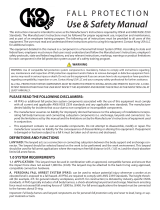
Figure 1 -
PRO™ Pack Energy Absorbing Lanyards
Hook
PRO Pack
Lanyard
Model
Energy
Absorber End
Hook
Lanyard
End Hook
A Steel Snap Hook
B Steel Rebar Snap Hook
1341010 A (1) A (1)
1341011 A (1) B (1)
1342010 A (1) A (2)
1342011 A (1) B (2)
Lanyard
End Hook
Energy
Absorber
End Hook
desCriPtion:
Figure 1 identies the PRO™ Pack 420 lbs. capacity Energy Absorbing Lanyard models covered by this instruction manual.
imPortant: If you have questions on the use, care, or suitability of this equipment for your application, contact
Capital Safety.
imPortant: Before using this equipment, record the product identication information from the ID label in the “Inspection
and Maintenance Log” in this instruction document.
Form No: 5903919 Rev: A
Trusted Quality Fall Protection

2
1.0 APPLICATIONS
1.1 PURPOSE: PRO™ Pack Energy Absorbing Lanyards and Energy Absorbers are intended to be used as part of a personal
fall arrest system. Applications include activities where the possibility of a fall exists. See Figure 1 for the energy
absorbing lanyard models covered by this instruction. Energy absorbing lanyards are used in the following applications:
Fall Arrest: Fall arrest systems safely stop the user in a free fall from a height. The user can
then self-rescue or be rescued. Personal fall arrest systems typically include a full body harness
and an energy absorbing lanyard. Maximum arresting force must not exceed 1,800 lbs (8 kN).
Restraint: Restraint systems prevent the user from reaching a fall hazard (example: leading
edge roof work).
Rescue: The energy absorbing lanyard is used as a component of a back-up fall protection
system during rescue or as part of the primary rescue system.
1.2 LIMITATIONS AND REQUIREMENTS:
wArNINg: Always consider the following application limitations and requirements before using this equipment.
A. CAPACITY: The PRO™ Pack
Energy Absorbing Lanyard
is designed for use by persons with a combined weight
(clothing, tools, etc.) of no more than 420 lbs. (191 kg). Make sure all of the components in your system are rated to
a capacity appropriate to your application.
B. FREE FALL: Personal fall arrest systems incorporating this equipment must be rigged to limit the free fall to 6 feet
(1.8 m) or less when using PRO™ Pack energy absorbing lanyards.
C. FALL CLEARANCE: There must be sufcient clearance below the user to arrest a fall before the user strikes the
ground or other obstruction. The clearance required depends on several factors:
• Deployment distance • Energy absorbing lanyard length • Movement of harness attachment element
• Free fall distance • Elevation of anchorage • Worker height
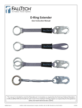
Figure 2 illustrates fall clearance calculation for an energy absorbing lanyard.
D. SWING FALLS: Swing falls occur when the anchorage point is not directly above the point where a fall occurs (see
Figure 3). Minimize swing falls by working as close to and directly below the anchorage point as possible. Do not
permit a swing fall if injury could occur.
wArNINg: The force of striking an object in a swing fall may cause serious injury or death.
Figure 2 – Fall Clearance Figure 3 – Swing Falls
RD = LL + DD + HH + C
RD Required Fall Clearance Distance
LL Length of Lanyard (Specied on labeling)
DD Deployment Distance = 4 ft (1.2 m)
HH Height of Suspended Worker
C Safety Factor = 1.5 ft (0.5 m)
(Factors in D-Ring Slide and Harness Stretch.)
Example: Assuming a 6 ft (1.8 m) tall user with a
typical 6 ft (1.8 m) lanyard with 6 ft (1.8 m) Free Fall,
Fall Clearance calculation would be as follows:
RD = LL + DD + HH + C
RD = 6 ft + 4 ft + 6 ft + 1.5 ft = 17.5 ft
RD = 1.8 m + 1.2 m + 1.8 m + 0.5 m = 5.3 m
RD
LL
DD
HH
C
Swing
Fall
Hazard
E. ENVIRONMENTAL HAZARDS: Use of this equipment in areas containing physical or environmental hazards may
require that additional precautions be taken to reduce the possibility of damage to this equipment or injury to the
user. Hazards may include, but are not limited to: high heat, strong or caustic chemicals, corrosive environments,
the possibility of electric current owing through this equipment when working near high voltage power lines,
explosive or toxic gases, moving machinery, or sharp edges. Contact Capital Safety if you have any questions about
the application of this equipment
F. TRAINING: It is the responsibility of the user and the purchaser of this equipment to assure that they are familiar
with these instructions, trained in the correct care and use of, and are aware of the operating characteristics,
application limits, and the consequences of improper use of this equipment.
IMPOrTANT: Training must be conducted without exposing the trainee to a fall hazard. Training should be
repeated on a periodic basis.

3
G. SHARP EDGES: Avoid working where system components may be in contact with, or abrade against, unprotected
sharp edges. Do not loop lanyard around small diameter structural members. If working with this equipment near
sharp edges is unavoidable, protection against cutting must be provided by using a heavy pad or other means over
the exposed sharp edge.
1.3 APPLICABLE STANDARDS: Refer to applicable local, state, and federal (OSHA) requirements governing occupational
safety for more information on Energy Absorbing Lanyards, Energy Absorbers and associated components.
1.4 RESCUE PLAN: When using this equipment, the employer must have a rescue plan and the means at hand to implement
the rescue, as well as communicate that plan to users, authorized persons, and rescuers.
1.5 INSPECTION BEFORE USE: The energy absorbing lanyard must be inspected according to
procedures in Section 4 of this
instruction manual.
2.0 SySTeM requIreMeNTS
2.1 COMPATIBILITY OF COMPONENTS: PROTECTA equipment is designed for use with Capital Safety approved
components and subsystems only. Substitutions or replacements made with non-approved components or subsystems
may jeopardize compatibility of equipment and may effect the safety and reliability of the complete system.
2.2 COMPATIBILITY OF CONNECTORS:
IMPOrTANT: Use only connectors that are suitable to each application and are compatible with connecting elements.
• Connectors must be compatible with the anchorage or other system components.
• Connectors must be compatible in size, shape, and strength.
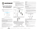
• Non-compatible connectors may unintentionally disengage (see Figure 4).
Connectors are considered to be compatible with connecting elements when they have been designed to work together in
such a way that their sizes and shapes do not cause their gate mechanisms to inadvertently open regardless of how they
become oriented. Do not use equipment that is not compatible. Contact Capital Safety if you have any questions about
compatibility. Connectors (hooks, carabiners, and D-Rings) must be capable of supporting at least 5,000 lbs. (22.2 kN).
2.3 MAKING CONNECTIONS: PROTECTA connectors (snap hooks and carabiners) are designed to be used only as specied
in each product’s user’s instructions. See Figure 5 for inappropriate connections.
PROTECTA snap hooks and carabiners should not be connected:
A. To a D-Ring to which another connector is attached.
B. In a manner that would result in a load on the gate.
wArNINg: Large throat snap hooks should not be connected to standard size D-Rings or similar objects which will result in a
load on the gate if the hook or D-Ring twists or rotates, unless the snap hook complies with ANSI Z359.12 and is equipped with a
3,600 lb (16 kN) gate. Check the marking on your snap hook to verify that it is appropriate for your application.
C. In a false engagement, where features that protrude from the snap hook or carabiner catch on the anchor, and
without visual confirmation seems to be fully engaged to the anchor point.
D. To each other.
E. Directly to webbing or rope lanyard or tie-back (unless the manufacturer’s instructions for both the lanyard and
connector specifically allows such a connection).
F. To any object which is shaped or dimensioned such that the snap hook or carabiner will not close and lock, or that
roll-out could occur.
G. In a manner that does not allow the connector to align properly while under load.
CAuTION: Ensure all connectors are fully closed and locked.
Figure 4 – Unintentional Disengagement Figure 5 – Inappropriate Connections
If the connecting element to which a snap hook (shown) or carabiner attaches
is undersized or irregular in shape, a situation could occur where the connecting
element applies a force to the gate of the snap hook or carabiner. This force may
cause the gate (of either a self-locking or a non-locking snap hook) to open,
allowing the snap hook or carabiner to disengage from the connecting point.
Small ring or other
non-compatibly
shaped element
Force is applied to the
Snap Hook.
The Gate presses against
the Connecting Ring.
The Gate opens allowing
the Snap Hook to slip off.
A. B. C. D.
E. F. G.

4
2.4 WEB LOOP CONNECTIONS: See Figure 6. Insert the
energy absorbing lanyard web loop through the harness
web loop or D-Ring. Insert the opposite end of the energy
absorbing lanyard through the lanyard web loop. Pull the
attached energy absorbing lanyard through the lanyard
web loop to secure it.
2.5 ANCHORAGE STRENGTH: Anchorages selected for use
with the energy absorbing lanyards must have a strength
capable of sustaining the static load requirements of the
intended fall protection application:
A. Fall Arrest: Anchorages selected for personal fall
arrest systems (PFAS) shall have a strength capable
of sustaining static loads applied in the directions
permitted by the system of at least:
1. Two times the arresting force for certied
anchorages
1
, or
2. 5,000 pounds (22.2 kN) for non-certied
anchorages.
When more than one fall arrest system is attached to
an anchorage, the strengths set forth in (1) and (2)
above shall be multiplied by the number of systems
attached to the anchorage.
Figure 6 – Web Loop Connection
1. Insert the lanyard web loop through the web loop or D-Ring on the harness.
2. Insert the appropriate end of the lanyard through the lanyard web loop.
3. Pull the lanyard through the connecting web loop to secure.
wArNINg: Anchorages must be rigid. Large deformations of the anchorage will affect system performance, and may increase
the required fall clearance below the system, which could result in serious injury or death.
From OSHA 1926.502 and 1910.66: Anchorages used for attachment of PFAS must be independent of any anchorage
being used to support or suspend platforms and must be capable of supporting at least 5,000 lbs. (22.2 kN) per each
attached user. Or, be designed, installed, and used as part of a complete PFAS which maintains a safety factor of at
least two, and is supervised by a qualied person.
3.0 OPerATION AND uSe
wArNINg: Do not alter or intentionally misuse this equipment. Consult Capital Safety when using this equipment
in combination with components or subsystems other than those described in this manual. Some subsystem and
component combinations may interfere with the operation of this equipment. Use caution when using this equipment
around moving machinery, electrical hazards, chemical hazards, sharp edges, or overhead materials that may fall
onto the lanyard. Do not loop the lanyard around small structural members. Failure to heed this warning may result in
equipment malfunction, serious injury, or death.
wArNINg: Consult your doctor if there is reason to doubt your tness to safely absorb the shock from a fall arrest.
Age and tness seriously affect a worker’s ability to withstand falls. Pregnant women or minors must not use any
PROTECTA fall protection equipment.
3.1 BEFORE EACH USE of this equipment, inspect it according to “Inspection Checklist” (Table 1).
3.2 PLAN your system before use. Consider all factors that will affect your safety during use of this equipment. The following
list gives important points to consider when planning your system:
A. ANCHORAGE: Select an anchorage that meets the requirements specified in “System Requirements”.
B. SHARP EDGES: Avoid working where system components may be in contact with, or abrade against, unprotected
sharp edges.
C. AFTER A FALL: Components which have been subjected to the forces of arresting a fall must be removed from
service and destroyed. See the “Inspection and Maintenance Log.”
D. RESCUE: The employer must have a rescue plan when using this equipment. The employer must have the ability to
perform a rescue quickly and safely.
wArNINg: Read and follow manufacturer’s instructions for associated equipment (full body harness, rope grab, etc.)
used in your fall protection system.
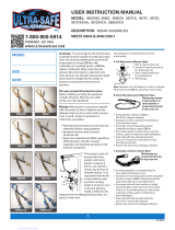
3.4 CONNECTING TO BODY SUPPORT AND ANCHORAGE OR ANCHORAGE CONNECTOR: See Figure 7. Energy
absorbing lanyards should be connected to the body support rst and then connected to the rest of the system. Always
connect the energy absorber end of the lanyard to
the D-Ring on the back between the shoulders (dorsal D-Ring) on a
full body harness.
Capital Safety does not recommend using a body belt for fall arrest applications. If using a body belt,
connect the energy absorbing end of the lanyard to the D-Ring and position the belt so the D-Ring is located on the back
side of the body.
Connect the lanyard end to the anchorage or anchorage connector. Some anchorage connector devices may be supplied
with a permanently attached energy absorber. Use of an additional energy absorber or energy absorbing lanyard with this
lanyard system is not recommended.
1 Certied Anchorage:
An anchorage for fall arrest, restraint or work positioning that a qualied person certies to be capable of supporting the potential fall
forces that could be encountered during a fall or that meet the criteria for certied anchorage prescribed by the associated standard(s).

5
Figure 7 – Anchorage Connection Examples
A Dorsal D-Ring, Full Body Harness
B Energy Absorbing Lanyard
C Anchorage Connector
D Fall Arrestor
E Anchorage
Figure 5 –
E
C
C
B
D
A AA
B
B
E
E
3.5 A. 100% TIE-OFF LANYARD CONSIDERATIONS: Commonly known as 100% tie-off, “Y” type, twin leg, or double
lanyards; these energy absorbing lanyards can be used to provide continuous fall protection while ascending,
descending, or moving laterally. With one lanyard leg attached, the worker can move to a new location, attach
unused lanyard leg, and disconnect attached leg. This procedure is repeated until a new location is reached.
Other practices that must be followed in order to use a 100% tie-off type lanyard safely include:
1. The energy absorber portion of the lanyard must be connected to the dorsal D-Ring only. Use only the snap hook
(or other connector provided) to attach the energy absorber portion directly to the harness dorsal D-Ring. See
Figures 8 and 9.
2. Do not connect the energy absorber to the anchorage. See Figure 10.
Figure 8 – Correct Attachment Figure 9 – Incorrect
Attachment
Figure 10 – Incorrect
Attachment
Energy
Absorber
attached to
dorsal D-Ring.
Energy
Absorber
not attached
to dorsal
D-Ring.
Do not attach
Energy
Absorber to
anchor.
3. Do not attach the unused leg of the lanyard back to the harness at any location unless a specially designed
lanyard retainer is provided for this purpose. See Figure 11.
4. Connection of both lanyard legs to separate anchorage points is acceptable. See Figure 12.
5. When moving from one anchorage point to the next (such as traversing a horizontal or vertical structure) do not
connect to anchorage points that are farther apart than the lanyard length (as marked on the lanyard label).
See Figure 13.
6. Never connect more than one person to a “Y” type lanyard at a time.
7. Do not allow any lanyard to pass under arms or legs during use.
Figure 11 – Acceptable
Designed Retainers
Figure 12 – Acceptable
Attachment
Figure 13 – Maximum
Lanyard Reach
Energy absorber attached to dorsal D-Ring. Lanyard legs conneced to
separate anchorage points.
Do not attach to anchorage
points wider than lanyard length.

6
Attaching a Tie-Back Lanyard: See
Figure 14. Place the tie-back lanyard
over the anchoring structure. Ensure the
lanyard is not twisted. Adjust the floating
D-Ring so it hangs below the anchoring
structure. Attach the lanyard end hook to
the floating D-Ring.
Ensure the lanyard is cinched tight around
the anchorage during use.
B. ATTACHING A LANYARD WITH WEB
LOOPS: See Section 2.4
Figure 14 – Attaching Tie-Back
A Do not allow gate to contact
anchorage member.
B Proper Connection.
C Improper connection.
A
B
C
C. CONNECTING TO A ROPE GRAB (FALL ARRESTOR): It is recommended the lanyard end (vs. the energy absorber
end) be attached to the rope grab. This recommendation is made to reduce possible interference with the operation
of the rope grab by the energy absorber “pack.” Attaching a component style energy absorber to a rope grab is not
recommended, with the exception of a “direct-coupling” between a rope grab and a harness. Some rope grabs may
be supplied with a permanently attached energy absorbing lanyard. For these cases, use of an additional energy
absorber connected between the rope grab and the body support is not recommended.
In some cases it may be permissible to couple an energy absorber component between the anchorage (or anchorage
connector) and the rope grab lifeline. In all cases, ensure the length of the energy absorber or energy absorbing
lanyard does not exceed the rope grab manufacturer’s recommended maximum connection length (3 feet [.9 m]
maximum per ANSI Z359.1). Consult the manufacturer’s instructions provided with the Rope Grab for further details.
D. CONNECTING TO SELF RETRACTING LIFELINE: Capital Safety does not recommend connecting an energy
absorbing lanyard or energy absorber component to a self retracting lifeline. Special applications do exist where it
may be permissible. Contact Capital Safety if you are considering connecting an energy absorbing lanyard to a self
retracting lifeline.
3.6 AFTER USE, return the lanyard for cleaning or storage as described in section 5.0.
4.0 INSPeCTION
4.1 INSPECTION FREQUENCY:
The Energy Absorbing Lanyard shall be inspected by the user before each use and,
additionally, by a competent person
1
other than the user at intervals of no more than one year
2
. Inspection procedures are
described in the “Inspection Checklist” (Table 1). Results of each Competent Person inspection should be recorded on copies
of the “Inspection and Maintenance Log” (lanyards).
4.2 UNSAFE OR DEFECTIVE CONDITIONS: If inspection reveals an unsafe or defective condition, remove the lanyard from
service and destroy. Lanyards are not repairable.
4.3 PRODUCT LIFE: The functional life of the lanyard is determined by work conditions and maintenance. As long as the
lanyard passes inspection criteria, it may remain in service.
wArNINg: Failure to properly inspect the lanyard could result in product failure and serious injury or death.
Table 1 – Inspection Checklist
Component: Inspection: (See Section 4.2 for Inspection Frequency) Pass Fail
Lanyard Hardware Inspect energy absorbing lanyard or energy absorber component hardware
(snap hooks, adjusters, swages, thimbles, etc.). These items must not be
damaged, broken, distorted, or have any sharp edges, burrs, cracks, worn
parts, or corrosion. Ensure the connecting hooks work properly. Hook gates
must move freely and lock upon closing. Ensure adjusters (if present) work
properly.
Webbing & Stitching
(Figure 15)
The webbing material must be free of frayed, cut, or broken bers. Check
for tears, abrasions, mold, burns, or discoloration, etc. The webbing must be
free of knots, excessive soiling, heavy paint buildup, and rust staining. Check
for chemical or heat damage indicated by brown, discolored, or brittle areas.
Check for ultraviolet damage indicated by discoloration and the presence of
splinters or slivers on the webbing surface. All of the above factors are known
to reduce webbing strength. Inspect stitching for pulled or cut stitches. Broken
stitches may be an indication the energy absorbing lanyard or energy absorber
component has been impact loaded and must be removed from service.
Energy Absorber &
Impact Indication
(Figure 16)
Inspect the energy absorber to determine if it has been activated. There
should be no evidence of elongation. Ensure energy absorber cover is secure
and not torn or damaged.
Label Label should be present and fully legible (see Section 6 ‘Labels’).
System & Subsystem
Components
Inspect each system component or subsystem according to manufacturer’s
instructions and conrm that it can continue to be used.
2 Competent Person: One who is capable of identifying existing and predictable hazards in the surroundings or working conditions which are unsanitary, hazard-
ous, or dangerous to employees, and who has authorization to take prompt corrective measures to eliminate them.
3 Inspection Frequency: Extreme working conditions (harsh environments, prolonged use, etc.) may require increasing the frequency of competent person
inspections.

7
Table 1 – Inspection Checklist
Figure 15 - Webbing
Cut
Frayed
Heavily
Soiled
Welding
Burns
Figure 16 – Impact Indicators
The following items indicate the Energy Absorber has been subjected to impact
loading and has been activated:
1. Torn webbing.
2. Torn or broken cover.
3. Open end or ripped out stitching.
4. Measured length is more than 15 cm (6 in.) longer than the length marked on the
label.
4
1
2
3
3
5.0 MAINTeNANCe, SerVICINg, STOrAge
5.1 Clean lanyard with water and a mild detergent solution. Wipe off hardware with a clean, dry cloth, and hang to air dry. Do
not force dry with heat. An excessive buildup of dirt, paint, etc., may prevent the lanyard from working properly, and in
severe cases degrade the webbing or rope to a point where it has become weakened and should be removed from service.
If you have any questions concerning the condition or cleaning of your lanyard, doubts about putting it into service or
require more information, contact Capital Safety.
5.2 Additional maintenance and servicing procedures (replacement parts) must be completed by a factory authorized service
center. Authorization must be in writing. Do not disassemble the unit. See Section 4.1 for inspection frequency.
5.3 Store the lanyard in a cool, dry, clean environment out of direct sunlight. Avoid areas where chemical vapors may exist.
Thoroughly inspect the lanyard or energy absorber component after extended storage.
6.0 LAbeLS This label must be securely attached to the lanyard and fully visible.
INSPeCTION AND MAINTeNANCe LOg
SERIAL NUMBER:
MODEL NUMBER:
DATE PURCHASED: DATE OF FIRST USE:
INSPECTION DATE INSPECTION ITEMS
NOTED
CORRECTIVE ACTION MAINTENANCE
PERFORMED
Approved By:
Approved By:
Approved By:
Approved By:

ISO
9001
USA
3833 SALA Way
Red Wing, MN 55066-5005
Toll Free: 800.328.6146
Phone: 651.388.8282
Fax: 651.388.5065
solutions@capitalsafety.com
Brazil
Rua Anne Frank, 2621
Boqueirão Curitiba PR
81650-020
Brazil
Phone: 0800-942-2300
brasil@capitalsafety.com
Mexico
Calle Norte 35, 895-E
Col. Industrial Vallejo
C.P. 02300 Azcapotzalco
Mexico D.F.
Phone: (55) 57194820
mexico@capitalsafety.com
Colombia
Compañía Latinoamericana de Seguridad S.A.S.
Carrera 106 #15-25 Interior 105 Manzana 15
Zona Franca - Bogotá, Colombia
Phone: 57 1 6014777
servicioalcliente@capitalsafety.com
Canada
260 Export Boulevard
Mississauga, ON L5S 1Y9
Phone: 905.795.9333
Toll-Free: 800.387.7484
Fax: 888.387.7484
info.ca@capitalsafety.com
EMEA (Europe, Middle East, Africa)
EMEA Headquarters:
5a Merse Road
North Moons Moat
Redditch, Worcestershire
B98 9HL UK
Phone: + 44 (0)1527 548 000
Fax: + 44 (0)1527 591 000
csgne@capitalsafety.com
France:
Le Broc Center
Z.I. 1re Avenue - BP15
06511 Carros Le Broc Cedex
France
Phone: + 33 04 97 10 00 10
Fax: + 33 04 93 08 79 70
information@capitalsafety.com
Australia & New Zealand
95 Derby Street
Silverwater
Sydney NSW 2128
Australia
Phone: +(61) 2 8753 7600
Toll-Free : 1800 245 002 (AUS)
Toll-Free : 0800 212 505 (NZ)
Fax: +(61) 2 8753 7603
sales@capitalsafety.com.au
Asia
Singapore:
69, Ubi Road 1, #05-20
Oxley Bizhub
Singapore 408731
Phone: +65 - 65587758
Fax: +65 - 65587058
inquiry@capitalsafety.com
Shanghai:
Rm 1406, China Venturetech Plaza
819 Nan Jing Xi Rd,
Shanghai 200041, P R China
Phone: +86 21 62539050
Fax: +86 21 62539060
inquiry@capitalsafety.cn
www.capitalsafety.com
LIMITED LIFETIME WARRANTY
Warranty to End User: D B Industries, Inc., dba CAPITAL SAFETY USA (“CAPITAL SAFETY”)
warrants to the original end user (“End User”) that its products are free from defects in materials and
workmanship under normal use and service. This warranty extends for the lifetime of the product
from the date the product is purchased by the End User, in new and unused condition, from a CAPITAL
SAFETY authorized distributor. CAPITAL SAFETY’S entire liability to End User and End User’s exclusive
remedy under this warranty is limited to the repair or replacement in kind of any defective product
within its lifetime (as CAPITAL SAFETY in its sole discretion determines and deems appropriate). No oral
or written information or advice given by CAPITAL SAFETY, its distributors, directors, offi cers, agents
or employees shall create any different or additional warranties or in any way increase the scope of
this warranty. CAPITAL SAFETY will not accept liability for defects that are the result of product abuse,
misuse, alteration or modifi cation, or for defects that are due to a failure to install, maintain, or use the
product in accordance with the manufacturer’s instructions.
CAPITAL SAFETY’S WARRANTY APPLIES ONLY TO THE END USER. THIS WARRANTY IS THE ONLY
WARRANTY APPLICABLE TO OUR PRODUCTS AND IS IN LIEU OF ALL OTHER WARRANTIES AND
LIABILITIES, EXPRESSED OR IMPLIED. CAPITAL SAFETY EXPRESSLY EXCLUDES AND DISCLAIMS
ANY IMPLIED WARRANTIES OF MERCHANTABILITY OR FITNESS FOR A PARTICULAR PURPOSE, AND
SHALL NOT BE LIABLE FOR INCIDENTAL, PUNITIVE OR CONSEQUENTIAL DAMAGES OF ANY NATURE,
INCLUDING WITHOUT LIMITATION, LOST PROFITS, REVENUES, OR PRODUCTIVITY, OR FOR BODILY
INJURY OR DEATH OR LOSS OR DAMAGE TO PROPERTY, UNDER ANY THEORY OF LIABILITY, INCLUDING
WITHOUT LIMITATION, CONTRACT, WARRANTY, STRICT LIABILITY, TORT (INCLUDING NEGLIGENCE) OR
OTHER LEGAL OR EQUITABLE THEORY.
/