Page is loading ...

R7 EXPERT / PRO | SERVICE & TRAVEL GUIDE


3
R7 EXPERT / PRO SERVICE GUIDE
This manual is intended to provide the information necessary to service the
Manitou R7 Expert and Pro Suspension fork. We highly recommend any service
or installation be performed by a qualied mechanic. These instructions can be
downloaded from the Hayes Bicycle Group website at
www.hayesbicycle.com
INTRODUCTION
We highly recommend that service to this component be performed by a certied
bicycle mechanic. Failure to follow instructions presented in this manual could
lead to serious injury or death. Any questions about the servicing of product or
the manual itself should be directed to Hayes Customer Support at:
WARNING
! !
Hayes
Bicycle
USA
5800 W Donges Bay Road Mequon WI 53092
Phone: 888.686.3472
Email: techsupport@hayesbicycle.com
Hayes
Bicycle
Europe
Dirnismaning 20 a 85748 Garching (b. Munich) Germany
Phone: +49 89 203237450
Email: techsupportEU@hayesbicycle.com
Hayes
Bicycle
Asia
16F, No. 37, Sec. 3 Mincyuan E. Rd. Zhongshan District
Taipei City 10476 Taiwan ROC
Phone: 886-2-2518-1108

4
R7 EXPERT / PRO SERVICE GUIDE
table of contents
SECTION PAGE NUMBER
Tools And Materials 5
Casting Removal & Service 6–8
Air Spring Service 9–11
Damper Service 12–15
Casting Install 16–18
Compression Damper Install 19–21
Recommended Starting Pressure 22
Travel Change 23
Exploded Views 24–31

5
R7 EXPERT / PRO SERVICE GUIDE
tools and materials
• Safety Glasses
• Nitrile Gloves
• Lint-Free Rags
• Slickoleum™ Grease
10-Oz Tub – Manitou Part Number 20-32929
5Ml Tube – Manitou Part Number 141-33604-K001
• Semi-Bath Oil, 5/40W Synthetic
Manitou Part Number 85-0022
• 5W Maxima Fork Oil
Manitou Part Number 85-0023
• 32mm Seal Press
Manitou Part Number 172-31122
• 32mm Rebuild Kit
Manitou Part Number 141-28528-K010
• Manitou Tool Kit – Manitou Part Number 172-31133
(Includes The 3 Tools Below)
Manitou Slotted Cassette Tool
Manitou Thin Walled 8mm Socket
Manitou 24mm Flat Ground Socket
• 2mm Hex Wrench
• 4mm Hex Wrench
• 6mm Hex Wrench
• 8mm Socket
• 11mm Socket
• 22mm Wrench, Open or Box End
• Torque Wrench
• Park Tool FR-5.2 Cassette Lockring Tool, or similar
• 1” Socket, for use with Park Tool FR-5.2 Cassette Lockring Tool
• Socket Wrench
• 22mm Crow’s Foot
• Fork/Shock Pump
• Pick
• Adjustable Wrench
• Downhill Tire Lever Or Flat Blade Screwdriver
• Support Block (2”x4”x4” Wood, Plastic, or Similar)

6
R7 EXPERT / PRO SERVICE GUIDE
CASTING REMOVAL & SERVICE
1
Holding the rebound knob steady,
insert 2mm hex wrench into
rebound knob screw and rotate
the wrench counter-clockwise until
threads completely disengage.
Remove rebound knob and screw.
Insert an 8mm Hex wrench into
the end of the rebound rod and
rotate clockwise. The rebound
end tting will move toward the
inside of the casting. Continue
rotating until end tting disengages
completely from casting threads.
2
3
Unscrew air cap and depress
Schrader valve a few times to
ensure all air is released.
Do not proceed to next
step without completely
depressurizing air spring
CAUTION

7
R7 EXPERT / PRO SERVICE GUIDE
Insert Manitou 8mm Thin Wall
Socket onto the end of the
compression rod and rotate
clockwise. The comp rod end
tting will move toward the inside
of the casting. Continue rotating
until end tting disengages
completely from casting threads.
Remove casting from fork. It is
recommended this be done over
a drain pan as the lower casting
contains semi-bath oil. Allow oil
in casting to drain out before
continuing to next step.
4
5
6
Using a downhill tire lever or similar
tool, gently pry the dust seals out
of the casting.
CASTING REMOVAL & SERVICE
Note: the compression rod can also be loosened
by using an 8mm box end wrench on the external
hex and a 4mm hex wrench on the internal
hex of the comp rod end tting. Rotating both
wrenches clockwise simultaneously will loosen the
compression rod, reducing the risk of damaging a
seized end tting.

8
R7 EXPERT / PRO SERVICE GUIDE
CASTING REMOVAL & SERVICE
8
7
Remove old foam wiper rings. Clean
seal area with isopropyl alcohol.
Apply semi-bath uid to the new
foam wiper rings and install into
fork casting.
Remove springs from lip of dust
seals. Using the Manitou 32mm Seal
Press or large socket, press in the
dust seals. Reinstall springs onto
seals.

9
R7 EXPERT / PRO SERVICE GUIDE
AIR SPRING SERVICE
1
2
3
Using Manitou 24mm Flat Ground
Socket, rotate air spring top cap
counter-clockwise and remove
when threads completely disengage
from the stanchion.
Invert the fork. Using a 22mm
wrench, rotate the air spring
end cap counter-clockwise until
threads completely disengage from
stanchion.
Remove air spring assembly. Clean
assembly with isopropyl alcohol
and a lint-free towel. Inspect air
spring shaft, bumpers, and air
piston seal for wear/damage and
replace if necessary.
Do not begin disassembly until
completely depressurizing air
spring.
CAUTION
Make sure to apply top down
force on tool to prevent slipping
NOTICE

10
R7 EXPERT / PRO SERVICE GUIDE
AIR SPRING SERVICE
5
6
Once the air spring assembly
is removed, clean the inside of
the stanchion with isopropyl
alcohol and a lint free towel.
Be careful to not scratch
the inner surface of the
stanchion. Inspect the inside
and outside of the stanchion
for scratches or other damage.
Liberally grease the piston quad
seal and outer surface with
Slickoleum™ grease. Also add 3cc’s
of Slickoleum™ grease to the top of
the air piston.
4
Add Slickoleum™ grease to the
stanchion threads before inserting
the air spring assembly. Spread
grease across entire thread
surface.

11
R7 EXPERT / PRO SERVICE GUIDE
7
8
Install air spring assembly into
stanchion. Rotating clockwise,
start the end cap threads by hand
to prevent cross-threading. Using
a 22mm crow’s foot and torque
wrench, torque to
80-100 in lb [9.0-11.3 N m].
AIR SPRING SERVICE
Install air spring top cap into
stanchion. Torque to 60-80 in lbs
[6.8-9.0 N m].
Make sure to apply top down force
on the tool to prevent slipping.
NOTICE

12
R7 EXPERT / PRO SERVICE GUIDE
DAMPER SERVICE
1a
1b
*PRO MODEL* Using a 2mm
hex wrench, rotate counter-
clockwise and remove open-mode-
adjust knob screw when threads
completely disengage from the
damper. Remove the open-mode-
adjust knob.
2
NOTICE
NOTICE
NOTICE
*PRO MODEL* Using an 11mm
socket, rotate counter-clockwise
and remove the knob lock nut when
the threads completely disengage
from the damper.
*Expert Model* Using a 2mm hex
wrench, rotate counter-clockwise
and remove knob screw when
threads completely disengage from
the damper.
For Expert, skip to step 2.
For Expert, skip to step 2.
For Pro, skip to step 3.

13
R7 EXPERT / PRO SERVICE GUIDE
Remove the black compression
knob and knob seal.
Rotating counter-clockwise, use
a standard cassette lockring tool,
such as Park Tool’s FR-5.2, with
the appropriate socket/wrench to
unthread the compression damper
assembly.
NOTICE
Non-standard spanners may
damage the damper’s splined
interface. Only use a standard
cassette lockring tool and apply a
top-down force while loosening to
prevent slipping.
DAMPER SERVICE
3
4
5
Remove compression damper
assembly from the stanchion.

14
R7 EXPERT / PRO SERVICE GUIDE
DAMPER SERVICE
6
7a
7b
Pour fork oil into a catch pan.
*PRO MODEL* Using the Manitou
slotted cassette tool and wrench,
rotate the damper end cap counter-
clockwise until threads completely
disengage from the stanchion.
NOTICE
For Expert, skip to step 7B
*EXPERT MODEL* Using a 22mm
wrench, rotate the damper end
cap counter-clockwise until threads
completely disengage from the
stanchion.
NOTICE
For Pro, skip to step 8

15
R7 EXPERT / PRO SERVICE GUIDE
DAMPER SERVICE
9
Remove rebound damper assembly
from the fork. Once the damper
assembly is removed, clean
the inside of the stanchion with
isopropyl alcohol and a lint free
towel. Inspect the inside and
outside of the stanchion for
scratches and other damage.
Inspect rebound damper for
damage and replace if necessary.
Install rebound damper assembly
into stanchion. Rotating clockwise,
start the end cap threads by hand
to prevent cross-threading.
*PRO MODEL* Use a 26mm crow’s
foot, Manitou slotted cassette tool,
and torque wrench to tighten to
60-80 in lbs [6.8-9.0 N m].
*EXPERT MODEL* Use a 22mm
crow’s foot and torque wrench to
tighten to 80-100 in lbs [9.0-11.3
N m].
8

16
R7 EXPERT / PRO SERVICE GUIDE
CASTING INSTALL
1
2
3
Apply a thin layer of either
Slickoleum grease or semi-bath
oil to the inside surface of the fork
seal.
Tightly assemble shock pump tting
to comp rod end tting. Inate the
air spring to 50 PSI. The air spring
should not move during ination.
With the shock pump still attached,
lightly pull the comp rod to full
extension so that some compression
of the internal top-out bumper can be
felt. Remove the shock pump. This
process will ease casting installation.
Lightly pull the rebound damper
rod to full extension.

17
R7 EXPERT / PRO SERVICE GUIDE
CASTING INSTALL
4
5
6
Slide the casting partially onto the
stanchion assembly, such that the
air spring and rebound end ttings
are not yet in contact with the
casting threads. Take care during
installation to not fold over fork
seal lips on the stanchions.
Insert 7cc of semi-bath into each
casting leg. Once the semi-bath is
in the legs, slide the casting the
rest of the way onto the stanchion
assembly.
Using an 8mm Hex wrench and
torque wrench, tighten the rebound
damper rod to 30–40 in lb [3.4–4.5
N m] by turning them counter-
clockwise. Do not overtighten, as
doing so can damage the end of
the rods.

18
R7 EXPERT / PRO SERVICE GUIDE
CASTING INSTALL
8
7
Using the Manitou 8mm Thin Wall
Socket and torque wrench, turn
the compression rod counter-
clockwise. Torque to
30-40 in lbs [3,4-4,5 N m].
Do not overtighten, as doing so can
damage the end of the rods.
Install rebound knob. Holding
the knob steady, use a 2mm hex
wrench to assemble the rebound
knob screw (rotating clockwise) and
torque to 0.5-0.7 in lb [4-6 N m].

19
R7 EXPERT / PRO SERVICE GUIDE
COMPRESSION DAMPER INSTALL
1
2
3
Fill the damper leg approximately
3/4 full with Maxima 5wt fork oil.
Install the axle into the fork without a
hub or wheel. Cover the damper leg
opening with a lint-free towel. Using
a wood block or similar raised support
underneath the axle, compress the
fork 10-15 times.
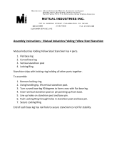
Pour additional 5wt fork oil into
the damper leg until the oil height
(space from the top of the damper
leg to the top of the oil) is set at
the proper level of 87mm. An
oil height setting tool used for
motorcycle forks similar to the one
pictured makes this job easier.
Oil
87mm
NOTICE
The raised support should be wide
enough and long enough to safely
support the axle as well as tall
enough to eliminate contact between
the oor and the comp rod end tting
or rebound knob. Do not overtighten
the axle bolt.

20
R7 EXPERT / PRO SERVICE GUIDE
4
5
6a
Rotate the adjuster hex on the
compression damper counter-
clockwise to the unlocked/open
position. Install the damper into the
fork.
Rotating clockwise, use a torque
wrench and a standard cassette
lockring tool, such as Park Tool’s
FR-5.2, with the appropriate socket
to torque the compression damper
assembly to 60-80 in-lbs [6.8-9.0
Nm].
*PRO MODEL* Install the knob seal
and adjuster knob. Holding the
knob steady, use an 11mm socket
and torque wrench to assemble the
knob lock nut (rotating clockwise)
and tighten to 0.5-0.7 in lbs [4-6 N
m].
COMPRESSION DAMPER INSTALL
NOTICE
NOTICE
Non-standard spanners may
damage the damper’s splined
interface. Only use a standard
cassette lockring tool and apply a
top-down force while loosening to
prevent slipping.
For Expert, skip to step 7
/