INSTALLATION INSTRUCTIONS
AUCKLAND
9 Levene Place, Mount Wellington
PO Box 12 249, Penrose, Auckland 1061
New Zealand
P +64 9 525 6051 F +64 9 525 5799
VYNCO INDUSTRIES (NZ) LIMITED
CHRISTCHURCH
388 Tuam Street, Phillipstown, Christchurch, 8011
PO Box 9022, Tower Junction, Christchurch 8149
New Zealand
P +64 3 379 9283 F +64 3 379 6838
VYNCO.CO.NZ
2CS1W / 2CS1B - CARD SWITCH
INSV0007
SPECIFICATIONS
Input Voltage 250V AC, 50Hz
Rated Current 16A Resistive
Minimum Load 0A
Contacts 1xN/0
SAFETY
This product must be installed with the card slot
facing upwards. Do not install horizontally or facing
downwards. This keycard switch is required to be
protected by a 16A MCB or RCBO.
This product complies in full with AS/NZS 606691.
This product should be installed by a suitably
qualied person in accordance with Australian
and New Zealand wiring rules.
IP20
WARRANTY
This product is covered by the standard 5 Year Vynco
Warranty - proof of purchase is required. Please
contact Vynco for details of returns procedure.
NOTE: This product contains NO user serviceable parts.
WIRING
L’ = Live or Phase - Brown or Red
N = Neutral - Blue or Black
LOAD = Load Live or Phase - Brown or Red
LOAD
N
N
LL
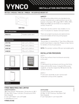
STEP 1
Card switch is designed for installation into a ush
box or similar location secured with two
xing screws.
STEP 2
Ensure the relevant circuits are isolated and safe
prior to installation.
STEP 3
Cut out ush box opening.
STEP 4
Terminate wiring to card switch.
STEP 5
Secure card switch into ush box with two securing
screws (supplied). Then clip on fascia cover.
INSTALLATION PROCEDURE
FINISH:
MATERIAL:
REVISION:
DESCRIPTION:
SHEET 2 OF 2
A3
SIZE
APPROVED BY:
PART No:
388 Tuam St
Christchurch
New Zealand
P:
03 379 9283
W:
vynco.co.nz
UNLESS OTHERWISE STATED ALL DIMENSIONS ARE IN MILLIMETRES
ALL CRITICAL TOLERANCES SPECIFIED IN DRAWING
NON SPECIFIED TOLERANCES:
LINEAR: 0.0 ±0.5 0.00 ±0.1 ANGULAR: ±0.5°
THE INFORMATION CONTAINED IN THIS DRAWING IS THE SOLE PROPERTY OF VYNCO INDUSTRIES
(N.Z.) LTD. ANY REPRODUCTION IN PART OR AS A WHOLE WITHOUT THE WRITTEN PERMISSION
OF VYNCO INDUSTRIES (N.Z.) LTD IS PROHIBITED.
DRAWN BY:
DRAWN DATE:
CHANGE BY:
CHANGE DATE:
APPROVED DATE:
A
01
DRAFT
2CS1
CARD SWITCH ASSEMBLY
-
-
soppitb
26/07/2019
-
-
16/05/2019
soppitb
DRAWING NOT TO SCALE
SWITCHING
Electronic switch activated with standard sized card,
specic card not required.
Switch On: Instant switching on insertion of card.
Switch Off: 1 minute after card is removed (time
interval not adjustable).


