Page is loading ...

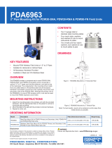
PDWR Wireless Signal Repeater
Instruction Manual
PRECISION DIGITAL CORPORATION
233 South Street • Hopkinton MA 01748 USA
Tel (800) 343-1001
www.predig.com
• Wireless Repeater Unit Improves Signal Strength and Range for PDW Wireless Systems
• Use in PDW30 Point to Point and PDW90 Point to Multi-Point Wireless Systems
• Increase Range an Additional 1 Mile Line-of-Sight, 500 Feet Indoor
• Increases Range of the Analog, Digital I/O and Modbus Signals
• Simple to Configure Using PDW Manager Programming Software and On-Board USB
• Use CapTouch Through-Glass Buttons to Change Network ID
• Device Communication Secured by Enabling 128-bit AES Encryption
• Password Protection
• IP68, NEMA 4X Aluminum & Stainless Steel Enclosures With Plenty of Room for Field Wiring
• Operating Temperature Range: -55 to 75°C (-67 to 167°F)
• Conformal Coated PCBs for Dust & Humidity Protection
• Flange for Wall or Pipe Mounting; Loop for Stainless Steel Tag; Holes for Tamper-Proof Seal
• 9-30 VDC Power
• 3-Year Warranty
Available in Aluminum
or Stainless Steel

PDWR Wireless Signal Repeater
Instruction Manual
2
Table of Contents
Introduction ......................................................................................................... 3
Key Features ....................................................................................................... 4
PDW Manager PC Software ........................................................................... 4
CapTouch Through-Glass Buttons ............................................................... 5
Repeater Units Available in Aluminum or Stainless Steel .......................... 5
Application Example .......................................................................................... 6
Extending Signal Range with PDWR Repeaters .......................................... 6
Ordering Information .......................................................................................... 7
Accessories .................................................................................................... 7
Specifications ..................................................................................................... 8
General ............................................................................................................ 8
Enclosure ........................................................................................................ 8
Wireless Radio ............................................................................................... 8
PDW Manager Software ................................................................................. 8
Safety Information .............................................................................................. 9
Unpacking ....................................................................................................... 9
Installation........................................................................................................... 9
Mounting Instructions .................................................................................... 9
Cover Jam Screw ........................................................................................... 9
FCC Notice ...................................................................................................... 9
Canada (IC) Notice ...................................................................................... 9
Dimensions ....................................................................................................... 10
PDWA6963-SS Stainless Steel Pipe Mounting Kit ......................................... 11
Connections ...................................................................................................... 12
Connector Labeling / Location .................................................................... 12
Wiring Diagram ............................................................................................. 12
Power Connections .................................................................................... 12
Setup and Programming .................................................................................. 13
Overview ....................................................................................................... 13
Buttons & Display ........................................................................................ 13
Programming Buttons ................................................................................. 13
CapTouch Buttons ....................................................................................... 14
CapTouch Button Tips ............................................................................... 14
PDW Manager Software ............................................................................... 14
Setup Menu ................................................................................................... 15
Entering Numeric Values ........................................................................... 15
Network ID ................................................................................................. 15
Password Setup ......................................................................................... 15
Restore Defaults ........................................................................................ 15
Programming with PDW Manager ............................................................... 16
Networking Settings and Security .............................................................. 17
Troubleshooting ............................................................................................... 18
Table of Figures
Figure 1. Enclosure & Antenna Dimensions – Front View ............................ 10
Figure 2. Enclosure Dimensions – Side View ................................................ 10
Figure 3. Enclosure Dimensions – Top View ................................................. 10
Figure 4. PDW Unit Mounted to Vertical Pipe with One PDWA6963-SS Kit . 11
Figure 5. PDW Unit Mounted to Horizontal Pipe with Two PDWA6963-SS Kits 11
Figure 6. PDWR Repeater Display Module Connectors ................................ 12
Figure 7. Power Connections .......................................................................... 12

PDWR Wireless Signal Repeater
Instruction Manual
3
Disclaimer
The information contained in this document is
subject to change without notice. Precision Digital
Corporation makes no representations or
warranties with respect to the contents hereof;
and specifically disclaims any implied warranties
of merchantability or fitness for a particular
purpose.
• Read complete instructions prior to installation
and operation of the device.
• Risk of electric shock or personal injury.
• This product is not recommended for life support
applications or applications where
malfunctioning could result in personal injury or
property loss. Anyone using this product for
such applications does so at their own risk.
Precision Digital Corporation shall not be held
liable for damages resulting from such improper
use.
• Failure to follow installation guidelines could
result in death or serious injury. Make sure only
qualified personnel perform the installation.
WARNING
Cancer and Reproductive Harm - www.P65Warnings.ca.gov
Limited Warranty
Precision Digital Corporation warrants this
product against defects in material or
workmanship for the specified period under
“Specifications” from the date of shipment from
the factory. Precision Digital’s liability under this
limited warranty shall not exceed the purchase
value, repair, or replacement of the defective unit.
See Warranty Information and Terms &
Conditions on www.predig.com for complete
details.
Registered Trademarks
Modbus® is a registered trademark of Schneider
Electric. All other trademarks mentioned in this
document are the property of their respective
owners.
© 2023 Precision Digital Corporation.
All rights reserved.
Introduction
PDWR wireless signal repeaters are used to improve
the connectivity in PDW30 point to point and PDW90
point to multi-point wireless systems. They will
generally increase signal range of the system by
another 1 mile line-of-sight or 500 feet indoor.
The repeaters are simple to install as they only
require power and a network ID. Any PDW wireless
units in range of the repeater with the same network
ID will retransmit through it, thus increasing signal
strength.
PDWR repeaters can be used to broadcast over very
long distances or around permanent obstacles.
The PDWR repeaters are available in either aluminum
or stainless steel NEMA 4X, IP68 enclosures and
these enclosures contain plenty of room for field
wiring connections.

PDWR Wireless Signal Repeater
Instruction Manual
4
Key Features
PDW Manager PC Software
PDW Manager PC Software allows for programming
the PDWR repeater units from a PC with a USB
connection. The units connect to a PC via the USB
connection on the side of the display module behind
the cover of the enclosure. Use of PDW Manager is
required for programming advanced settings such as
wireless encryption. PDW Manager is available for
download at www.predig.com/pdwmanager.
Easy-To-Install Display Module
The display module designed specifically for the
PDWR wireless units are easy to remove making it
convenient for wiring the unit. The display module is
completely enclosed for added protection when wiring
and handling.

PDWR Wireless Signal Repeater
Instruction Manual
5
CapTouch Through-Glass
Buttons
The PDWR repeater units are equipped with four
capacitive sensors that operate as through-glass
buttons so that they can be operated without
removing the cover (and exposing the electronics)
in an unclean area.
CapTouch buttons allow the Network ID to be pro-
grammed without removing the cover.
CapTouch buttons are designed to work under any
lighting condition and are not affected by random
changes in light or shadows. To protect against false
triggering a long button press of about 2 seconds is
required to wake up the buttons when they have not
been in use.
Repeater Units Available in
Aluminum or Stainless Steel
The PDWR repeater units are available in an IP68,
NEMA 4X aluminum or stainless steel enclosure. The
enclosures feature a built-in flange for wall or pipe
mounting, built-in loop for a stainless steel tag, locking
screw, and hole for a tamper-proof wire & seal. The
enclosure also includes two 3/4" threaded conduit
openings for wiring. The PDWR repeater units can
operate in temperatures of -55 to 75°C (-67 to 167°F).

PDWR Wireless Signal Repeater
Instruction Manual
6
Application Example
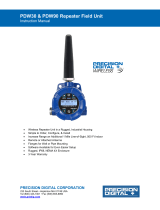
Extending Signal Range with PDWR Repeaters
The PDWR repeaters are used to retransmit wireless signals when connectivity between the PDW30 primary and
secondary units or the PDW90 base station and field units are out of range or are obstructed by other objects or
structures.
PDW30 Point-to-Point Wireless Bridge Using a Repeater to Extend the Signal Range
PDW90 Point to Multi-Point Wireless System Using a Repeater to Extend the Signal Range

PDWR Wireless Signal Repeater
Instruction Manual
7
Ordering Information
Model
Description
PDWR-GP-AL-REP
PDW30/PDW90 Repeater to
Extend Wireless Distance,
Aluminum Enclosure1
PDWR-GP-SS-REP
PDW30/PDW90 Repeater to
Extend Wireless Distance,
Stainless Steel Enclosure1
Accessories
Model
Description
PDA10
PDW Wireless Signal
Strength Survey Tool
PDWA3120-S
20' RP-SMA M/F
Extension Cable for
Omnidirectional Antenna2
PDWA3140-S
40' RP-SMA M/F
Extension Cable for
Omnidirectional Antenna2
PDWA3900-20-N
PDW 900 MHz
Omnidirectional Antenna,
M20
PDWA3900-34-N
PDW 900 MHz
Omnidirectional Antenna,
3/4" NPT
PDWA6963-SS
Stainless Steel Pipe Mount Kit
for One PDW30 Primary/
Secondary Unit, PDW90 Field
Unit or PDWR Repeater Unit3
PDAPLUG75
3/4" Metal Conduit/Stopping
Plug
PDAREDUCER-75M-50F
M-3/4" NPT to F-1/2" NPT
Reducer with Approvals
PDAREDUCER-75M-M20F
M-3/4" NPT to F-M20
Reducer with Approvals
PDA-MICROUSB
Micro-USB PC Programming
Cable for Field Unit (supplied)
PDA-SSTAG
Custom Stainless Steel Tag
(See website for convenient
ordering form)
Notes:
1. The PDWR repeater units come standard with two 3/4"
NPT conduit holes. To order models with M20 conduit
holes instead, add -22 at the end of the part number
(e.g. PDWR-GP-AL-REP-22)
2. Antenna extension cables include the following parts:
(1) Extension Cable, (1) Antenna Coupler, (1) 8" Length
of Coax Seal Tape, (1) 3/4" NPT Cable Gland
3. (2) Two PDWA6963-SS mounting kits are required for
mounting a PDW unit on a horizontal pipe.
PDWA6963-SS Pipe Mounting Kit
The PDWA6963-SS provides a convenient way to
mount one PDW30 primary/secondary, PDWR
repeater, or PDW90 field unit to a horizontal or
vertical 1.5" or 2" pipe such that the antenna is not
right on top of the metal pipe.
Model Number
Description
PDWA6963-SS
Stainless Steel Pipe Mount Kit for
One PDW30 Primary/Secondary
Unit, PDW90 Field Unit or PDWR
Repeater Unit
Note: (2) Two PDWA6963-SS mounting kits are required for
mounting a PDW unit on a horizontal pipe.
PDA10 Wireless Surveying Tool Kit
The handheld and target units are used to survey
wireless signal strength throughout nonhazardous ar-
eas of a facility prior to PDW30 or PDW90 equipment
installation. The target unit is set in a desired installa-
tion location and the handheld is brought to another
installation location. The handheld unit will provide an
indication of signal strength between the two units.
Model Number
Description
PDA10
PDW Wireless Signal Strength
Survey Tool Kit

PDWR Wireless Signal Repeater
Instruction Manual
8
Specifications
Except where noted all specifications apply to operation at +25°C.
General
Display
32-character dual-line alphanumeric dot
matrix LCD display with backlight
Visual Area: 2.54" x 0.63" (64.6 x 16.0 mm)
Character Height: 0.2" (5.5 mm)
Display used for programming assistance
and displaying communications link status
and signal strength.
Number of
Repeaters
Up to 3 repeaters per system
Network ID
Field selectable: 0 - 99
Peak Antenna
Gain
1.8 dBi +/- 1.0
Programming
Methods
Change network ID and factory defaults only.
Four CapTouch through-glass buttons or PC
with PDW Manager software.
Password
A programmable password restricts
modification of programmed settings.
Power
9-30 VDC, 1.0 W max
Non-Volatile
Memory
All programmed settings are stored in non-
volatile memory for a minimum of ten
years if power is lost.
Isolation
500 V
Environmental
Operating temp. range: -55 to 75°C
(display inoperable < -20 °C)
Storage temp. range: -55 to 85°C
Relative humidity:
0 to 90% non-condensing
Printed circuit boards are conformally
coated
Connections
Removable screw terminal blocks accept
12 to 26 AWG wire.
Connectors
Tightening
Torque
4.5 lb-in (0.5 Nm)
Mounting
May be mounted directly to conduit.
Built-in flange for 1.5" to 2" pipe or wall
mounting. See Dimensions on page 10 for
mounting space requirements.
Overall
Dimensions
5.25" x 11.63" x 4.80"
(133 x 295 x 122 mm)
(W x H x D)
Weight
Aluminum: 5.6 lbs (2.5 kg)
Stainless Steel: 9.8 lbs (4.4 kg)
Warranty
3 year parts and labor. See Warranty
Information and Terms & Conditions on
www.predig.com for complete details.
Enclosure
Material
-AL Models:
ASTM A413 LM6 die-cast aluminum,
copper-free, enamel coated.
-SS Models:
ASTM A743 CF8M investment-cast
316 stainless steel
Gasket
Fluoroelastomer
Rating
NEMA 4X, IP68
Color
-AL: Blue; -SS: Silver
Window
Borosilicate glass
Conduits
Three ¾" NPT threaded conduit openings;
One used for mounting the antenna (factory
installed), the other two available for field
wiring.
M20 conduits are available. See Ordering
Information on page 7 for details.
Flange
Built-in flange for wall and pipe mounting.
Tamper-
Proof Seal
Enclosure lid may be secured with
tamper-proof seal.
Instrument
Tag Loop
Built-in loop for securing stainless steel tag.
Wireless Radio
Frequency
900 MHz
Range
500 ft (152.4 m) indoor,
1 mi (1.61 km) outdoor (line-of-sight)
Encryption
AES 128-bit encryption available using
PDW Manager software
Interference
Reduction
Frequency Hopping Spread Spectrum
(FHSS)
Power Output
24 dBm (250 mW)
Sensitivity
-101 dBm
PDW Manager Software
System
Requirements
Microsoft® Windows® XP/Vista/7/8/10
Communications
USB 2.0; Micro-USB Type B
Configuration
Configure devices one at a time
Compatibility
The PDW Manager v2.00 is compatible
with firmware version 1.10; there is a
possibility of issues in the GUI (Graph-
ical User Interface), but it should not be
a problem configuring the supported
features.
Availability
Download from predig.com/pdwmanager

PDWR Wireless Signal Repeater
Instruction Manual
9
Safety Information
• Read complete instructions prior to installation
and operation of the device.
• Read all product labels completely and follow all
instructions and requirements listed on the
labels for installation or service.
• Installation and service should be performed
only by trained service personnel. Service
requiring replacement of internal components
must be performed at the factory.
Unpacking
Remove unit from box. Inspect the packaging and
contents for damage. Report damages, if any, to the
carrier. If any part is missing or the units malfunction,
please contact your supplier or the factory for assis-
tance.
Installation
To access the connectors, remove the enclosure
cover and unclip the display module by pulling it from
the enclosure. The display module may be discon-
nected from the option module (if installed) to facilitate
wiring to the relay option module.
Mounting Instructions
There are three ways to mount the PDWR repeater:
1. To a wall with the built-in flange
2. To a 1.5" or 2" pipe using the PDWA6963-SS
stainless steel pipe mounting kit as shown on
page 11.
3. Supported by the conduit using the conduit
holes provided.
The factory installed antenna is threaded into one of
the three conduit holes and may be moved as appro-
priate for the installation.
Cover Jam Screw
The cover jam screw should be properly installed
once the wireless units have been wired and tested in
a safe environment. The cover jam screw is intended
to prevent the removal of the units’ cover while in op-
eration without the use of tools. Using a M2 hex
wrench, turn the screw clockwise until the screw con-
tacts the unit. Turn the screw an additional 1/4 to 1/2
turn to secure the cover.
• Excess torque may damage the threads and/or
wrench.
FCC Notice
Contains FCC ID: MCQ-XB900HP
The enclosed device complies with Part 15 of the
FCC Rules. Operation is subject to the following two
conditions: (i.) this device may not cause harmful in-
terference and (ii.) this device must accept any inter-
ference received, including interference that may
cause undesired operation.
• The RF module has been certified for remote
and base radio applications. If the module will
be used for portable applications, the device
must undergo SAR testing. This equipment has
been tested and found to comply with the limits
for a Class B digital device, pursuant to Part 15
of the FCC Rules. These limits are designed to
provide reasonable protection against harmful
interference in a residential installation. This
equipment generates, uses and can radiate
radio frequency energy and, if not installed and
used in accordance with the instructions, may
cause harmful interference to radio
communications. However, there is no
guarantee that interference will not occur in a
particular installation.
• If this equipment does cause harmful
interference to radio or television reception,
which can be determined by turning the
equipment off and on, the user is encouraged to
try to correct the interference by one or more of
the following measures: Re-orient or relocate
the receiving antenna, Increase the separation
between the equipment and receiver. Connect
equipment and receiver to outlets on different
circuits or consult the dealer or an experienced
radio/TV technician for help.
Canada (IC) Notice
Contains Model: XB900HP, IC: 1846A-XB900HP
Integrator is responsible for its product to comply with
IC ICES-003 & FCC Part 15, Sub. B - Unintentional
Radiators. ICES-003 is the same as FCC Part 15
Sub. B and Industry Canada accepts FCC test
report or CISPR 22 test report for compliance with
ICES-003.

PDWR Wireless Signal Repeater
Instruction Manual
10
Dimensions
Figure 1. Enclosure & Antenna Dimensions – Front View
Figure 2. Enclosure Dimensions – Side View
Figure 3. Enclosure Dimensions – Top View

PDWR Wireless Signal Repeater
Instruction Manual
11
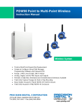
PDWA6963-SS Stainless Steel Pipe Mounting Kit
The PDWA6963-SS provides a convenient way to
mount PDW30, PDWR, and PDW90 wireless field
units to horizontal or vertical 1.5" or 2" pipes such that
the antenna is not right on top of the metal pipe.
The components in the mounting kit are made from
316 stainless steel and all necessary hardware is pro-
vided to mount one unit on a vertical pipe. To mount a
unit to a horizontal pipe, two kits are required.
Vertical Pipe Mounting
Horizontal Pipe Mounting
Mounting Instructions
1. Attach the mounting plate to the PDW wireless
unit with the provided hardware using the round
holes on the plate.
2. Mount the plate to the pipe with the provided
U-bolt / hardware using the slotted holes on the
mounting plate.
3. For best results, mount unit so antenna is as far
away from metal devices as possible.
4. Two PDWA6963-SS mounting kits are required
for mounting a PDW unit on a horizontal pipe.
Figure 4. PDW Unit Mounted to Vertical Pipe with
One PDWA6963-SS Kit
Figure 5. PDW Unit Mounted to Horizontal Pipe with
Two PDWA6963-SS Kits

PDWR Wireless Signal Repeater
Instruction Manual
12
Connections
To access the connectors, remove the enclosure
cover and unclip the display module by pulling it from
the enclosure. Signal and power connections are
made to removable connectors on the back of the dis-
play module. The power connection is made to a two
terminal removable connector on the back of the as-
sembly. Grounding connections are made to the two
ground screws provided on the base – one internal
and one external.
• Static electricity can damage sensitive
components.
• Observe safe handling precautions for static-
sensitive components.
• Use proper grounding procedures/codes.
• Observe all safety regulations. Electrical wiring
should be performed in accordance with all
agency requirements and applicable national,
state, and local codes to prevent damage to the
device and ensure personnel safety.
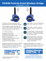
Connector Labeling / Location
The only connections made to the PDWR repeater is
power which is made to a two-position screw terminal
connector as shown in the following diagram. The
connector is located on the rear of display module.
The three empty headers also on the rear of the dis-
play module are not used on the repeater.
Figure 6. PDWR Repeater Display Module Connectors
• Use a flat screwdriver to loosen up the
removable terminal blocks.
Wiring Diagram
Power Connections
Power connections are made to a two-terminal con-
nector labeled POWER in Figure 6.
The PDWR repeater is reverse polarity protected; it
will not be damaged if wired backward.
Make sure that the power supply can provide between
9 and 30 VDC to the wireless device.
Figure 7. Power Connections

PDWR Wireless Signal Repeater
Instruction Manual
13
Setup and Programming
Overview
There are only three items to program on the PDWR
repeater: network ID, password, and encryption.
All programming can be done using PDW Manager
software. In addition, the network ID can be pro-
grammed using the CapTouch through-glass buttons.
After power and input signal connections have been
completed and verified, apply power to the device.
Buttons & Display
Display for PDWR Repeater Unit
Programming Buttons
The units can be programmed using the buttons
located behind the enclosure cover. Use the MENU
button to enter or exit programming mode, the NEXT
button to cycle forward through menu options, the UP
button to cycle backward through menu options, and
the ENTER button to select the menu item or option
you want.
During number entry, use the NEXT button to select a
digit and the UP button to increment the selected
digit.
Button/Symbol
Description
MENU
Enter or exit the device menu
ENTER
Select a menu item of option
UP
Cycle backward through menus or
increment digit
NEXT
Cycle forward through menus or
select next digit
Display
Status
RSSI
Received Signal Strength
Indicator
Indicates the wireless signal
strength between wireless devices
on a scale of 1 to 10. If the repeater
is used in a PDW90 installation, this
value represents the signal strength
between the base station and the
repeater. If the repeater is used in a
PDW30 installation, this value
represents the signal strength
between the primary unit and the
repeater.
RT
Receiving/Transmitting
Flashes while the devices are
sending and/or receiving data
REP
Repeater
Indicates that the device is a
repeater unit. This distinction is
fixed and cannot be changed.

PDWR Wireless Signal Repeater
Instruction Manual
14
CapTouch Buttons
The PDWR repeater is equipped with four capacitive
sensors that operate as through-window buttons.
Their only function is to change the network ID; which
due to through-window buttons, can be changed with-
out removing the cover (and exposing the electronics)
in a harsh operating area.
The first time the CapTouch buttons are used, or after
20 seconds of inactivity, a long finger press for about
two seconds directly over the marked button area of
any button is required to wake up the buttons. After
that, a brief press directly over the marked button
area is all that is required to actuate a button.
When the cover is removed or re-installed, the
CapTouch buttons can be used only after the meter
completes a self-calibrating routine (which can take
up to 20 seconds). Additionally, the sensors are disa-
bled when more than one button is pressed, and they
will automatically re-enable after a few seconds.
CapTouch Button Tips
The CapTouch buttons are designed to work under
any lighting condition and to protect against false trig-
gering.
• Keep the window clean.
• Tighten the cover securely.
• Use a password to prevent tampering.
• The first time the CapTouch buttons are used, or
after 20 seconds of inactivity, a long finger press
directly over the marked button area of any
button of about two seconds is required to wake
up the buttons.
• When the cover is removed or re-installed, the
CapTouch buttons can be used only after the
meter completes a self-calibrating routine (which
can take up to 20 seconds).
• CapTouch buttons will not work if two or more
buttons are detected as being pressed
simultaneously. Be careful to avoid triggering
multiple buttons or reaching across one button
location to press another.
PDW Manager Software
The units can also be programmed using the PC
based PDW Manager. Units connect to a PC via the
micro USB connection on the left side of the display
module, underneath the enclosure cover.
Use of PDW Manager is required for programming
advanced settings, such as wireless encryption.
• Units must be powered externally prior to
programming via USB.
PDW Manager is available for download at
www.predig.com/pdwmanager.
Instructions on the use of PDW Manager to program
the PDWR repeater wireless units can be found under
Programming with PDW Manager on page 16.

PDWR Wireless Signal Repeater
Instruction Manual
15
Setup Menu
The setup menu consists of network ID, password,
and factory defaults restoration.
Entering Numeric Values
Numeric values are set using the NEXT and UP
buttons. Press NEXT to select next digit and UP
to increment digit value.
The selected digit will flash.
Press the ENTER button, at any time, to accept the
value or the MENU button to exit without saving.
Network ID
The network ID determines with which wireless de-
vices the repeater will connect. The repeater unit
must share the same network ID as the other wireless
devices in order to communicate with them.
Password Setup
The wireless repeater may be protected with a four-
digit numeric password in order to prevent unauthor-
ized tampering. When a password has been set, you
will be prompted to enter that password in order to ac-
cess the device menu.
To disable password protection, simply enter 0000 as
the password.
Note: See Entering Numeric Values on page 15 for
instructions on how to enter numbers
Making Changes to a Password
Protected Repeater
Once a password has been set on the device, you will
be required to enter that password before being al-
lowed to access the device menu.
Note: Setting a password will require you to enter the password
to access the device settings via the PC software as well.
Did you forget the password?
The password may be disabled by entering a master
password. If you are authorized to make changes,
enter the master password 7300 to unlock the device.
Restore Defaults
If a mistake has been made while programming the
wireless repeater device, and it is unclear where the
error occurred, the best option may be to perform a
factory reset of the device and begin again.
NOW: 01
NETWORK ID
SET: 01
NETWORK ID
increments selected digit.
selects next digit to the right.
SETUP
PASSWORD
NOW: 0000
PASSWORD (0=OFF)
SETUP MENU
BACK TO
SET: 0123
PASSWORD (0=OFF)
increments selected digit.
selects next digit to the right.
0000 disables the password.

PDWR Wireless Signal Repeater
Instruction Manual
16
Programming with PDW Manager
PDW Manager allows programming of the PDWR wireless repeater unit from a PC with a USB connection. The unit
connects to a PC via the micro-USB connection on the side of the electronics module, underneath the enclosure
cover. Use of PDW Manager is required for programming advanced settings such as wireless encryption.
PDW Manager is available for download at www.predig.com/pdwmanager. Once the software is running, power the
unit using a 9-30 VDC power supply and connect the device to the PC using the provided USB cable.
The PC will automatically install the appropriate device drivers. Once this has completed, the device will appear in the
Device list at the top of the PDW Manager window. Click Connect.
The image below shows the available options on the Configuration tab while the repeater unit is connected.
Note: The two calibration tabs and the I/O Testing tab are not applicable to the repeater unit.

PDWR Wireless Signal Repeater
Instruction Manual
17
Networking Settings and Security
Device communication can be secured by enabling 128-bit AES encryption. A channel mask may also be set for
interference immunity. The encryption key and channel mask may be entered on the Advanced tab.
Once you have entered the encryption information, click Save Settings. The wireless devices must share identical
encryption keys in order to communicate, so be sure to enter the same information for the second unit.

PDWR Wireless Signal Repeater
Instruction Manual
18
Troubleshooting
If you are experiencing difficulties with your wireless installation, consult the troubleshooting steps listed below. For
best results, identify the symptoms of the problem you are having and attempt all the corrective actions listed for the
particular symptom.
Symptom
Possible Cause
Corrective Action
Devices will not connect.
Devices have
mismatched
network IDs.
• Devices will not connect if they do not have the same
network ID. Verify that all devices share the same
network ID.
Devices are out of
range or there are
obstacles blocking
the wireless path.
• Bring devices closer together to see if it alleviates the
issue. Units will display LINK OK if they are
connected. If devices connect, consider placing
closer together permanently, removing any obstacles,
or mounting higher.
• Ensure antennas are on parallel plane. Devices that
are vertically separated will not have as strong of a
connection.
• If communicating over distance of miles, consider
installing additional PDWR repeaters or a high gain
directional antenna.
Multiple wireless
devices in the area
with the same
Modbus ID.
• If there are multiple PDW30 wireless bridges, verify
that each pair has its own unique Modbus ID.
Encryption keys do
not match
• If using encryption, ensure that the encryption keys
on all devices match exactly.
•
Configuration is not
correct.
• Devices must be configured as secondary or
primary units to communicate with each other. Make
sure the display shows PRI on one unit and SEC on
the other unit. The repeater simply extends the
communications distance.

PDWR Wireless Signal Repeater
Instruction Manual
19
Symptom
Possible Cause
Corrective Action
Intermittent signal issues.
Signal is too low.
• Check RSSI. If signal is too low, consider moving
devices closer together, clearing obstacles in
wireless path, or mounting devices higher.
• Ensure devices are on parallel plane.
• If communicating over distance of miles, consider
installing high gain directional antenna.
Temporary
obstacles are
blocking the
wireless path.
• Temporary obstacles, such as large trucks or heavy
equipment, can interfere with wireless path. Consider
moving wireless units higher or to an area with less
traffic.
Devices are
improperly wired.
• Check to make sure all digital inputs and outputs are
properly wired to all devices.
• Check Wiring Diagram starting on page 12.
Device will not power on.
Not enough voltage
is coming from the
power supply.
• Devices require at least 9 VDC each in order to
power on. Check that the power supply is providing
enough voltage to the device and that there are not
too many devices drawing power from the supply.
Devices are
improperly wired.
• Check to make sure all power connections are
properly wired to all devices.
• Check Wiring Diagram starting on page 12.

PDWR Wireless Signal Repeater
Instruction Manual
20
Symptom
Possible Cause
Corrective Action
Device will not connect
to PC via USB.
Wireless device is
not powered.
• The device must be powered by a 9-30 VDC power
supply in order for the PC to recognize it. Power the
wireless device and try again.
Software version is
outdated
• Check that you are running the latest software
version. The latest version of PDW Manager can be
downloaded at www.predig.com/pdwmanager.
USB cable is faulty
• Try connecting the wireless device using a known
good micro USB cable. There are some micro USB
cables that are used for power only and do not
support transferring data.
Device shows “LINK OK”,
but its corresponding pair
shows “LINK LOST”.
A nearby wireless
device has the same
network ID
• The repeater and the primary/secondary pair must
share a unique network ID not being used by other
wireless devices nearby.
Modbus client gets
timeout errors.
The Modbus client
gets timeout errors
trying to read a
Modbus server
connected to the
secondary.
• There are no Modbus settings to be changed in the
repeater.
• Modbus client (master) must be connected to the
primary unit.
• Check all the Modbus settings and make sure they
match the corresponding network.
• Increase the Modbus timeout on the secondary and
the primary, if necessary.
CapTouch buttons
not working.
Device has just been
powered on
• When first powered on, the CapTouch buttons
require a long press to initialize. After the first long
press, you can use them normally.
Lid was removed or
put back on
• After removing or putting the lid back on, the
CapTouch buttons are re-calibrating and will be
inoperable for 20 seconds. After the calibration period
has passed, long press any of the buttons to start
using them again.
CapTouch buttons
have timed out and
are inoperable
• After a 20 second period of inactivity, the CapTouch
buttons will go back to their sleep state. Another long
press is required to wake them up.
/