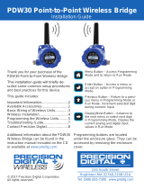
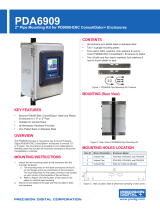
PRECISION DIGITAL PDW30 is a point to point wireless bridge that gives you a simple and straightforward solution to transfer analog, discrete, or Modbus signals even to most remote locations. It is packaged in a rugged and weather-proof housing, designed to meet all the demands of industrial installations. Here are some key features that you will find useful:
Guaranteed ranges: You can be sure that the device will work with your application, or you can send it back - no questions asked.
Wide Input Range: It can take an analog, discrete, or Modbus input and wirelessly broadcasts it to a second PDW30 unit.


-
 1
1
-
 2
2
-
 3
3
-
 4
4
-
 5
5
-
 6
6
-
 7
7
-
 8
8
-
 9
9
-
 10
10
-
 11
11
-
 12
12
-
 13
13
-
 14
14
-
 15
15
-
 16
16
-
 17
17
-
 18
18
-
 19
19
-
 20
20
-
 21
21
-
 22
22
-
 23
23
-
 24
24


PRECISION DIGITAL PDW30 User manual
- Type
- User manual
- This manual is also suitable for
PRECISION DIGITAL PDW30 is a point to point wireless bridge that gives you a simple and straightforward solution to transfer analog, discrete, or Modbus signals even to most remote locations. It is packaged in a rugged and weather-proof housing, designed to meet all the demands of industrial installations. Here are some key features that you will find useful:
Guaranteed ranges: You can be sure that the device will work with your application, or you can send it back - no questions asked.
Wide Input Range: It can take an analog, discrete, or Modbus input and wirelessly broadcasts it to a second PDW30 unit.
Ask a question and I''ll find the answer in the document
Finding information in a document is now easier with AI
Related papers
-
 PRECISION DIGITAL PDW90, PDW90-BA, PDW90-FN User manual
-
 Precision Digital Corporation PDW30-RNA User manual
-
 PRECISION DIGITAL PDW30 Point-to-Point Wireless Bridge Quick start guide
-
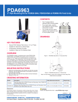 PRECISION DIGITAL PDA6963 User manual
-
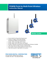
 PRECISION DIGITAL PDW90 Point to Multi-Point Wireless Quick start guide
-
 PRECISION DIGITAL PD6770 User manual
-
 PRECISION DIGITAL PDW30 Point-to-Point Wireless Bridge User manual
-
 PRECISION DIGITAL PDWR User manual
-
 PRECISION DIGITAL PDA6909 User manual
-
 PRECISION DIGITAL PD9000 User manual


Other documents
-
 SloanLED 24/150 Power Supply Installation guide
-
Dwyer Series PDWS User manual
-
Sony PDW-F330K User guide
-
ELPRO 215U-2 User manual
-
ELPRO 450U-E User manual
-
Cooper Elpro 450U-E User manual
-
-
Campbell Scientific CR6 Owner's manual
-
Remote Automation Solutions FloBoss 107 Flow Manager Owner's manual
-
Banner Sure Cross DXM150 Series User manual
