Peerless Industries Projector PJRL411 User manual
- Category
- Projector mounts
- Type
- User manual
This manual is also suitable for

ISSUED: 09-09-02 SHEET #: 054-9122-3 11-11-03
Visit the Peerless Web Site at www.peerlessindustries.com For customer service call 1-800-729-0307 or 708-865-8870.
1 of 5
IMPORTANT! Read entire
instruction sheet before you
start installation and assembly.
WARNING! Installer must verify
that the ceiling will safely
support the combined weight of
the Base Unit, Projector Adapter
Plate, and video projector.
This product contains all mounting hardware for direct attachment to a wood joist
ceiling. Concrete anchors (accessory kit ACC200, see page 2) sold separately.
This product is to be used in combination with one of several Projector Adapter
Plates (PAP models).
To order Projector Adapter Plates, Extension Columns, or additional mounting
hardware call customer service at 1-800-729-0307 or 708-865-8870.
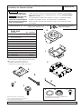
Before you start check the parts list below to make sure all of the parts shown
are included.
Installation and Assembly- Encore™ Projector Mount
Model: PJRL411
*
Four .406 dia. holes provided for threaded rod
installations. Materials and procedure for such
installations are the sole responsibility of the installer.
Peerless Industries, Inc., 1980 Hawthorne Avenue, Melrose Park, IL 60160
www.peerlessindustries.com
Qty.
1
2
9
1
2
1
1
1
3
1
1
Parts List
B
C
F
Note: Actual parts may appear slightly different than illustrated.
J
A
H
G
I
Parts G, H, and I are used only for installations that
incorporate an extension column.
*
K
E
Description
A projector mount ceiling plate
B washer head wood screw
#14 x 2.5 (6mm x 65mm)
C M6 x 1 x 20mm socket head screw
w/ flat and lock washer
D security allen wrench
E M5 x .8 x 8mm socket pin screw
F main bracket assembly
G fiber washer
H retaining collar
I M5 x .8 x 10mm socket pin screw
J roll adapter bracket
K interface bracket
Part Number
054-1003
5S1-015-C03
520-1029
560-9646
520-1062
054-1044
540-9432
1800-375
520-1164
054-1050
055-1251
D
Protected by U.S. Patent No. 6,042,068
© 2003 Peerless Industries, Inc. All rights reserved.
Peerless is a registered trademark of Peerless Industries, Inc.
Encore is a trademark of Peerless Industries, Inc.
All other brand and product names are trademarks or registered trademarks of their respective owners.
R
This product is intended for use with UL
Listed products and must be installed by a
qualified professional installer.

ISSUED: 09-09-02 SHEET #: 054-9122-3 11-11-03
Visit the Peerless Web Site at www.peerlessindustries.com For customer service call 1-800-729-0307 or 708-865-8870.
2 of 5
wood joist
ceiling
A
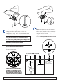
Attachment to a Wood Joist. Use a stud finder to locate
ceiling joist. Drill two 5/32" (4mm) dia. holes 2.5"
(65mm) deep into joist center. Attach projector mount
ceiling plate (A) using #14 x 2.5" (6mm x 65mm) wood
screws (B).
CAUTION: Tighten wood screws so ceiling plate is
firmly attached. But DO NOT TIGHTEN WITH EXCES-
SIVE FORCE! Overtightening can cause stress damage
to wood screws, greatly reducing their holding power!
Tighten to 80 in. lbs. (9 N.M.) maximum torque.
BE SURE TO DRILL INTO JOIST CENTER!
Skip to Step 4
THESE CONCRETE ANCHORS ARE
FOR DIRECT ATTACHMENT TO LOAD
BEARING CONCRETE ONLY! NOT FOR
ATTACHMENT TO CONCRETE CEILING
COVERED WITH PLASTER, DRYWALL,
TILE OR OTHER FINISHING MATERIAL!
USE ONLY RAWL
TM
#5005 OR HILTI
TM
HL814 CONCRETE EXPANSION ANCHORS
[.312 x 1.625 (8mm x 41mm)]. Order
accessory kit #ACC200.
concrete
ceiling
concrete
anchor
CONCRETE ANCHOR INSTALLATION
Concrete
Anchor
A
Attachment to a Concrete Ceiling.
NOTE: Concrete anchors are sold separately.
Order accessory kit #ACC200.
Drill two 5/16" (8mm) dia. holes 1.75" (45mm)
deep. Attach projector mount ceiling plate (A)
using two concrete anchors.
Tighten to 80 in. lbs. (9 N.M.) maximum torque.
See also CONCRETE ANCHOR INSTALLATION
below. Skip to Step 4
CROSS SECTION
A
Tighten to 80 in.
lbs. (9 N.M.)
maximum torque.
∅ 5/32"(4mm)
ceiling
∅ 5/16"(8mm)
B

ISSUED: 09-09-02 SHEET #: 054-9122-3 11-11-03
Visit the Peerless Web Site at www.peerlessindustries.com For customer service call 1-800-729-0307 or 708-865-8870.
3 of 5
G
H
A
ceiling plate
(sold separately)
extension
column (sold
separately)
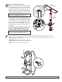
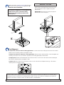
Extension column applications only:
Insert end of extension column into threaded fitting in
ceiling plate. Tighten securely - four or five complete
turns. Align slot in extension column with one of the
small holes in the side of the threaded fitting. Insert
and tighten one M5 x .8 x 10mm socket pin screw ( I )
into hole to lock extension column to threaded fitting.
Tighten screw allen wrench (D).
WARNING: For safety, extension column must be
locked to threaded fitting with screw ( I )!
Attach projector mount ceiling plate (A) with fiber
washer (G) and retaining collar (H). Tighten retaining
collar securely, four or five complete turns, aligning
one hole in the side of retaining collar with slot in the
end of extension column. From inside insert and
tighten one M5 x .8 x 10mm socket pin screw ( I ) into
hole in retaining collar. Tighten screw with allen
wrench (D).
Note: You may need to thread the socket pin screw
from the outside first (approximately 3 turns) to
loosen any buildup that may be on the threads.
WARNING: For safety, retaining collar must be
locked to extension column with screw ( I )!
I
slot
threaded
fitting
J
A
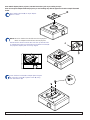
Attach roll adaptor bracket (J) to ceiling plate (A) using four M6 x 1 x 20mm socket head security screws (C).
Tighten using 4mm allen wrench provided. Next attach main bracket (F) using remaining fasteners (C). Tighten
using 4mm allen wrench provided.
IMPORTANT: Do not lose or dispose of allen wrench.
It will be required to attach the Projector Adapter Plate.
NOTE: Arrow indicates front of main bracket (F).
C
I
F

ISSUED: 09-09-02 SHEET #: 054-9122-3 11-11-03
Visit the Peerless Web Site at www.peerlessindustries.com For customer service call 1-800-729-0307 or 708-865-8870.
4 of 5
Place interface bracket (K) on top of adapter
plate as shown.
Fasten interface bracket (K) to adapter plate using two
M5 socket-pin screws (E). Tighten screws (E) using
4mm allen wrench (K).
K
*
#
E
Note: The Projector Adapter Plate and projector you are installing may differ in appearance from the sample illustrated
below.
Note: Attach adapter plate to projector (see PAP instructions) prior to proceeding to step 5
NOTE:
#
Notch on interface bracket indicates front of projector.
*Notch on adapter bracket indicates front of projector.
Rotate interface bracket until the two holes line up with two holes
on adapter plate. Make sure that both front of interface bracket (K)
and projector adapter plate are closely aligned.

ISSUED: 09-09-02 SHEET #: 054-9122-3 11-11-03
Visit the Peerless Web Site at www.peerlessindustries.com For customer service call 1-800-729-0307 or 708-865-8870.
5 of 5
ceiling
(cutaway)
Position four tabs in interface bracket (K) behind four
tabs in base unit. Slide forward to engage latch. BE
SURE THAT LATCH IS ENGAGED!
WARNING:
Do not lift more weight than you can handle! Use
additional man power or mechanical lifting
equipment to safely handle placement of the
video projector!
Lock the latch by tightening M6 x 1 x 20mm socket
head security screw (C) through hole in base unit,
into threaded hole in latch. Tighten using 4mm
allen wrench.
IMPORTANT: Allen wrench is your key for projector
removal. Store it in a safe place.
SECURITY OPTION
Peerless offers several Projector Mounts to fit various video projectors. New Projector Mounts are continually being
developed to meet the demands of a growing projector market. To find out if a mount is available for your particular
projector call Peerless customer service at 1-800-729-0307 or 708-865-8870.
ceiling
(cutaway)
K
latch
C
latch
To adjust Yaw (swivel) for flush mounting applications: Loosen wood screws until projector mount can be rotated.
Rotate mount to desired position and retighten screws.
To adjust Yaw (swivel) for extension column applications: Rotate mount to desired position. Insert and tighten one
remaining socket pin screw ( I ) into tab in projector mount ceiling plate (A) as shown below.
To adjust pitch (forward and backward tilt), loosen the two screws on each side of the main bracket assembly (F).
Tilt mount to desired position and tighten screws.
To adjust roll (side to side tilt), loosen the two screws on each side of the roll adapter bracket (J). Tilt mount to
desired position and tighten screws.
Final Alignment
I
-
 1
1
-
 2
2
-
 3
3
-
 4
4
-
 5
5


Peerless Industries Projector PJRL411 User manual
- Category
- Projector mounts
- Type
- User manual
- This manual is also suitable for
Ask a question and I''ll find the answer in the document
Finding information in a document is now easier with AI
Related papers
-
Peerless Industries ACC 830 User manual
-
Peerless ACC 830 User manual
-
-
-
-
-
-
-
-
Other documents
-
-
-
-
Atdec TH-WH-PJ-FM/TAA Specification
-
Gateway PJ-G210 Installation And Assembly Manual
-
Atdec TH-WH-PJ-FM Datasheet
-
-
-
-