Page is loading ...

Ditec EL500E
www.ditecentrematic.com
IP2358EN • 2020-02-14
Installation manual for digital control unit for 3-phase motors with encoder or mechanical limit
switches
(Translation from original instructions)
Made in Italy

Index
DESCRIPTION 4
DIRECTIVES 4
TECHNICAL DETAILS 5
1. ENCLOSURE INSTALLATION 8
2. ELECTRICAL OPERATING INSTRUCTIONS 8
2.1 CONTROL UNIT POWER SUPPLY 8
2.2 MOTOR POWER SUPPLY 9
3. PUSH BUTTONS 9
3.1 ADDITIONAL CONTROL BUTTONS 9
4. CONTROL UNIT SET-UP 10
4.1 SET-UP MODE ACTIVATION 10
4.2 BASIC PROGRAMMING 10
4.3 RESET PROCEDURE 11
5 OPERATION WITH ENCODER MOTOR 12
5.1 CONNECTING ENCODER LIMIT SWITCHES 12
5.2 CONFIGURATION OF ENCODER LIMIT SWITCH 13
5.3 ENCODER LIMIT SWITCH ADJUSTMENT 14
5.4 FINE-TUNING OF ENCODER LIMIT SWITCH 15
6.
OPERATION WITH MOTOR WITH MECHANICAL LIMIT SWITCHES 16
6.1 CONNECTING MECHANICAL LIMIT SWITCHES 16
6.2 CONFIGURATION FOR MECHANICAL LIMIT SWITCH 17
7. OPERATION MODE 17
8. WORKING TIME SET-UP 18
9. AUTOMATIC CLOSING 18
10. “CAR WASH” FUNCTION 19
11. TEMPORARY DISABLING OF AUTOMATIC CLOSING 19
12. PARTIAL OPENING WITH ENCODER LIMIT SWITCHES 20
12.1 AUTOMATIC CLOSING FROM PARTIAL OPENING 20
13. SAFETY DEVICES 21
13.1 PHOTOCELLS 21
13.2 SAFETY EDGE 22
13.3 SECONDARY MOVABLE SAFETY EDGE 23
13.4 AUX RELÈ MANGEMENT (max 230Vac/5A) 23
14. PARAMETER LIST 24
15. FLASHING LIGHT CONNECTION (230Vac with self-flashing) / COURTESY LIGHT 27
15.1 FLASHING LIGHT 27
15.2 COURTESY LIGHT 27
15.3 ADDITIONAL RADIO RECEIVER MODULE NRGZENX1 (OPTIONAL) 28
15.4 “GO FUNCTION” 28
16 SIGNAL VISUALIZED ON THE DISPLAY 29
17. TROUBLESHOOTING 30
17.1 ERROR CODES - D15 ERROR LED 30
17.2 DISPLAY ERROR CODE 31

3
IP2358EN
This installation manual is intended for qualified personnel only.
Installation, electrical connections and adjustments must be performed in accordan-
ce with Good Working Methods and in compliance with the present standards.
This product must only be used for the specific purpose for which it was designed.
Any other use is to be considered improper and therefore dangerous. The manufac-
turer cannot be held responsible for any damage caused by improper, incorrect or
unreasonable use.
Read the instructions carefully before installing the product. Incorrect installation
may cause danger.
The packaging materials (plastic, polystyrene, etc.) should not be discarded in
the environment or left within reach of children, as they are a potential source
of danger.
Before installing the product, make sure it is in perfect condition.
Do not install the product in explosive areas and atmospheres: the presence of in-
flammable gas or fumes represents a serious safety hazard.
The safety devices (photocells, safety edges, emergency stops, etc.) must be installed
taking into account the applicable laws and directives, Good Working Methods, instal-
lation premises, system operating logic and the forces developed by the automation.
Before connecting the power supply, make sure the plate data correspond to those of
the mains power supply. An omnipolar disconnection switch with a contact opening
distance of at least 3mm must be fitted on the mains supply.
Check that there is an adequate residual current circuit breaker and a suitable over-
current cutout upstream of the electrical installation in accordance with Good Wor-
king Methods and with the laws in force.
When requested, connect the automation to an effective earthing system that com-
plies with current safety standards.
During installation, maintenance and repair operations, cut off the power sup-
ply before opening the cover to access the electrical parts.
The electronic parts must be handled using earthed antistatic conductive arms.
The manufacturer of the motorisation device declines all responsibility if component
parts not compatible with safe and correct operation are fitted.
Only use original spare parts when repairing or replacing products.
GENERAL SAFETY PRECAUTIONS
Failure to observe the information given in this manual may lead to personal
injury or damage to the equipment. Keep these instructions for future reference

4
IP2358EN
DESCRIPTION
Specific use
The control unit is specific for doors moved by a single motor.
Safely operation are guaranteed only with the normal specific use.
Ditec is not responsible for improper use or non-compliance with safety instruction contained in this manual.
No-changes are permetted, otherwise the declaration of conformity will be considered void.
WARNING: it is recommended to activate the impulsive mode only after having completed the set-up and ad-
justments of the control unit. In particular, during the limit switches adjustment select only the deadman
operation mode.
Spare parts
Use only original spare parts.
DIRECTIVES
Entrematic Group AB declares that the Ditec EL500E control panel complies with the fundamental requisites and other
relevant requirements laid down by the following EC directives:
Directives – EMC Directive 2014/30/EU
EN 61000-6-3 (2007) + A1:2011 Emission – Residential
EN 61000-6-1 (2007) Immunity – Residential
EN 61000-6-4 (2007) Emission – Industry
EN 61000-6-2 (2005) Immunity – Industry
EN 61000-4-3 (2006) +A1(2008) +A2(2010) RF-field immunity
EN 60335-1 (2012)/AC:2014 Safety – Part 1: General requirements
Directives – Low Voltage Directive LVD 2014/35/EU
EN 60335-1 (2012)/AC:2014 Safety of Household and similar electrical appliance/ Part 1.
EN335-2-103:2015
Technical documentation of safe integration provided.
TÜV certificate conformity with:
EN 12453 (2017) Industrial, Commercial and garage doors and gates. Safety in use
EN ISO 13849-1:2015 Safety of machinery
The production process is aimed to ensure the compliance of the equipment with the technical documentation and it is
regularly evaluated by an independent certifying body.
Technical dossier manager:
Matteo Fino E-mail: matteo.fino@entrematic.com
Entrematic Group AB
Lodjursgatan 10
SE -261 44 Landskrona
Sweden
Location Date Signature
Landskrona 14-02-2020 Matteo Fino
Ma
M
M
M
M
M
M
M
M
M
M
M
M
M
M
M
M
M
M
M
M
M
M
M
M
M
M
M
M
tt
t
tt
t
t
tt
tt
t
t
t
tt
t
t
t
t
tt
t
t
t
eo
F
F
F
F
F
F
F
F
F
F
in
in
in
in
in
in
in
n
in
in
in
in
in
in
in
in
n
n
i
in
n
i
n
i
in
in
i
in
in
i
o

5
IP2358EN
TECHNICAL DETAILS
Installation Vertical on a flat wall
Temperature range (operating) -10°C / +50°C
Humidity Up to 93% RH non-condensing
Degree of protection IP54
PCB dimension 163x225x80mm
Supply voltage
3x400VAC; 50/60H; ± 10% L1,L2,L3,N,PE
3x230VAC; 50/60H; ± 10% L1,L2,L3,PE
Mains fuse max: 3 x 10A
Rated insulation voltage Ui = 400V
Transformer Max 13 VA , VDE 0570/EN61558
Primary 230VAC winding is thermal protected by built-in thermal transformer fuse.
Both secondary windings are overload protected by multifuses.
Motor output Max motor load by 3x400VAC: 4kW
Max motor load by 3x230VAC: 2.3kW
Max motor current: 8.5A
Emergency stop, Stop, Thermo spec.
door stop and Safety chain Function as normal stop command and disconnect power to contactor coils
24VDC Output (terminals X3-18,X3-19) 24VDC ± 20% (non-regulated), Max load: 250mA
Safety edge input PNE/air switch
Electric type - 8.2KΩ termination ± 10%
Optical type Performance level C, Category 2
Optical safety edge
Input voltage level high (green): 2.5 - 5.0V
Input voltage level low (green): < 0.5V
Input frequency range (green): 250 – 2000Hz (50% duty-cycle)
Pulse interval maximum (green): 7.0ms (when not 50% dutycycle)
Photocell input X3-18, 22 or X12 1, 3 External photocell, 24VDC (e.g. self contain photocell)
Performance level C, Category 2
Electronic limits RS485, Data+ Data-, terminated with 120Ω
Relé (K3+ X17) Contatti Max 230VAC / 5A
Box dimension 210x305x120mm

6
IP2358EN
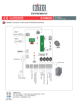
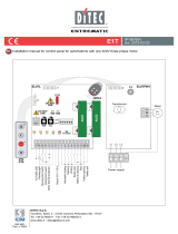
X1 MAIN SUPPLY TERMINAL (L1, L2, L3, N)
X2 PLUG IN CONNECTOR FOR MOTOR (U, V, W)
X3 TERMINALS FOR SAFETY DEVICES
X5 INTEGRATED PUSHBUTTON
X12 PHOTOCELL 1 TERMINALS (PHOTO 1)
X17 TERMINALS FOR AUXILIARY DEVICES - AUX RELAIS MAN-
AGEMENT
P1 PUSH-BUTTON
X7 SLOT MODULO RADIO NRGZENX1
X8
TRAFFIC LIGHT LAMP SLOT NRGFTL - OPTIONAL
X13 TERMINALS FOR ABSOLUTE ENCODER
X16 GROUND TERMINALS
S4 DIP SWITCH FOR PROGRAMMING
X20 SECONDARY MOVABLE SAFETY EDGE
S4
X8
X13
X16
X2
X5
X20
X12
X7
X3
X1
X17
K3
P1

TACHO
+24VDC
PNP
BROWN BROWN
GREEN
GREEN
WHITE
WHITE
t°
1
2
3
4
5
6
7
8
9
10
11
12
13
14
15
16
17
18
19
20
21
22
23
24
25
26
27
4
3
2
1
28
29
30
31
1
2
5
6
X13
X3
X20
1
2
23
24
3
4
1
2
3
5
6
4
18
17
19
1
2
9
10
1
2
3
4
5
6
3
4
15
16
+12V
DATA +
DATA -
PULSE
NPN
12/24V
12/24V
NA / NC
0V
XT
0V
XR
3
4
4
3
2
1
X17
X12
NO
NC
COM
+24V
GND TEST
EMERGENCY
STOP
PUSHBUTTON
BOX
OPEN
STOP
CLOSE
OPEN
LIMIT
CLOSE
LIMIT
GND
“GO FUNCTION”
MECHANICAL
LIMIT SWITCHES
1/2 OPEN
LIMTI SWITCH
TACHO FOR
FORCE CONTROL.
(IF NO TACHO IS
BUILD IN THE E.
ENCODER)
OPTICAL
SAFETY EDGE
THERMO OR
SPECIAL DOOR
STOP
ENCODER FOR
ELECTRONIC LIMITS WITH
BUILD-IN TACHO
PHOTO 1
LIN2/
AXP2/
LAB4
SCREW-
TERMINALS
GND
SAFETY CHAIN
AUX
(max 230V~ / 5A)
OPTIONAL RELAY K3
OUTPUT
SOFA/SOFB
4
3
SOFA/SOFB
LED
RX
JP1
TX
01 01
PHOTO 2
LIN2/
AXP2/
LAB4
FUTURE USE
7
IP2358EN
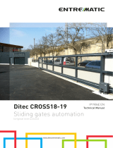
FIG. 1

8
IP2358EN
If you need to disconnect the power cable and then to reconnect it or change the control unit wiring sequence, you
HAVE To connect the wires properly (following the diagram above), restoring the original configuration.
Take care to connect the ground wire to the X16 terminal.
1. ENCLOSURE INSTALLATION
For a correct installation:
• Install where the control unit can be protected from rain or adverse weather conditions.
• Mounting must be vertical.
• The surface has to be checked for flatness, slope and freedom from vibrations.
• Do not install in an area of potential risk of condensation.
• It is important that the door can be clearly seen from the position of the control through its travel.
• Install in an area not accessible to children or unauthorized persons.
• Do not perform any electrical connections before the enclosure installation is completely accomplished.
2. ELECTRICAL OPERATING INSTRUCTIONS
(Read carefully and respect the connection’s sequence).
IMPORTANT! All the connection operations must be performed only after the main power supply has been dis-
connected.
TURN OFF THE MAIN POWER SWITCH BEFORE ANY OTHER OPERATION!
When connecting control to mains supply a mains isolator switch (16A CEE - plug) according EN 12453 is required.
The supply disconnect device (main switch or CEE plug) must be installed between 0.6m and 1.7m above floor level.
2.1 CONTROL UNIT POWER SUPPLY
WARNING! The installation must include an automatic cut off switch with minimum distance between the con-
tacts of at least 3mm.
The control unit can be powered in two different modes: 400V~ 3-phase and 230V~ 3-phase.
The power supply of the motor and of the control unit must correspond.
WARNING: if you connect the wires differently from what is shown in the diagrams you can damage the motor
and the control unit and endanger the safety of the installer.
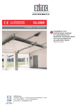
Here below shown the connection diagrams based on the selected power supply:
3x400VAC + N + PE 3x230VAC + PE
L1 L2 L3 N
PE PE
MAIN CEE PLUG
PE PE
X16
X1
BROWN
BLACK
GRAY
BLUE
PE PE
MAIN CEE PLUG
PE PE
WIRE JUMPER
X16
L1 L2 L3 N
X1
BROWN
BLACK
GRAY

9
IP2358EN
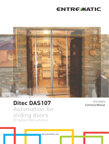
2.2 MOTOR POWER SUPPLY
IMPORTANT! All the connection operations must be performed only after the main power supply has been dis-
connected.
TURN OFF THE MAIN POWER SWITCH BEFORE ANY OTHER OPERATION!
After installation it is possible to connect motor and central unit with
cable Ditec NRGCAB:
• Connect free wires to the X2 terminal (as shown here on the side),
and verify the direction of the motor rotation.
• Link the ground conductor to connector X16.
WARNING!
Verify the direction of rotation of the motor supplied with
400V or 230V 3-phase
:
by pressing the OPEN button (S2) the door
has to open while, by pressing the CLOSE button (S3), the door
must close.
In case of wrong direction, reverse two of the phases (L1, L2 and
L3) on the X1 terminal.
3. PUSH BUTTONS
The keyboard on the cover of the control unit is connected to terminal X5 through the flat cable (A): if you need to dis-
connect the flat and then to reconnect it, pay attention to the direction of connection (reference point B).
3.1 ADDITIONAL CONTROL BUTTONS
B
X5 A
1
2
3
4
5
6
7
8
9
1
0
1
1
1
1
1
1
1
1
1
1
1
1
1
1
1
1
1
1
1
1
1
1
1
1
1
1
1
1
1
1
1
1
1
1
1
1
1
1
1
1
1
1
1
1
1
1
1
1
1
1
2
2
2
2
C
L
OS
E
O
PEN
S
T
O
P
X
3
X
X
To do it:
1. connect a normally closed button, eliminating the standard jumper, to
the contacts 3 and 4 for the STOP command;
2. connect a normally open button to the contacts [5] and [6] for the OPEN
command (S2);
3. connect a normally open button to the contacts [7] and [8] for the CLOSE
command (S3).
PAY ATTENTION AT THE CONNECTIONS! No line voltage (230V~ or
other external devices) can be connected to the buttons otherwise
the unit is damaged.
You can connect additional control
pushbuttons through the terminals
from 3 to 8 of the X3.
UV W
PE PE PE PE
WIRE
JUMPER
NRGCAB
X16
X2
M

10
IP2358EN
D10 - Stop active
(X3:1-2, X3:3-4, X3:28-29, X13:2-5, X2:4-5)
LED is also active in fail mode.
Observe display and D15 ERROR LED
D13 - Open (S2) active
D12 - Close Limit active
D28 - Power ON to Open contactor
D16 - Close (S3) active
D14 - Open Limit active
D29 - Power ON to Close contactor
D15 - Error LED - Shows error codes
LEDs:
4. CONTROL UNIT SET-UP
The set-up must be performed with the motor off. Follow carefully the steps as described in the procedures, DO
NOT activate any safety, hand controls or radio controls unless specifically requested by the procedure.
Basically the set-up of the control and the right coupling control/motor must be performed by the installer.
4.1 SET-UP MODE ACTIVATION
To enter the control unit programming mode place the DIP1 of the switch (S4) in ON.
During set-up the control unit will work only in dead man mode.
To return to the normal operating mode, place the DIP1 of the switch (S4) in OFF.
4.2 BASIC PROGRAMMING
The control unit is supplied with a basic setting performed at the factory which can be restored at any time with the
reset procedure (see paragraph 4.3).
Before beginning the programming procedure:
1. Open the cover of the unit.
2. Make sure all the connections have been made correctly and that the emergency stop or other safety devices are
not activated. Otherwise the display shows the stop symbol active .
3. Find the buttons OPEN (S2) - CLOSE (S3) - STOP (S1) and the 4 switches (S4) on the board.
4. Ensure that the LED D10 is not flashing (in case it flashes, check again point 2).
8k2 OR
PNEU.
EDGE
SAFETY
PHOTO
X3
SAFETY
P
HOTO
P
HOTO 2
2
4 V
OUTPU
T
SPEED INPU
T
1/2 OPEN
L
IMIT SW
.
+24V
OPEN
L
IMIT SW
.
CLO
SE
L
IMIT SW
.
G
O FUNCTIO
N
CLOS
E
OPEN
STO
P
E
MER. STO
P
X3
1
2
ON
D
I
P
3
4
OFF <->ON
OPEN
(
S2
)
S
TOP (S1)
C
LOSE (S3
)
S4
FIG. 4

00:00
01
00:00
02
99
98
00:00
01
00:00
02
99
98
00:00
1 2
5
3 4
FAC
1 2 3
11
IP2358EN
00:00
STOP (S1) button: to switch from PARAMETER field to VALUE field.
OPEN (S2) / CLOSE (S3) buttons: to increase or decrease the size of the fields PARAMETER and VALUE
1. Put DIP switch 1 (S4) in ON position, PARAMETER digits start blinking
2. Select by OPEN (S2) / CLOSE (S3) buttons the number desired
3. Confirm by STOP (S1) button the PARAMETER selected. The VALUE digits start blinking
4. Select by OPEN (S2) / CLOSE (S3) buttons the number desired
5. To confirm the VALUE selected and return to PARAMETER field press STOP (S1) button
6. To leave the set-up mode, place the DIP1 in OFF.
i
NOTE: Some parameters require a further selection after pressing the STOP button (S1) as confirmation of the
desired value. For example, to operate the door during the limit switch set-up the display shows RUN .
The complete list of the parameters and values is available to the paragraph 13.
4.3 RESET PROCEDURE
The reset procedure allows to erase the settled data of the control unit memory and to return to the default program-
ming.
1. Put DIP 4 (S4) to ON position
2. Within 2 seconds press simultaneously the STOP (S1) / OPEN (S2) buttons
3. Display will shows FAC blinking and the control unit software version number
4. Put DIP 4 (S4) to OFF positio:
PARAMETER
digits
VALUE
digits
i
NOTE: when the control unit is power on, the display shows 4 digits about
the firmware version.

12
IP2358EN
1
2
3
4
5
6
1
2
3
4
5
6
7
8
9
10
11
12
13
14
15
16
17
18
19
20
21
22
23
24
25
26
27
28
29
30
31
1
2
3
4
5
6
X3
PUL
S
E IN
REF.
S
WIT
C
H
ENCODER
THERMO
/
SPEC
DOOR STOP
S
AFETY ED
GE
O
PTI
C
AL
8k2 O
R
PNEU.
ED
GE
S
AFETY
PHOT
O
WHITE
GREEN
BROWN
PHOTO
2
24
V
O
UTPUT
SPEED INPUT
1/
2 OPE
N
LIMIT SW
.
+24
V
O
PE
N
LIMIT SW
.
C
L
OS
E
LIMIT
S
W
.
GO
F
U
N
C
TI
ON
C
L
OS
E
OPE
N
STO
P
EMER. STO
P
X13
DATA -
DATA +
GND
+12V
SAFETY CHAIN
123
456
FIG. 5a
FIG. 5
NRGCAB
5 OPERATION WITH ENCODER MOTOR
5.1 CONNECTING ENCODER LIMIT SWITCHES
The control unit is pre-set to the type of encoder limit switch.
The encoder limits switch wires are connected according to the diagram of fig. 5.
ATTENTION: if you connect a control unit pre-set for encoder limit switches to a motor with
mechanical limits, the motor does not perform correctly. In particular, the motor will
not find the limit positions and this could put at risk the safety of people and/or things.
The limit switches connector (1) of the multicore cable (NRGCAB) must be connected to the
male connector (2) of the cable the control unit is provided with (Fig. 5a).
1GREY > GRD
2GREEN > DATA -
3WHITE > GRD
4YELLOW > DATA +
5PINK > SAFETY
6BROWN > +12V
i
NOTE:
in case you are not using a Ditec NRGCAB
cable, you have to use a cable with AMP 0172168
connector at both ends

13
IP2358EN
00:00. 1 1:00 1 1:00 1 1:05
1 1:00
1 2 3 4 5
05
5.2 CONFIGURATION OF ENCODER LIMIT SWITCH
1. Put DIP 1 (S4) in ON position, PARAMETER digits start blinking
2. Select by OPEN (S2) / CLOSE (S3) buttons the number 11
3. Confirm by STOP (S1) button the PARAMETER selected. The VALUE digits start blinking
4. Select by OPEN (S2) / CLOSE (S3) buttons the VALUE:
- VALUE 05: standard installation. Check the rotation direction of the shaft while the door going up (opening) as
shown in fig. 5b
;
- VALUE 06: not standard installation. While the door going up (opening), the rotation direction is opposite com-
pared to the previous case.
5. To confirm the VALUE selected and return to PARAMETER digits press STOP (S1) button
6. To leave the set-up mode, place the DIP1 in OFF..
After selecting the type of digital limit switch with encoder it is necessary to cut off the power supply (by disconnecting
the plug or by turning OFF the main switch) and then to connect it once again in order to allow the communication
between the encoder and the control unit.
WARNING: Please follow the installation requirements of the Ditec motors.
For example, if a motor with encoder is installed in a way which the encoder direction is reversed, it will not run cor-
rectly and may put at risk things and/or people.
Ditec disclaims any responsibility from the consequences of an installation not accomplished according to this policy.
After the selection of the encoder limit switch, it is necessary to proceed with the limit switches adjustment.
door door
FIG. 5b
WARNING: Connecting the motor and pressing the up button ( ) the door must go up, otherwise reverse the
phases (see par. 2.2)

12:00
RUN
1
1
1
3
10
14
00:00 12:00
1 2
6
3 4 5
2 sec
14
IP2358EN
14:00
RUN
1
3
15
12
16
00:00 14:00 14
12
76
3 4 5
2 sec
5.3 ENCODER LIMIT SWITCH ADJUSTMENT
WARNING: Check that motor and control unit are connected.
By following the instructions in section 5.2, select the parameter 11 to the value 05 (or 06). In this case the D15 LED
will flash 2 times until both limit switches are not set.
In case the LED D15 blinks only one time, it is necessary to check the correct connection between encoder and
control unit and that the correct limit switch type selecting procedure has been accomplished as shown in
paragraph 5.2 in-cluding the shutdown of the unit after the selecting step in the case of standard Ditec encoder.
NOTE:
• the PARTIAL OPENING function cannot be activated during programming (parameter 16) - Paragraph 12;
• the additional photocell on the door frame cannot be active during programming (parameter 31);
• When you change the limit switch positions the force control value (parameter 41) and operating time (parameter
51) will be reset to the factory default settings.
UP LIMIT SWITCH ADJUSTMENT
1. Put DIP 1 (S4) in ON position, PARAMETER digits start blinking
2. Using the buttons OPEN (S2) and CLOSE (S3) select the parameter 12
3. Access the field VALUE pressing STOP (S1). The field VALUE shows the flashing symbol
4. Press button STOP (S1) once again and the unit, showing the message RUN , is ready to move the door
5. Use buttons OPEN (S2) and CLOSE (S3) to reach the exact UP limit position
6. Press the STOP button (S1) to confirm the position. The display will show the symbol for 2 seconds and then
the PARAMETER field will start flashing again (showing the number 12).
7. To leave the set-up mode, place the DIP1 in OFF.
DOWN LIMIT SWITCH ADJUSTMENT
1. With the DIP1 of the S4 switch in ON and the PARAMETER field still blinking
2. Select by OPEN (S2) / CLOSE (S3) buttons the parameter 14
3. Access the field VALUE pressing STOP (S1). The field VALUE shows the flashing symbol
4. Press button STOP (S1) once again and the unit, showing the message RUN , is ready to move the door
5. Use buttons OPEN (S2) and CLOSE (S3) to reach the exact DOWN limit position.
6. Press the STOP button (S1) to confirm the position. The display will show the symbol for 2 seconds and then
the PARAMETER field will start flashing again (showing the number 14).
7. To leave the set-up mode, place the DIP1 in OFF.
Once the programming phase is correctly accomplished, the LED D15 stops flashing.
If the LED D15 continues flashings with a sequence of 2 flashes the limit switches are not duly set.
Once the limits are set, to tune only one of the two limit positions go to the single parameter 12 or 14 as previously explained.
If the LED D15 shows a sequence of 4 flashes it means that an incorrect encoder direction of rotation has been entered in
parameter 11. Change the value of parameter 11 by choosing the opposite direction of rotation according to paragraph 5.2.
Once the value changed, start with the limit switch adjustment procedure once again.

4
6
3
7
RUN
12
14
1
1
15
00:00 13:00
1 2
65 7
3 4
13:00
4
6
3
7
RUN
14
16
1
3
17
00:00 15:00
1 2
765
3 4
15:00
15
IP2358EN
5.4 FINE-TUNING OF ENCODER LIMIT SWITCH
UP LIMIT SWITCH POSITION TUNING
1. Put DIP 1 (S4) in ON position, PARAMETER digits start blinking
2. Select parameter 13 using the buttons OPEN (S2) and CLOSE (S3)
3. Access the field VALUE pressing STOP (S1). In the field VALUE symbol flashes.
4. Using the buttons OPEN (S2) and CLOSE (S3) vary the value:
- from 4 to 1: progressively decrease the UP position;
- from 6 to 9: progressively increase the UP position.
The adjustment range is max ± 0.8% of the travel of the door.
If the value in not to be changed you can return to the field PARAMETER pressing the STOP button (S1).
5. After modifying the VALUE press the STOP button (S1) to confirm: the display will show RUN .
6. You can test the varied position of the door by moving it through the buttons OPEN (S2) and CLOSE (S3).
7. Press the STOP button (S1) once again to confirm the tuning and return to the PARAMETER field.
8. To leave the set-up mode, place the DIP1 in OFF.
DOWN LIMIT SWITCH POSITION TUNING
1. Put DIP 1 (S4) in ON position, PARAMETER digits start blinking
2. Select parameter 15 using the buttons OPEN (S2) and CLOSE (S3)
3. Access the field VALUE pressing STOP (S1). In the field VALUE symbol flashes.
4. Using the buttons OPEN (S2) and CLOSE (S3) vary the value:
- from 4 to 1: progressively decreases the DOWN position;
- from 6 to 9: progressively increases the DOWN position.
The adjustment range is max ± 0.8% of the travel of the door.
If the value in not to be changed you can return to the field PARAMETER pressing the STOP button (S1)
5. After modifying the VALUE press the STOP button (S1) to confirm: the display will show RUN .
6. You can test the varied position of the door by moving it through the buttons OPEN (S2) and CLOSE (S3).
7. Press the STOP button (S1) once again to confirm the tuning and return to the PARAMETER field.
8. To leave the set-up mode, place the DIP1 in OFF.

16
IP2358EN
6.
OPERATION WITH MOTOR WITH MECHANICAL LIMIT SWITCHES
6.1 CONNECTING MECHANICAL LIMIT SWITCHES
The wiring is preset for encoder limit switch. To set-up the control unit to mechanical limit switch it’s needed to
modify the wiring as shown below (fig. 6).
The limit switches connector (1) of the multicore cable NRGCAB must
be connected to the male connector (2) of the cable the control unit is
provided with (Fig. 6a).
FIG. 6a
1
2
3
4
5
6
7
8
9
10
11
12
13
14
15
16
17
18
19
20
21
22
23
24
25
26
27
28
29
30
31
1
2
3
4
5
6
X3
P
UL
S
E IN
D
ATA -
D
ATA +
G
N
D
+
12V
REF
.
S
WIT
C
H
ENCODER
SAFETY EDGE
O
PTICAL
8k2 OR
PNEU
.
ED
GE
S
AFET
Y
P
HOT
O
WHITE
G
REEN
B
ROWN
S
AFETY
C
HAIN
P
HOTO 2
24 V
O
UTPUT
S
PEED INPUT
1/
2 OPE
N
L
IMIT SW.
+
24V
GO
FUN
C
TI
ON
S
TO
P
E
MER. STO
P
X13
OPEN
LIMIT SW.
CLOSE
LIMIT SW.
CLOSE
OPEN
THERMO/SPEC
DOOR STOP
1
2
3
4
5
6
1
2
3
4
5
6
NRGCAB
ATTENTION!
Terminals 2 and 5 of
the connector X13
must be bridged
1GREY > OPEN LIMIT SWITCH
2GREEN > OPEN BUTTON
3WHITE > SAFETY
4YELLOW > CLOSE BUTTON
5PINK > CLOSE LIMIT SWITCH
6BROWN > SAFETY
FIG. 6
WARNING: connect a control unit pre-set for mechanical limits to a motor with encoder limits, the motor does
not perform correctly. In particular, the motor will not find the limit positions and this could put at risk the
safety of people and/or things.
i
NOTE:
In case you are not using a Ditec NRGCAB
cable, you have to use a cable with AMP 0172168
connector at both ends

17
IP2358EN
01:
0 1
01
01:03
01:02
01:04
Hold-to-run OPEN
Hold-to-run CLOSE (Put a bridge in X3 between terminal 23-24 when there is no safety device)
Impulsive OPEN
Hold-to-run CLOSE (Put a bridge in X3 between terminal 23-24 when there is no safety device)
Not in use
Impulsive OPEN; Impulsive CLOSE. REQUIRED WITH RADIO MODULE NRGZENX1 - OPTIONAL
6.2 CONFIGURATION FOR MECHANICAL LIMIT SWITCH
1. Check the configuration; the parameter must be setted for the use of mechanical limit switches: 1 1:00.
2. Only take care to check the direction of rotation of the motor:
• by pressing the OPEN button (S2), the door must open;
• by pressing the CLOSE button (S3), the door must close.
Otherwise proceed as described in paragraph 2.2.
3. Check that the motor and the control unit are connected as shown in section 6.1 and that the DIP switch S4 is in
OFF.
If correctly installed all LEDs are off and the display will show the symbol which indicates that the motor is
positioned between the two limit switches.
4. Check that:
• pressing the UP button the motor moves the door upwards (the display shows: );
• pressing DOWN button the motor moves the door downwards (the display shows: ).
UP LIMIT SWITCH ADJUSTMENT
Adjust the UP limit switch cam.
When the UP microswitch is pressed, the display will show the symbol: and the LED D14 will switch on.
DOWN LIMIT SWITCH ADJUSTMENT
Adjust the DOWN limit switch cam.
When the DOWN microswitch is pressed, the display will show the symbol: and the LED D12 will switch on.
The door will move between the two positions set by the limit switches cams according to the operation mode shown
in parameter 01 (see section 7).
WARNING: the standard mode of the control unit is dead-man (parameter 01). During the mechanical limit
switch adjustment use this mode.
Refer to section 7 for the other modes of operation.
7. OPERATION MODE
The control unit is pre-set in dead-man control mode (PARAMETER 01, VALUE 01).
It is possible, however, to define different working modes by modifying the value of PARAMETER 01:
WARNING: it is highly recommended to activate the impulsive mode only after having completed the set-up and
adjustments of the control unit. In particular, during the mechanical limit switches adjustment select always
the dead-man operation mode.
During the encoder limit switches set-up the control unit will only allow the dead-man working mode.

00:00. 51:00 51:00
51:02
51:00
1 32 4 5
5a 6
18
IP2358EN
8. WORKING TIME SET-UP
PARAMETER 51 defines the working time of the door.
WARNING! The default parameter is the
51:02
that is to say a working time of 40 seconds.
To turn off or modify the working time, follow this procedure:
1. Close the door and stop at the DOWN limit position.
2. Put DIP 1 (S4) in ON position, PARAMETER digits start blinking
3. Using the buttons OPEN (S2) and CLOSE (S3) select the parameter 51
4. Access the field VALUE pressing STOP (S1)
5. Using the buttons OPEN (S2) and CLOSE (S3) vary the value:
- VALUE 00: Function inactive.
-VALUE 01: Working time 20 seconds.
-VALUE 02: Working time 40 seconds (default).
-VALUE 03: Activate the self learning function to determine the working time.
CAUTION: In order to use this function the limit switches must be already adjusted.
- VALUE 04: Working time 60 seconds
5a. Select the value 00 / 01 / 02 / 04 > press STOP (S1) to confirm
6a. Place the DIP1 again in OFF to be out of the set-up mode.
By selecting a working time, the control unit verify if the door moving time exceeds the predetermined value: if this
happens the door will stop and the display will shows the error code E:03.
5b. Select value 03
6b. Press STOP (S1) to confirm. The control unit, showing RUN is ready to move the door
7b. Using the OPEN button (S2) move the door from the closed position to the open position without interruptions.
8b. Once the UP limit switch is reached, the door stops, RUN stops flashing and the display will automatically return
to field PARAMETER.
9b. To leave the set-up mode, place the DIP1 in OFF.
5b 6b 9b
51:03 51:03
RUN
7b 8b
9. AUTOMATIC CLOSING
Parameter 32 allows the selection of the door automatic closing after a selectable period of time.
IMPORTANT: parameter 32 is visible and accessible only if parameter 01 has been set in impulsive mode
01:03
.
It will be activated only if on parameter 31 is selected at least one photocell (par. 13.1)
00:00. 32:00 32:00 32:03
32:03
1 2 3 4 5
1. Put DIP 1 (S4) in ON position, PARAMETER digits start blinking
2. Using the buttons OPEN (S2) and CLOSE (S3) select the parameter 32

00:00. 36:00 36:00 36:00
36:00
01
1 2 3 4 5
19
IP2358EN
3. Access the field VALUE pressing STOP (S1)
4. Using the buttons OPEN (S2) and CLOSE (S3) vary the value
- The value 00 in the field VALUE inhibits the automatic closing;
- A value greater than 0, from 1 to 99, indicates the number of seconds to wait before the activation of the automatic
closing:
i
NOTE: From 0 to 99 the change is made every second by using the buttons OPEN and CLOSE.
Over 99 the change is made every 10 seconds and the value will flash quickly: for example, the VALUE 18
corresponds to 180 seconds, the value 19 to 190 seconds ...
If you keep the OPEN button pressed you will get a fast increase of the value.
5. Press STOP (S1) to confirm.
6. To leave the set-up mode, place the DIP1 in OFF.
10. “CAR WASH” FUNCTION
Count down of auto closing time starts, only if photo has been activated more than ”photo active time”. Door shall be
complete closed before start of a new cycle.
To enable the temporary disabling of automatic closing:
1. Put DIP 1 (S4) in ON position, PARAMETER digits start blinking
2. Using the buttons OPEN (S2) and CLOSE (S3) select the parameter 36
3. Access the field VALUE pressing STOP (S1)
4. Using the buttons OPEN (S2) and CLOSE (S3) vary the value:
- VALUE 00: function OFF;
- VALUE 01: function ON.
5. Press STOP (S1) to confirm.
6. To leave the set-up mode, place the DIP1 in OFF.
ATTENTION!
Parameter 36 is visible and selectable only if the automatic closing has been selected in parameter 32.
ATTENTION: parameter 33 is selectable only if in the parameter 31 is selected at least one photocell.
00:00. 33:00 33:00 33:03
33:03
1 2 3 4 5
1. Close the door and stop at the DOWN limit position.
2. Put DIP 1 (S4) in ON position, PARAMETER digits start blinking
3. Using the buttons OPEN (S2) and CLOSE (S3) select the PARAMETER 51
4. Access the field VALUE pressing STOP (S1)
5. Using the buttons OPEN (S2) and CLOSE (S3) vary the value:
-
>00
Photo active time in 0,1 sec. Units (e. g. 15 = 1,5 sec.) - (Adjustable 1 – 30 units – 0,1 sec. to 3,0 sec.)
6. Press STOP (S1) to confirm.
7. To leave the set-up mode, place the DIP1 in OFF.
11. TEMPORARY DISABLING OF AUTOMATIC CLOSING
The function stops the automatic closing if activated.
The countdown on the display shows the value of the pre-set waiting time. To activate the temporary lock, with the door
in its UP limit position, hold the STOP button or the emergency stop button for more than 5 seconds.
To restore the automatic closing press CLOSE button or the closing on “GO Function”.

70%
60%
50%
70%
60%
50%
00:00. 16:00 16:00 16:00
16:00
01
02
07
06
1 2 3 4 5
20
IP2358EN
12. PARTIAL OPENING WITH ENCODER LIMIT SWITCHES
With encoder limit switches type, the partial opening can occur through the use of a selector or of an additional button.
To use this feature, the parameter 16 must be configured with a value >01.
If you are using a selector, this one must be connected to terminals 15 and 16 of X3.
If you open the contact of the selector, the use of the partial opening is inhibited.
If you close the contact of the selector, pressing the UP button, the door stops at the partial opening.
The partial opening can be adjusted by setting the PARAMETER 16 at values from 02 to 07 with a progressive change
of the partial opening from 50% to 75% of the travel.
1. Put DIP 1 (S4) in ON position, PARAMETER digits start blinking
2. Using the buttons OPEN (S2) and CLOSE (S3) select the parameter 16
3. Access the field VALUE pressing STOP (S1)
4. Using the buttons OPEN (S2) and CLOSE (S3) vary the value:
- VALUE 02: Partial opening at 50% of the travel
- VALUE 03: Partial opening at 55% of the travel
- VALUE 04: Partial opening at 60% of the travel
- VALUE 05: Partial opening at 65% of the travel
- VALUE 06: Partial opening at 70% of the travel
- VALUE 07: Partial opening at 75% of the travel
5. Press STOP (S1) to confirm
If you are using an additional button, this one must be connected to terminals 15 and 16 of X3.
In this case the UP button allows the opening of the door up to the UP limit position.
While, to move the door to the partial opening you have to press the additional button.
The partial opening can be determined by setting the PARAMETER 16 with values from 08 to 13 with a progressive
change of the partial opening from 50% to 75% of the travel:
- VALUE 08: Partial opening at 50% of the travel
- VALUE 09: Partial opening at 55% of the travel
- VALUE 10: Partial opening at 60% of the travel
- VALUE 11: Partial opening at 65% of the travel
- VALUE 12: Partial opening at 70% of the travel
- VALUE 13: Partial opening at 75% of the travel
12.1 AUTOMATIC CLOSING FROM PARTIAL OPENING
You can set the automatic closing even from the partial opening setting the PARAMETER 17.
1. Activate the automatic closing function (chapter 9).
2. Set the PARAMETER 17:
- VALUE 00: Automatic closing (from partial opening) OFF.
- VALUE 01: Automatic closing (from partial opening) ON.
/