Page is loading ...

Manuale di assemblaggio
per porte scorrevoli.
Assembly handbook for
sliding doors.
Manuel pour l’assemblage
pour portes coulissantes.
Zusammenbauanleitung
für Schiebtürantrieb.
Manual de ensemblaje
para puertas correderas.
Manual de assemblagem
para portas deslizantes.
KIT REX
IP1837 - rev. 2007-07-17
P
E
D
F
GB
I
DITEC S.p.A.
Via Mons. Banfi, 3 - 21042 Caronno Pertusella (VA) - ITALY
Tel. +39 02 963911 - Fax +39 02 9650314
www.ditec.it - [email protected]

2
KIT REX - IP1837
CODE REF DESCRIZIONE DESCRIPTION DESCRIPTION QT
KREX1V
1
2
3
4
5
6
7
8
9
10
-
-
-
-
-
Componenti fissi 1 anta:
Gruppo comando e trazione
Gruppo rinvio cinghia
Gruppo carrello
Attacco cinghia
Supporto attacco cinghia
Tappo battuta
Fermo battuta
Testata cassonetto
Coperchio fermacavi
Piatto fissaggio componenti
Coppia proiett. ricevitore CelPR
Mascherina carter
Etichetta serie automazione
Etichetta senso ap. anta
Manuale installazione
1-leaf fixed components
Control and traction unit
Transmission unit
Carriage unit
Belt connection
Belt connection support
Rabbet plug
Rabbet stop
Transom case head
Wire clip cover
Component anchorage plate
CelPR projector receiver couple
Casing template
Sticker indicating series aut. system
Sticker indicating op. direction door leaf
Installation manual
Composants fixes 1 battant:
Groupe commande et traction
Groupe renvoi courroie
Groupe chariot
Fixation courroie
Support fixation courroie
Butée chariot
Butée
Extrémités caisson
Couvercle serre-câbles
Platine de fixation composants
Couple projecteur récepteur CelPR
Gabarit carter
Étiquette série automatisme
Étiquette sens ap. battant
Manuel d’installation
1
1
2
1
1
2
2
2
10
2
1
1
1
1
1
KREX1N
1
2
3
4
5
6
7
8
9
10
-
-
-
-
-
Componenti fissi 1 anta:
Gruppo comando e trazione
Gruppo rinvio cinghia
Gruppo carrello
Attacco cinghia
Supporto attacco cinghia
Tappo battuta
Fermo battuta
Testata cassonetto
Coperchio fermacavi
Piatto fissaggio componenti
Coppia proiett. ricevitore CelPR
Mascherina carter
Etichetta serie automazione
Etichetta senso ap. anta
Manuale installazione
1-leaf fixed components
Control and traction unit
Transmission unit
Carriage unit
Belt connection
Belt connection support
Rabbet plug
Rabbet stop
Transom case head
Wire clip cover
Component anchorage plate
CelPR projector receiver couple
Casing template
Sticker indicating series aut. system
Sticker indicating op. direction door leaf
Installation manual
Composants fixes 1 battant:
Groupe commande et traction
Groupe renvoi courroie
Groupe chariot
Fixation courroie
Support fixation courroie
Butée chariot
Butée
Extrémités caisson
Couvercle serre-câbles
Platine de fixation composants
Couple projecteur récepteur CelPR
Gabarit carter
Étiquette série automatisme
Étiquette sens ap. battant
Manuel d’installation
1
1
2
1
1
2
2
2
10
2
1
1
1
1
1
KREXGC1
11
12
13
Gruppo carrelli 2. anta REX
Gruppo carrello
Attacco cinghia
Supporto attacco cinghia
Carriage unit for 2nd REX leaf
Carriage unit
Belt connection
Belt connection support
Groupe chariot 2 battant REX
Groupe chariot
Fixation courroie
Support fixation courroie
2
1
1
KREXCS
14
Carrello supplementare >1600
Gruppo carrello
Supplementary carriage >1600
Carriage unit
Chariot supplémentaires >1600
Groupe chariot 1
REXAL
REXAC
REXAIC
REXA30
REXA35F
0KP851B
0KL050A
K5739610R
0K55886
K6107610
0K69543913SPN
VR745N33
VR745N44
VR745N66
KREXSI
V1900N33
V1900N44
V1900N66
V1900G33
V1900G44
V1900G66
15
16
-
-
-
17
18
19
20
21
22
23
23
23
24
25
25
25
25
25
25
Cassonetto e carter
Coppia attacco lungo PAM35
Coppia attacco corto PAM16
Coppia attacchi P833
Coppia attacchi REX anta PAM30
Coppia attacchi PAM35F
Guarnizione cassonetto/carter
Cinghia di trasmissione
Kit viti T.E. M6x10 zincate + rondella
Kit dadi M6 normali zincate
Kit viti T.C. M6x10 zincate
Kit autof. 3,9x13 s.p. nere
Profilo cassonetto naturale
Profilo cassonetto naturale
Profilo cassonetto naturale
Supporto intermedio carter
Profilo carter naturale
Profilo carter naturale
Profilo carter naturale
Profilo carter grezzo
Profilo carter grezzo
Profilo carter grezzo
Transom box protective casing
Pair of long coupling PAM35
Pair of short coupling PAM16
Pair of P833 coupling
Pair of REX couplings PAM30 wing
Pair of REX couplings PAM35F wing
Seal transom box/protective casing
Drive belt
T.E. M6x10 galvan. screws + washer kit
M6 normal galvanized nuts kit
T.C. M6x10 galvanized screws kit
3.9x13 s.p. black self-tapping screws kit
Natural transom box profile
Natural transom box profile
Natural transom box profile
Intermed. protective casing support
Natural protective casing profile
Natural protective casing profile
Natural protective casing profile
Rough protective casing profile
Rough protective casing profile
Rough protective casing profile
Caisson et carter
Paire de fixation longues PAM35
Paire de fixation courtes PAM16
Paire de fixation P833
Couple attaches REX volet PAM30
Couple attaches REX volet PAM35F
Joint caisse/carter
Courroie de transmission
Jeu vis T.E. M6 x 10 galvan. + rondelle
Jeu d’écrous M6 normaux galvanisés
Jeu de vis T.C. M6 x 10 galvanisées
Jeu vis autotaraudeuses 3,9 x 13 S.P. noires
Profil caisson naturel
Profil caisson naturel
Profil caisson naturel
Support intermédiaire carter
Profil carter naturel
Profil carter naturel
Profil carter naturel
Profil carter brut
Profil carter brut
Profil carter brut
1
1
1
1
1
200 m
50 m
1000
1000
1000
1000
3.3 m
4.4 m
6.6 m
1
3.3 m
4.4 m
6.6 m
3.3 m
4.4 m
6.6 m
V2995G30
V2995G60
V2995N30
V2995N60
K3016
K1356N30
K1356N60
K1356G30
K1356G60
KAC
26
26
26
26
27
27
27
27
-
Attacchi anta intelaiata
Profilo attacco anta generica grezzo
Profilo attacco anta generica grezzo
Profilo attacco anta generica naturale
Profilo attacco anta generica naturale
Coppia piatto fiss. anta generica
Attacchi anta in cristallo
Attacco anta in cristallo naturale
Attacco anta in cristallo naturale
Attacco anta in cristallo grezzo
Attacco anta in cristallo grezzo
Kit accessori per AC1356
Framed door wing attachment
Rough gen. door attachment edge
Rough gen. door attachment edge
Natural gen. door attachment edge
Natural gen. door attachment edge
Pair of fixing plates for generic door wing
Glass wing attachment
Natural glass door attachment
Natural glass door attachment
Rought glass door attachment
Rought glass door attachment
AC1356 accessories
Fixation du vantail sur châssis
Profil brut fixation du vantail générique
Profil brut fixation du vantail générique
Profil naturel fixation du vantail générique
Profil naturel fixation du vantail générique
Deux plats fixation vantail générique
Fixation battant a verre
Fixation battant en verre naturel
Fixation battant en verre naturel
Fixation battant en verre brut
Fixation battant en verre brut
Accessoire AC1356
3 m
6 m
3 m
6 m
1
3 m
6 m
3 m
6 m
1
0KP515AB
0KP369
28
29
Pattini guida anta a pavimento
Pattino guida anta intelaiata
Pattino guida anta in cristallo
Floor sliding guide
Sliding guide for framed wing
Sliding guide for glass wing
Rails battant
Rail battant à châssis
Rail battant en verre
10
10
94
192C

3
KIT REX - IP1837
CODE REF DESCRIZIONE DESCRIPTION DESCRIPTION QT
0KZ18REX
LOKSBM
REXAB
30
-
32
Accessori
Blocco di sicurezza
Sblocco supplementare
Antipanico a batterie
Accessories
Safety lock
Supplementary release device
Antipanic with battery
Accessoires
Blocage de sécurité avec déblocage
Déblocage supplémentaire
Antipanique à batterie
-
-
1
VSP14V25 31
Spazzolini
Spazzolini di tenuta
Brushes
Sealing brushes
Brosses
Brosse d’étanchéité 2.5 m
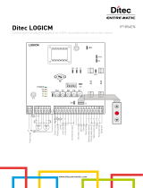
LEGENDA
PL = Vano passaggio orizzontale
LM = Lunghezza anta mobile
LT = Lunghezza totale automazione
LB = Lunghezza cinghia
S = Sormonto (nominale = 50)
CAPTION
PL = Horizontal passageway
LM = Mobile wing lenght
LT = Overall automatic system lenght
LB = Belt lenght
S = Overlap (nominal = 50)
LÉGENDE
PL = Zone de passage horizontal.
LM = Longuer du vantail mobile.
LT = Longuer totale automatisme.
LB = Longuer de la courroie.
S = Chevauchement (nominal=50)
NOTE
(1) Trasformatore esterno
(2) Batterie esterne [32]
(3) Se LM>1600 aggiungere terzo
carrello [14]
(4) Se LT≥3200 usare supporto inter-
medio carter KREXSI [24]
NOTE
(1) External transformer.
(2) External batteries [32].
(3) If LM>1600 add third carriage [14]
(4) If LT≥3200 use the KREXSI
intermediate protective casing sup-
port [24]
NOTE
(1) Transformateur externe.
(2) Batterie externes [32].
(3) Si LM>1600 ajouter un troisiéme
chariot [14]
(4) Si LT≥3200 utiliser support inter-
médiaire du carter KREXSI [24]

6
KIT REX - IP1837
15
31
26
3
23
25
4
5
17
3
23
16
27
31
25
4
5
17
REX
LT - 11
LT - 10
57
100
30
Ø 16
Ø 7Ø 7
10 10
106
23
25
22
x6
20
x2
x10
21
x2
2
23
8
9
30
24
25
1
8
10
19
x2
x4
7
7
32
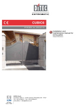
Fig. 1

7
KIT REX - IP1837
REX-2
Gruppo carrello con attacco anta intelaiata - Carriage unit with framed wing attachment - Groupe
chariot avec fixation vantail sur châssis - Laufwagengruppe mit Anschluß für Rahmenflügel - Gru
-
po carro con fijación hoja en el marco - Grupo carro com engate portinhola encaixilhada
PL
LM LM
LT
10 10
S S
OPEN OPEN
OPEN OPEN
15
15
15
15
3
6
19
19
19
18
12
13
4
5
3
18

8
KIT REX - IP1837
REX-2
2
8
LB
30 3232
1 8
7
LT
A
B
C1
C2
7
LM
90 90
LM
90 90
3
15
6
4
5
4
6
5
Code PL LM LT A B C1 C2 LB Note
02REX20
02REX22
02REX24
02REX26
02REX28
02REX30
02REX32
02REX36
02REX40
02REX44
02REX48
02REX52
02REX56
02REX60
02REX66
940
1040
1140
1240
1340
1440
1540
1740
1940
2140
2340
2540
2740
2940
3240
520
570
620
670
720
770
820
920
1020
1120
1220
1320
1420
1520
1670
2000
2200
2400
2600
2800
3000
3200
3600
4000
4400
4800
5200
5600
6000
6600
260
310
360
410
460
510
560
660
760
860
960
1060
1160
1260
1410
100
150
200
250
300
350
400
500
600
700
800
900
1000
1100
1250
-
-
-
-
-
-
-
-
50
50
50
50
50
50
50
250
300
350
400
450
500
550
650
-
-
-
-
-
-
-
2980
3180
3380
3580
3780
3980
4180
4580
4980
5380
5780
6180
6580
6980
7580
(4)
(4)
(4)
(4)
(4)
(4)
(4)
(4)
(3)(4)
A=LM-260
B=LM-420
B≥100
LT=PL+2LM+20
LM=(LT+2S-20)/4
LM=PL/2+S
PL=(LT-2S-20)/2
C2=LT/2-B-650
LB=2(LT-A-B-140)

9
KIT REX - IP1837
REX-1 DX
Gruppo carrello con attacco anta cristallo - Carriage unit with crystal wing attachment - Groupe cha-
riot avec fixation vantail verre - Laufwagengruppe mit Anschluß für Ganzglasflügel - Grupo carro con
fijación hoja cristal - Grupo carro com engate portinhola em cristal
LM
PLS S
LT
10 10
OPEN
OPEN
x6
3
18
5
4
19
3
27
27
16
x2
x2
x6
6
14
19
3
18
5
4
19
3
19
16
16
16
16
6
x2
19

10
KIT REX - IP1837
REX-1 DX
2
30
LB
8
7
8
7
B
A
LT
E
D
1
10
3
6
16
6
6
4
5
5
120
120
LM
LM
16 6
3
3
4
120
120
OPEN
OPEN
Code PL LM LT A B D E LB Note
01REX14
01REX16
01REX18
01REX20
01REX22
01REX24
01REX26
01REX28
01REX30
01REX32
01REX36
01REX40
01REX44
01REX48
01REX52
01REX56
01REX60
01REX66
615
715
815
915
1015
1115
1215
1315
1415
1515
1715
1915
2115
2315
2515
2715
2915
3215
715
815
915
1015
1115
1215
1315
1415
1515
1615
1815
2015
2215
2415
2615
2815
3015
3315
1400
1600
1800
2000
2200
2400
2600
2800
3000
3200
3600
4000
4400
4800
5200
5600
6000
6600
30
30
30
30
30
30
30
30
30
650
750
850
950
1050
1150
1250
1350
1500
0
100
200
300
400
500
600
700
800
350
450
550
650
750
850
950
1050
1200
835
935
1035
1135
1235
1335
1435
1535
1635
1735
1935
2135
2335
2535
2735
2935
3135
3435
200
200
200
200
200
200
200
200
200
50
50
50
50
50
50
50
50
50
2440
2640
2840
3040
3240
3440
3640
3840
4040
4100
4500
4900
5300
5700
6100
6500
6900
7500
(1)(2)
(3)(4)
(3)(4)
(3)(4)
(3)(4)
(3)(4)
(3)(4)
(3)(4)
(3)(4)
(3)(4)
PL=(LT-3S-20)/2
LM=(LT+S-20)/2 LM=PL+2S
LT=PL+LM+S+20
A=LM/2-160
B=LM/2-458
B=LM-715 B≥100
D=LT/2+135
LB=2(LT-A-B-150)

11
KIT REX - IP1837
REX-1 SX
Gruppo carrello con attacco anta cristallo - Carriage unit with crystal wing attachment - Groupe cha-
riot avec fixation vantail verre - Laufwagengruppe mit Anschluß für Ganzglasflügel - Grupo carro con
fijación hoja cristal - Grupo carro com engate portinhola em cristal
LM
PLS S
LT
10 10
OPEN
OPEN
6
x2
x2
x2
6
14
19
3
18
5
4
3
3
18
5
4
19
3
16
16
16
16
27
27
x6
x6
19
16

12
KIT REX - IP1837
REX-1 SX
2
30
LB
8
7
1
8
7
10
B
A
LT
5
32
E
OPEN
OPEN
3
6
16
6
6
4
5
5
120
120
LM
LM
3
3
4
120
120
16
6
Code PL LM LT A B D E LB Note
01REX12
01REX14
01REX16
01REX18
01REX20
01REX22
01REX24
01REX26
01REX28
01REX30
01REX32
01REX36
01REX40
01REX44
01REX48
01REX52
01REX56
01REX60
01REX66
515
615
715
815
915
1015
1115
1215
1315
1415
1515
1715
1915
2115
2315
2515
2715
2915
3215
615
715
815
915
1015
1115
1215
1315
1415
1515
1615
1815
2015
2215
2415
2615
2815
3015
3315
1200
1400
1600
1800
2000
2200
2400
2600
2800
3000
3200
3600
4000
4400
4800
5200
5600
6000
6600
30
30
30
30
30
30
30
30
30
30
650
750
850
950
1050
1150
1250
1350
1500
100
200
250
350
450
550
650
750
850
950
350
450
550
650
750
850
950
1050
1200
5
5
5
5
5
5
5
5
5
5
5
5
5
5
5
5
5
5
5
-
-
50
50
50
50
50
50
50
50
50
50
50
50
50
50
50
50
50
1840
2040
2340
2540
2740
2940
3140
3340
3540
3740
4100
4500
4900
5300
5700
6100
6500
6900
7500
(1)(2)
(2)
(3)(4)
(3)(4)
(3)(4)
(3)(4)
(3)(4)
(3)(4)
(3)(4)
(3)(4)
(3)(4)

13
KIT REX - IP1837
32
23
3
23
9
17
5
4
19
15
19
25
1
19
10
23
30
16
KREX1N
MOT
BL
OPEN
RP
DIP
R1
RESET
27
9
8
3
2
1
1
0
TC
on
off
3 41 2
POWER
ALARM
+
-
+
-
~
~
24 V
BAT
ENC
-
-
+
+
Motor
L
N
230 V~
Transf.
Fuse F1
A
Lock
Fuse
F10A
192C
1CELA
12 V
12 V
P1 SP P2 R1 SR R2
1
2
Rosso - Red
Bianco - White
10
+ -
COM
N.O.
N.C.
24 V= / 0,3 A (max)
Chiusura automatica / Automatic closure; Chiude / Closing
Apre / Openin
g
Sicurezza di inversione / Reversal safety contact
Sto
p
Apertura parziale / Partial openin
g
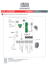
Fig. 2

14
KIT REX - IP1837
Uscita / Output 24 V= / 0,5 A
Reset
Esclusione blocco / Lock exclusion
Comune parziale / Partial common
Stop
Sicurezza in chiusura / Closing safety
Sicurezza in apertura / Opening safety
Chiusura / Closing
Apertura lato B / Opening side B
Apertura lato A / Opening side A
Chiusura automatica / Automatic closure
+
-
MOT
BL
COM
R1
DIP
TC
on
off
POWER
ALARM
SA
IN
DIR
+
-
+
-
~
~
24 V
BA
T
EN
C
-
-
+
+
Motor
L
N
230 V~
Transf.
F1
Lock
Fuse
F10A
EL16
J
SAFETY
ENABLE
COM
OPEN
1 A B
21 22
R
E
M
O
T
E
DIR
0CEL1S
LAN4S
LAN7S
LAB9
BIXLR22
TELRS
COME
TELR
COME
TELR
Converter
DMCS
DIR
PASM24
COMH-K
DIP
RF VA VC RP
COME
TELR
J
12 V
12 V
1 2
272829 0
1
2
3A3B
4
6
8
9
OPEN
1 G141
10 21 22
on
1 2 3
KREX1V
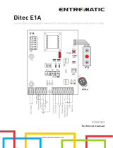
Fig. 3

18
KIT REX - IP1837
GB
GENERAL SAFETY PRECAUTIONS
This assembling manual is intended for professionally
competent personnel only.
The assembling, the electrical connections and the settings
must be completed in conformity with good workmanship and
with the laws in force. Read the instructions carefully before
beginning assembling the product. Incorrect assembling may
be a source of danger.
Packaging materials (plastics, polystyrene, etc) must not be al
-
lowed to litter the environment and must be kept out of the reach
of children for whom they may be a source of danger.
Before beginning the assembling check that the product is in
perfect condition.
Before connecting to the mains check that the rating is
correct for the destination power requirements.
A multipolar isolation switch with minimum contact gaps of 3 mm
must be included in the mains supply. Check that upstream of
the electrical installation there is an adequate differential switch
and a suitable circuit breaker.
For repairs or replacements of products only original spare parts
must be used.
It is recommended that antistatic conductive earthed arm
bands be worn when manipulating electronic parts.
1. ASSEMBLING THE AUTOMATIC SYSTEM
1.1 Assembling procedure
- On the basis of the type of automatic system chosen,
use the sizing table (or the formulas shown) to obtain the
measurements required for the assembly of the automatic
system.
- Cut the aluminium of the transom box LT-10 mm and drill
a hole as shown in fig. 1.
1.3 Cut the aluminium of the protective casing LT-11 mm and
drill a hole as shown in fig. 1.
Note: clean the aluminium in order to remove any traces of cut
material, and clean the carriage sliding tracks in particular.
- Mark measurements A, B and C shown in the table (or
calculated using the formula) on the transom box with a
pencil.
- Insert 2 carriages for each leaf in the guide track; if
LM>1600 add another carriage per leaf (note 1).
- Make the carriages slide along the guide tracks in order to
check that the wheels are not dented (and replace them if
dented).
- Fasten the leaf connection brackets on the carriages (as
shown in the diagrams) and fasten the belt connection and
collision locking brackets to the carriages in the positions
shown in the table.
- Fit the component anchorage plates [10] in the appropriate
guide track of the transom box, see page 11.
- Secure the parts (without over-tightening): command and
drive unit [1], belt transmission [2], block [30] and batteries
[32], to the casing with the supplied screws, and follow the
measurements indicated in the table.
Note: with automatic systems LT≥3200 anchor the protective
casing support bracket [24].
- Position the rabbet stops [7] and rabbet plugs [6] inside
the guide track.
1.2 Adjusting the belt
- Loosen the screws that fasten the transmission unit to the
transom box.
- Loosen the belt connection bracket.
- Cut the belt to measurement LB (see tables), thread the
belt LB between the motor pulley and the transmission unit
[2] and join it in correspondence with the belt connection
bracket (Note: cut off any excess length).
- Pull the entire transmission unit manually to the left and
anchor it to the transom box.
- Loosen the screw until the spring is compressed to 20÷22
mm.
- Lock in place with the screws [F].
- Insert the rabbet stop in the centre of the transom
box without tightening the screws. Keep the carriages
resting against the rabbet stop and fasten the belt on the
carriage.
Attention: a wrong adjustment can prevent the automation from
working properly.
- Tighten all the screws.
- Anchor the heads to the transom box.
2. WIRING
- Connect the command and drive unit [1] to the block [30]
and to the batteries [32] with the appropriate wires.
- For the 192C electronic board version only, connect the
1CELA photocell amplifier to the electronic board (fig. 2).
- Fasten the wires using the wire clips [9] supplied.
2
F
LT<2600 = 22 mm
LT
≥2600 = 20 mm

19
KIT REX - IP1837
GB
3. TESTING THE AUTOMATIC SYSTEM WITH 192C ELECTRONIC BOARD
3.1 Checking the dip-switches
3.2 Functional test
Wire up as shown in fig. 2, close the contacts 1-8, 1-9.
Connect the transformer to mains (230 V~/50 Hz).
Give the following commands to the electric board and visually check for correct response and straight and smooth running.
3.3 Chaos test
Send repeated open and close commands so as to cause the wing or wings to continuously reverse direction of movement without
stopping (for at least 1 minute). Check that the automation system does not fail to appropriately keep wing position under control
nor cause the wing or wings to slam, and that no logic malfunction occurs.
3.4 Checking the trimmers
3.5 Default setting
At the end of the test, make the following settings:
- all the trimmers set to minimum;
- all the dip-switches in the OFF position (the position of DIP2 depends on the type of automatic system);
- disconnect batteries (if installed), checking that the electric board is not being powered by them (press RESET command).
3.6 General controls
- Control the length of the casing, the passage width and the width of the leaf.
- Tie the power supply cable and command cables with related channels.
- Apply the casing seal.
- Perform a general check (belt tension, screw tightness, etc).
- Fill-in and apply the CE label.
ACTION OUTCOME
Electronic board turned on - green LED lit
- red amplifier card LED lit
Command 1-2 permanent and TC trimmer at minimum
- closure manoeuvre
Command 1-3 (impulsive) - opening manoeuvre
Command 27-3 (impulsive) and RP trimmer at minimum
- partial opening manoeuvre
Command 1-8 during closure (contact open) - re-opening
Control of the photocell card during the closure phase:
- connect the 1CelA photocell amplifier to the electronic board
- connect the CelPR
- the gate should open when the optical alignment between TX
and RX is broken.
Command 1-9 (contact open) - stop for the duration of the command
RESET pushbutton (of the electrical control panel)
- reset, encoder zero setting
ACTION OUTCOME
DIP1 = OFF - lock not powered with closed door
- a command powers the lock throughout the opening manoe
-
uvre
Warning: DIP1 must be set to OFF.
DIP2 = OFF for REX2 and REX1-DX
DIP2 = ON for REX1-SX
- variation of the opening direction
DIP3 = ON - battery function, if present, in the event of blackout
DIP3 = OFF - in the event of blackout, the automation with the batteries pre-
sent performs the last opening manoeuvre and then switches
off
ACTION OUTCOME
RP
trimmer adjustment - variation of the partial opening
TC trimmer adjustment - variation of the automatic closure time
R1 trimmer adjustment and opposition to the movement of the
door leaves
- variation of motor power / obstacle detection (reopening and
stopping)

20
KIT REX - IP1837
GB
4. TESTING THE AUTOMATIC SYSTEM WITH EL16 ELECTRONIC BOARD
4.1 Checking the dip-switches
4.2 Functional test
Wire up as shown in fig. 3, close the contacts 41-6, 41-8, 1-9.
Connect the transformer to mains (230 V~/50 Hz).
Give the following commands to the electric board and visually check for correct response and straight and smooth running.
ACTION OUTCOME
Electric board turned on
- green LED lit
Command 1-3A and OPEN button (impulsive)
- closure manoeuvre
Command 1-4 (impulsive)
- opening manoeuvre
Command 27-3B (impulsive) and RP trimmer at minimum
- partial opening manoeuvre
Close contacts 1-2
- re-opening
Command 41-6 during opening (opening contact) - reduce in the last 500 mm of the door stroke when the con
-
tact is opened.
Command 41-8 during closure (contact open) - the gate should open when the optical alignment between TX
and RX is broken.
Control of the photocell card during the closure phase:
- connect the CelPR
- stop for the duration of the command
Command 1-9 (contact open)
- reset, encoder zero setting
Command 1-29 and RESET button (impulsive) - reset, encoder data reset
4.3 Chaos test
Send repeated open and close commands so as to cause the wing or wings to continuously reverse direction of movement without
stopping (for at least 1 minute). Check that the automation system does not fail to appropriately keep wing position under control
nor cause the wing or wings to slam, and that no logic malfunction occurs.
4.4 Checking the trimmers
4.5 Default setting
Set the following configurations at the end of the test:
- all trimmers at minimum;
- DIP1 is dependent on the type of automation; DIP2=ON;
- all DIR dip-switches in the OFF position;
- disconnect batteries (if installed), checking that the electric board is not being powered by them (press RESET command).
4.6 General controls
- Control the length of the casing, the passage width and the width of the leaf.
- Tie the power supply cable and command cables with related channels.
- Apply the casing seal.
- Perform a general check (belt tension, screw tightness, etc).
- Fill-in and apply the CE label.
ACTION OUTCOME
DIP1 = OFF for REX2 and REX1-DX
DIP1 = ON for REX1-SX
- changing the opening direction
DIP2 = ON for REX - automation type selection
Warning: DIP2 must be set to ON
DIP1 = ON - battery function, if present, in the event of blackout
DIP2 = OFF - in the event of blackout, the automation with the batteries pre-
sent performs the last opening manoeuvre and then switches
off
DIP3 = OFF for REX - block type selection
Warning: DIP3 must be set to OFF
DIR
ACTION OUTCOME
TC trimmer adjustment - variation of the automatic closure time
R1 trimmer adjustment - variation of the force on obstacles
RF trimmer adjustment - variation of the motor power
VA
trimmer adjustment - variation of the opening speed
VC trimmer adjustment - variation of the closing speed
RP
trimmer adjustment - variation of the partial opening
/