Page is loading ...

IJ7D:7H:CEJEH?I7J?ED
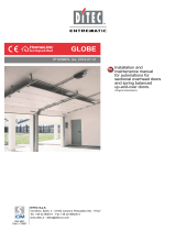
<ZVgbdidg
8dcigdaWdVgY
EdlZgWdVgY
IgVch[dgbZg
&
'
(
)
*
FORYOU
WEOPEN
THEDOORS
Includes:
Silver Grey Cover
On/Off Rocker Switch
Push Or Pull Arm
Max Door Leaf Weight 70 kg
AdlZcZg\ndg[jaanVjidbVi^X
Ejh]VcY\d[VX^a^in
Dc$D[[Id\\aZhl^iX]
-
.
&%
&&
&(
ADSF DITEC SPRINT SWING OPERATOR
Max Door Leaf Weight 80 kg
Motor Open Motor Close
Battery Back Up
INSTALLATION
MANUAL

2
SPRINT - IP1546
Fig. 1
Fig. 2

3SPRINT - IP1546
GB
GENERAL SAFETY PRECAUTIONS
This installation manual is intended for professionally
competent personnel only.
Installation, electrical connections and adjustments must be
performed in accordance with Good Working Methods and in
compliance with applicable regulations.
Before installing the product, carefully read the instructions.
Bad installation could be hazardous. The packaging materials
(plastic, polystyrene, etc.) should not be discarded in the envi-
ronment or left within reach of children, as these are a potential
source of hazard.
Before installing the product, make sure it is in perfect condition.
Do not install the product in an explosive environment and atmos-
phere: gas or inflammable fumes are a serious hazard risk.
Before installing the motors, make all structural changes relating
to safety clearances and protection or segregation of all areas
where there is risk of being crushed, cut convoyed, and danger
areas in general.
Make sure the existing structure is up to standard in terms of
strength and stability. The motor manufacturer is not responsible
for failure to use Good Working Methods in building the frames
to be motorised or for any deformation occurring during use.
The safety devices (photocells, safety edges, emergency stops,
etc.) must be installed taking into account: applicable laws and
directives, Good Working Methods, installation premises, sys-
tem operating logic and the forces developed by the motorised
door or gate.
The safety devices must protect any areas where the risk exists
of being crushed, cut convoyed, or where there are any other
risks generated by the motorised door or gate.
Apply hazard area notices required by applicable regulations.
Each installation must clearly show the identification details of
the motorised door or gate.
Before making power connections, make sure the plate
details correspond to those of the power mains. Fit on
the electrical system an omnipolar disconnection switch with a
contact opening gap of at least 3 mm.
Check there is a differential switch and adequate overcurrent
protection upline from the electrical system.
When necessary, connect the motorised door or gate to a reli-
able earth system made in accordance with applicable safety
regulations.
During installation, maintenance and repair, interrupt the power
supply before opening the lid to access the electrical parts.
To handle electronic parts, wear earthed antistatic con-
ductive bracelets. The motor manufacturer declines all
responsibility in the event of component parts being fitted that
are not compatible with the safe a correct operation.
For repairs or replacements of products only original spare parts
must be used.
The installer shall provide all information relating to automatic,
manual and emergency operation of the motorised door or gate,
and provide the user with operating instructions.
MACHINERY DIRECTIVE
Pursuant to Machinery Directive (98/37/EC) the installer who
motorises a door or gate has the same obligations as the ma-
nufacturer of machinery and as such must:
- prepare the technical file which must contain the documents
indicated in Annex V of the Machinery Directive;
(The technical file must be kept and placed at the disposal of
competent national authorities for at least ten years from the
date of manufacture of the motorised door);
- draft the EC declaration of conformity in accordance with
Annex II-A of the Machinery Directive and deliver it to the
customer;
- affix the CE marking on the power operated door in accordance
with point 1.7.3 of Annex I of the Machinery Directive.
For more information consult the “Technical Manual Guidelines”
available on Internet at the following address: www.ditec.it
APPLICATIONS
Service class: 5 (minimum 5 years of working life with 600
cycles a day)
Applications: HEAVY DUTY (For vehicle or pedestrian acces-
ses to institutional complexes with very intense use).
- Performance characteristics are to be understood as referring
to the recommended weight (approx. 2/3 of maximum permis-
sible weight). A reduction in performance is to be expected
when the access is made to operate at the maximum permis-
sible weight.
- Service class, running times, and the number of consecutive
cycles are to be taken as merely indicative having been statisti-
cally determined under average operating conditions, and are
therefore not necessarily applicable to specific conditions of use.
During given time spans product performance characteristics will
be such as not to require any special maintenance.
- The actual performance characteristics of each automatic
access may be affected by independent variables such as
friction, balancing and environmental factors, all of which
may substantially alter the performance characteristics of the
automatic access or curtail its working life or parts thereof
(including the automatic devices themselves).When setting
up, specific local conditions must be duly borne in mind and
the installation adapted accordingly for ensuring maximum
durability and trouble-free operation.
DECLARATION BY THE MANUFACTURER
Directive 98/37/EC, Annex II, sub B)
Manufacturer: DITEC S.p.A.
Address: via Mons. Banfi, 3
21042 Caronno P.lla (VA) - ITALY
Herewith declares that the electromechanical automatic system
for swing doors series SPRINT
- is intended to be incorporated into machinery or to be assem-
bled with other machinery to constitute machinery covered
by Directive 98/37/EC;
- is in conformity with the provisions of the following other
EEC directives: Electromagnetic Compatibility Directive
89/336/EEC; Low Voltage Directive 73/23/EEC;
and furthermore declares that it is not allowed to put the ma-
chinery into service until the machinery into which it is to be
incorporated or of which it is to be a component has been found
and declared to be in conformity with the provisions of Directive
98/37/EC and with national implementing legislation.
Caronno Pertusella, Fermo Bressanini
26-01-1998 (President)

4
SPRINT - IP1546
GB 1. TECHNICAL DETAILS
SPRINT SPRINTJ
Power supply 230 V~ / 50-60 Hz 120 V~ / 60 Hz
Absorption 0,2 A 0,4 A
Maximum torque 25 Nm 25 Nm
Opening time
Closing time
min 7 s / 90°
max 3 s / 90°
min 7 s / 90°
max 3 s / 90°
Intermittence S2 = 30 min
S3 = 80%
S2 = 30 min
S3 = 80%
Accessories power supply 24 V= / 0,15 A 24 V= / 0,15 A
Operation type Motor opening
Motor closing
Motor opening
Motor closing
Temperature -20 °C / +55 °C
[batteries: +10 °C / +50 °C]
-20 °C / +55 °C
[batteries: +10 °C / +50 °C]
Degree of protection IP12D IP12D
Control panel 165 165
Applications
m = door wing width
kg = door wing weight
Recommended
dimensions
Limit dimensions
2. REFERENCE TO ILLUSTRATION
The given operating and performance features can only be gua-
ranteed with the use of DITEC accessories and safety devices.
2.1
Standard installation references
(fig. 1)
[1] Gearmotor
[2] Radar
[3] Connect to the power supply by means of the appropriate
plug. Connection to the grid is made with independent
channels and separated from the connections to the
command and safety devices.
[4] Mechanical opening stop
2.2 Automation references (fig. 2)
[5] Control panel
[6] ON/OFF switch
[7] Casing
[8] Arm support
[9] Base plate
3. INSTALLATION
Unless otherwise specified, all measurements are expressed
in millimetres (mm).
3.1 Preliminary checks
Check the stability, the weight of the door wing and the regu-
larity of the movement, without friction (if necessary reinforce
the frame). Any “door closes” must be eliminated or completely
cancelled.
Attention: check the correct working in the case of installation on
doors that separate environments with different pressures.
3.2 Installation with articulated arm
Use the articulated arm for doors that open outwards (seen from
automation side).
- Remove the casing and fasten the automation on the wall,
respecting the measurements indicated in the figure: refer
to the hinge axis.
150 kg
100 kg
50 kg
m0,5 1 1,5
min 550
B
max 30
max 300
44
OPEN

5SPRINT - IP1546
GB
screws A and fasten it to the automation, ensuring
it is inserted in the housing of the arm support.
- Fasten the bracket [B] to the door.
- With the door closed, adjust the arm and tighten the
screws [A].
3.3 Installation with sliding arm
Use the sliding arm for doors that open inwards (seen from
automation side).
- Remove the casing and fasten the automation on the
wall, respecting the measurements indicated in the figu-
re: refer to the hinge axis.
- Bore the guide [C] and fasten it to the door.
- Insert the sliding block [D] of the sliding arm in the guide
[C]. Fasten the arm to the automation, ensuring it is inser-
ted in the housing of the arm support.
- Insert the lid [E] and the two heads [F].
Assemble the push arm without tightening the travel
Push Arm
Push Arm
Push Arm
Slide Arm Opening in
Slide Arm Opening in
Slide Arm Opening in
Slide Arm Opening in

6
SPRINT - IP1546
GB 3.4 Installation with SPRINTBRAS articulated arm
Use the SPRINTBRAS articulated arm for doors that open
inwards with deep recess max 185mm
- The fastening distance of the automatic system in relation
to the door wing can be between 185 mm and 45 mm.
-
Adjust the length of the arms [E] and [F] so as to form an an
gle of 80÷90° in relation to the arm [M], with the door closed.
Note: the SPRINTBRAS articulated arm is assembled
for door wings with left-hand or right hand opening arms
- For distances between 45 mm and 20 mm, remove the
arm [F] and fasten the arm [G] to the bracket [E] with the
spacer and the screw supplied, so as to form an angle of
80÷90° in relation to the arm [M].
3.5 Installation of door stop
Fasten the door stop (supplied as a mechanical opening stop)
to the floor.
by rotating by 180 degree's

7SPRINT - IP1546
GB
4. ELECTRICAL CONNECTIONS
Attention: link up all N.C. contacts (if not used) by means of jumpers.
4.1 Controls
Control Function Description
1 2
N.O.
CLOSING The closing operation starts when the contact is closed.
AUTOMATIC
CLOSING
A permanent contact enables the automatic closing.
1 3 N.O. OPENING The opening operation starts when the contact is closed.
1 8 N.C. REVERSE
SAFETY
The opening of the contact during the closure operation causes the re-
verse movement (re-opening).
1 9 N.C. STOP The opening of the contact causes the stop of any movement and the
exclusion of every normal or emergency functioning.
4.2 Output and accessories
Output Value Description
1 +
0 - 24 V= / 0,15 A
Accessories power supply. Output for external accessories power supply
(including accessories connected to the connectors T1 and T2).
0 15 12 V / 1,2 A (max)
Electric lock.
+B -B 12 V / 1,2 Ah Battery kit. The automation is fitted with a battery that guarantees the conti-
nuous working even without a mains supply.
To charge the batteries, connect the mains power and the batteries at least 30
seconds before starting the system. To disconnect the control panel, you must
disconnect the power supply and the batteries.
Attention: the batteries must always be connected to the control panel for char-
ging.
Periodically check the efficiency of the batteries.
Note: the operating temperature of the rechargeable batteries is approximately
+5°C/+40°C.
The batteries should be installed inside a climatised environment to ensure the
correct functioning of the product.
T1-T2 Connectors for connection to external command accessories (example: RER radar).
Attention: to use RER radar, position the dip-switch of the radar in the DX
position.
ON-OFF switch. Switch for activating/deactivating. When activating (ON posi-
tion), the first operation is carried out with the acquisition of the stop positions.
When deactivating (OFF position), the line power supply and the batteries are
disconnected from the control panel.
$
&%'#(+!-%)(#
*"%+!
Always linked
out
Linked out if
not in use
Linked out if
not in use

8
SPRINT - IP1546
GB 4.3 Trimmer
Description MIN. MAX.
TC Automatic closing time. Adjust the time that passes between the end of the opening manoeuvre
and the start of the automatic closing manoeuvre.
Note: with DIP1=ON, set TC>5s.
0 s 30 s
VM Adjustment of opening and closing speed. 7 s/90° 3 s/90°
4.4 Dip-Switches
Description OFF ON
DIP1 Drive force. Normal. [25 Nm] Low energy. [16 Nm]
Note: to use the automation in maximum
safety conditions (example: passage of
disabled persons):
- set TC>5s
- set MS=5s/90°
DIP2 Electric lock function. With the automation closed, there is a
permanent thrust current. The drive im-
pulse is given at the same time as the
start of the opening operation.
With the automation closed, before the
opening operation a closing thrust is
introduced at the same time as the drive
impulse.During the closing operation, the
speed increases slightly to ensure the
correct closing of the electric lock.
DIP3 Push&Go. Disabled. Enabled.
DIP4 Direction selection.
The opening direction is intended by
viewing the automation from the side
being examined.
Left-hand opening. Right-hand opening.
4.5 Signals
LED ON Flashing
POWER ALARM 24 V= power supply. Encoder / automation fault.
4.6 Doors requirements for handicapped persons use
If the SPRINT automation is used on doors for the passage of disabled persons, adjust the VM trimmer so that the opening and
closing times (excluding deceleration) are the same as, or greater than, those indicated in the table.
Door wing weight
Door wing length 50 kg 60 kg 70 kg 80 kg 90 kg
750 mm 3,0 s 3,1 s 3,2 s 3,3 s 3,5 s
850 mm 3,1 s 3,1 s 3,2 s 3,4 s 3,6 s
1000 mm 3,2 s 3,4 s 3,7 s 4,0 s 4,2 s
1200 mm 3,8 s 4,2 s 4,5 s 4,8 s 5,1 s
Make the adjustments indicated in the figure:
"
!
!
!
!
" !#
OPENING CLOSING

9SPRINT - IP1546
GB
5. START UP
Attention: the operations relating to point 5.4 are performed without safeties.
The trimmer can only be adjusted with the automation idle.
5.1 Set DIP1 on the basis of the type of force to be set, DIP2 on the basis of the electric lock installed, DIP3=OFF and DIP4 on
the basis of the opening direction.
5.2 Adjust the VM trimmer to 1/4 rotation, and TC to the maximum.
5.3 Make a jumper for the safeties (1-8, 1-9).
5.4 Connect the power supply, then with commands 1-2 and 1-3 check the automation is working correctly. With the VM trimmer,
adjust the automation speed.
Attention: upon each switch-on, the first opening or closing movement is made at low speed and allows the stop positions to
be noted (acquisition).
5.5 Evaluate the risks, install and connect all the necessary safety devices (1-8, 1-9) to the control panel, and check their functioning.
5.6 If required, adjust the automatic closing with the TC (make a jumper for contact 1-2).
5.7 If Push&Go opening required, set DIP3=ON
Attention: the Push&Go function cannot be activated if DIP2=ON.
5.8 Connect any accessories and check they are functioning.
5.9 If the automation encounters an obstacle during closure, it is detected and the automation opens again. If the automation
encounters an obstacle during opening, it is detected and the automation stops. In the subsequent operation, the obstacle
is considered as a new stop point until it is removed.
6. TROUBLESHOOTING
Problem Possible cause Remedy
The automation does not open
and close.
Power failure. Make sure electric control panel is powered.
(POWER ALARM led on).
Accessories short circuit. Disconnect accessories from terminals 0-1 (with
24 V= voltage) and connect them again one at
a time.
STOP contact open. Check terminal 9 of the control panel.
The door is blocked by bolts and locks. Make sure the wing can move freely.
The door opens but does not
close.
Safety contacts are open. Check terminal 8 of the control panel.
The safety devices are activated. Check the clean state and correct working of the
photocells and safety devices.
The radars are activated. Make sure the radar is not subject to vibrations,
nor carrying out false detections or detecting mo-
ving objects within its range of action.
Automatic closing does not work. Check 1-2 jumper.
The door opens by itself. The radars are unstable or detect moving
objects.
Make sure the radar is not subject to vibrations,
nor carrying out false detections or detecting mo-
ving objects within its range of action.
The door opens/closes briefly
and then stops.
Encoder not working.
(POWER ALARM led flashing).
Replace encoder.
Inverted motor wires.
(POWER ALARM led flashing).
Check motor wires.
Some friction is present. Check manually that the wing can move freely.
Make sure there is no dirt or grit under the wing.
The batteries are inefficient. Check the battery fuse.
Remove the mains power supply and check the ef-
ficiency of the battery, making some operations. If
insufficient, replace it.
7. MAINTENANCE SCHEDULE (every 6 months)
Remove the power supply and batteries, and position the ON/OFF switch [7] in the OFF position.
- Clean and lubricate the moving components.
- Check that all securing screws are well tightened.
- Check all wiring.
- Check battery efficiency.
Replace the power supply and batteries, and position the ON/OFF switch [7] in the ON position.
- Check for the stability of the door and that the movement is steady, without friction.
- Check the condition of the pintles or hinges.
- Check that all controls and safety devices are properly functioning.
ATTENTION: For spare parts, see the spares price list.

Installer:
TEAR OFF AND DELIVER TO USER
OPERATING INSTRUCTIONS FOR SPRINT SWING DOORS AUTOMATION
RELEASE OPERATION
In the event of maintenance, malfunctioning or emergency, if you
want to disconnect the automation, set the automation switch to
OFF and move the door manually.
If the door does not have an electric lock, use the appropriate
key to release it.
GENERAL SAFETY PRECAUTIONS
The following precautions are an integral and essential
part of the product and must be supplied to the user. Read
them carefully as they contain important indications for the safe
installation, use and maintenance. These instruction must be
kept and forwarded to all possible future user of the system.
This product must be used only for that which it has been ex-
pressly designed. Any other use is to be considered improper
and therefore dangerous. The manufacturer cannot be held re-
sponsible for possible damage caused by improper, erroneous or
unreasonable use. Avoid operating in the proximity of the hinges
or moving mechanical parts. Do not enter the field of action of
the motorised door or gate while in motion.
Do not obstruct the motion of the motorised door or gate as this
may cause a situation of danger. Do not allow children to play or
stay within the field of action of the motorised door or gate. Keep
remote control or any other control devices out of the reach of
children, in order to avoid possible involuntary activation of the
motorised door or gate.
In case of break down or malfunctioning of the product, discon-
nect from mains, do not attempt to repair or intervene directly
and contact only qualified personnel.
Failure to comply with the above may create a situation of
danger.
All cleaning, maintenance or repair work must be carried out by
qualified personnel.
In order to guarantee that the system works efficiently and
correctly it is indispensable to comply with the manufacturer’s
indications thus having the periodic maintenance of the motori-
sed door or gate carried out by qualified personnel.
In particular regular checks are recommended in order to verify
that the safety devices are operating correctly. All installation,
maintenance and repair work must be documented and made
available to the user.
OFF ON
Technical Help Line: 08700 434512
10

Please include this form with any items returned
CUSTOMER DETAILS
YOUR REFERENCE:
ACCOUNT NUMBER: DATE:
COMPANY NAME:
CONTACT NAME:
ADDRESS:
POSTCODE:
TEL:
FAX: E-MAIL:
QUANTITY INVOICE No. Replacement
Ordered
ACTION NEEDED Fault Description
Credit Repair
TERMS AND CONDITIONS
1. Goods will not be accepted back without a valid Returns number.
2. Please ensure the relevant invoice is placed inside the component box with a detailed fault report.
3. Please give as much detail as possible regarding your fault report .Reports like
DEAD or FAULTY
will not be accepted.
4. All items including swing operators must be sent back complete, we will not accept individual internal components for repair or replacement.
5. Goods found not to be faulty may incur a testing fee handling charge of £10.00 plus vat.
6. Physically damaged items will be rejected.
7. Items may be replaced with equivalents if originals are not available.
8. These items may be repaired or replaced.
9. Refunds and credit notes are issues at Auto Doors & Shopfronts discretion as point 10 below.
10. Re-stocking:
* The goods have not been installed.
* The goods are returned as complete items.
* All packaging, fixing kits and instructions are as new.
* A re-stocking charge of 15% will be imposed.
PLEASE SIGN BELOW TO ACCEPT OUR TERMS AND CONDITIONS
RETURNS NOTE
Send to ADSF UK LTD Unit 3 Millers Court, Windmill Road, Kenn, Clevedon BS21 6UL
Registered Office: 20 –22 Bedford Row, London WC1R 4JS. Registration No. 5287944 VAT No. 811346 362
ERREKA
Date Purchased
Goods

NBS Specification
ADSF Sprint swing door operators are particularly suitable for use in a variety of door applications such as retail,
hotels, offices, airports, stations, hospitals, schools, industrial and commercial premises.
All equipment is designed to meet the rigorous safety requirements of BS 7036:1996 and is installed by
Automatic Door Suppliers Association (ADSA) accredited engineers.
•
• Product reference:
• Door configuration: Double and single
• Door leaf width: 700mm
• Finish:
•
Safety features: Emergency opening in the event of a power failure
The operator can be connected to a building fire alarm system
to either remain open or closed
•
Dimensions:
As standard
Drive system
• Non-handed in-swing or out-swing operator. Face mounted
•
• Microprocessor control
• Built in 3 position switch – manual, hold open, fully automatic
Operation
• Electromechanical operation (no risk of oil leakage)
• Integrated damper - prevents the door from slamming shut
• Active range EN3 – EN6
•
• Hold open time: 1–30 seconds (adjustable)
• Motor power consumption : W.
• Door opening angle: 70–95°.
• Opening speed: 30–100%.
ADSF Sprint swing door operator
Standard details for ADSF Sprint swing door operator
Supplier ADSF UK LTD
ADSF Sprint Door Operator
Silver Grey
Door can be used with push and go facility
80mm high x 90mm deep x 450mm wide
Guidance for ADSF Sprint swing door operator
Door closes under full control by motor with battery back up in event of power failure
IJ7D:7H:CEJEH?I7J?ED
<ZVgbdidg
8dcigdaWdVgY
EdlZgWdVgY
IgVch[dgbZg
AdlZcZg\ndg[jaanVjidbVi^X
Ejh]VcY\d[VX^a^in
Dc$D[[Id\\aZhl^iX]
Max Door Leaf Weight 70 kg
Motor Open Motor Close
Battery Back Up
50
• Motor Open/Motor Close 24 Volt dc
1100mm
-
•
Door Weight 70Kg
•
•
•
•
•
•
•
•
•
•
Power Open/Power Close
Internal light duty use only.

notes
/