Page is loading ...

Ditec DAS107
Automation for
sliding doors
(Original instructions)
www.entrematic.com
IP2239EN
Technical Manual

4
IP2239EN - 2016-05-11
Contents
Key
Subject Page
1. General safety precautions 5
2. List of tools 6
3. Contents of the kit 7
4. Standard installation 9
5. Technical specifications 10
6. Assembling the automation 10
7. Installing the automation 18
8. Electrical connections 21
9. Adjustments 24
10. Start-up 25
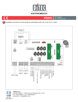
11. Example of a connection with radar and photocells 29
12. Troubleshooting / Alarms 30
13. Routine maintenance plan 32
i
This symbol indicates instructions or notes regarding safety, to which special atten-
tion must be paid.
This symbol indicates useful information for the correct functioning of the product.
All the rights concerning this material are the exclusive property of Entrematic Group AB.
Although the contents of this publication have been drawn up with the greatest care, Entrematic Group AB can-
not be held responsible in any way for any damage caused by mistakes or omissions. We reserve the right
to make changes without prior notice.
Copying, scanning or changing in any way is expressly forbidden unless authorised in writing by Entrematic
Group AB.

5
IP2239EN - 2016-05-11
1. General safety precautions
This assembly and installation manual is intended exclusively for the use of qualified personnel.
Installation, electrical connections and adjustments must be performed by qualified person-
nel, in accordance with Good Working Methods and in compliance with the current regulations.
Read the instructions carefully before installing the product.
Incorrect installation could be dangerous.
The packaging materials (plastic, polystyrene, etc.) should not be discarded in the environ-
ment or left within reach of children, as they are a potential source of danger.
Before installing the product, make sure it is in perfect condition.
Do not install the product in explosive areas and atmospheres: the presence of inflammable
gas or fumes represents a serious safety hazard.
Before installing the motorisation device, make all the necessary structural modifications to
create safety clearance and to guard or isolate all the crushing, shearing, trapping and general
hazardous areas.
Make sure the existing structure is up to standard in terms of strength and stability. The mo-
torisation device manufacturer is not responsible for failure to observe Good Working Methods
when building the frames to be motorised, or for any deformations during use.
The safety devices (photocells, safety edges, emergency stops, etc.) must be installed taking
into account the applicable laws and directives, Good Working Methods, installation premises,
system operating logic and the forces developed by the motorised door or gate.
The safety devices must protect against crushing, cutting, trapping and general danger areas
of the motorised door or gate.
Display the signs required by law to identify hazardous areas.
Each installation must bear a visible indication of the data identifying the motorised door
or gate.
When necessary, connect the motorised door or gate to an effective earthing system that com-
plies with the current safety standards.
During installation, maintenance and repair operations, cut off the power supply before opening
the cover to access the electrical parts.
The automation protection casing must be removed by qualified personnel only.
The electronic parts must be handled using earthed antistatic conductive arms. The
manufacturer of the motorisation device declines all responsibility if component parts
not compatible with safe and correct operation are fitted.
Only use original spare parts when repairing or replacing products.
The installer must supply all information concerning the automatic, manual and emergency op-
eration of the motorised door or gate, and must provide the user with the operating instructions.
Failure to respect the information given in this manual
may cause personal injury or damage to the device.
Keep these instructions for future reference

6
IP2239EN - 2016-05-11
2. List of tools
Tape measure
Pencil
10mm open-end spanner
3mm Allen key
10mm embedded hexagon Allen key
TORX T20 spanner
Drill
Scissors
Saw

7
IP2239EN - 2016-05-11
3. Contents of the kit
12345678
9
10 9
10
11
12 2
13
7m
x2
x2
x2
TX RX
x2
16
1
17
19
8
14
15
18
A
B
C

8
IP2239EN - 2016-05-11
Ref. Description Qty
BOX - A 1 Beam profile L = 4400mm 2
BOX - B 14 Cover profile L = 4400mm 2
BOX - C 2 End stop 2
3Power supply unit 1
4Gearmotor 1
5Control panel 1
7Carriage 4
8Belt 1
9Belt connection bracket 2
10 Belt restrainer hook 2
12 Belt transmission 1
13 Carriage anti-derailing device 4
15 Cover end plate 2
16 Function selector switch COM500MKS 1
17 Pair of photocells 2
18 Cover supports 2
19 Cover restraints 5
Connection cables 3
Cable fastener 10
Cable fastener ties 15
M6x16 screws 4
Ditec Entrematic logo 1
Technical manual 1
User manual 1
OPTIONAL ACCESSORIES
6Batteries DAS901BAT1 1
11 Anti-panic block DAS801LOKA 1
Standard block DAS801LOK complete with release cord 1
The given operating and performance features can only be guaranteed with the use of DITEC
Entrematic accessories and safety devices.
Unless otherwise specified, all measurements are expressed in mm.

9
IP2239EN - 2016-05-11
Ref. Code Description
1 Ditec DAS107 Automation for sliding doors
2 COM500MKS Function selector switch
3Photocells
4Opening sensors
A
Connect the power supply to an approved omnipolar switch with an opening distance of the contacts of
at least 3mm (not supplied). The connection to the mains must be made via an independent channel,
separated from the connections to command and safety devices.
4. Standard installation
1
4
2
3
A

10
IP2239EN - 2016-05-11
Ditec DAS107
Power 110V~ ÷ 220V~ ±10% ; 50/60 Hz
Rated power max. 100W
Max. load 1 door wing 120kg
Max. load 2 door wings 80kg / door wing
Temperature -20°C / +50°C
Degree of protection IP20
Power supply for accessories 24V 1A
Max speed 0,5 m/s (1 wings) ; 1,0 m/s (2 wings)
Intermittance S3=100%
Minimum number of maneuvers in AVERAGE
conditions of use 1.000.000 cycles* (2 wings x80 kg/1 wing x100 kg)
5. Technical specifications
6. Assembling the automation
Cut the beam profile to the size shown.
To make it easier to fix the beam to the wall, it is useful to drill holes of Ø 8mm every 400mm.
NB: remove any cutting residue from the aluminium, cleaning the carriage slide guides in particular.
Cut the cover profile to the size shown.
* test carried out by Entrematic Italy laboratory
LT-14
6.1 Cutting and preparing the beam
6.2 Cutting and preparing the cover
LT-10

11
IP2239EN - 2016-05-11
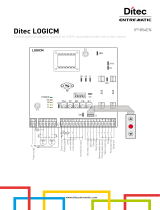
Automation with two door wings
LT PL LM B C D E F S
*2400
2PL+2S+20+400
940
LT/2-S-210
520
PL/2+S
80
C-340
420
LT/2-PL/2-310
580
C+160
960
C+540
350
(LT/2)-(PL/2)+380
50
*2600 1040 570 130 470 630 1010 400 50
*2800 1140 620 180 520 680 1060 450 50
*3000 1240 670 230 570 730 1110 500 50
2800
2PL+2S+20
1340
LT/2-S-10
720 80 420 580 960 350 50
3000 1440 770 130 470 630 1010 400 50
3300 1590 845 205 545 705 1085 475 50
3600 1740 920 280 620 780 1160 550 50
4000 1940 1020 380 720 880 1260 650 50
4400 2140 1120 480 820 980 1360 750 50
PL
LM LM
LT
55 55
SS
OPEN OPEN
B F
C
D
E
3 4 5 6
1
12
11
22
The values shown here are calculated by considering an overlap of S=50
*Lenght increased compared to the obatined opening passage due to power supply dimension.
53
LM
OPEN
53
53 53
LM
OPEN
9 9 8 7

12
IP2239EN - 2016-05-11
Automation for a single door wing with right-hand opening
LT PL LM A B C D E F S
2000
2PL+3S+20
915
(LT-3S-20)/2
1015
PL+2S
30 370
C-340
710
LT-LM-325+S
870
C+160
1250
C+540
40 50
2200 1015 1115 30 470 810 970 1350 40 50
2600 1215 1315 30 670 1010 1170 1550 40 50
3000 1415 1515 30 870 1210 1370 1750 40 50
3300 1565 1665 30 1020 1360 1520 1900 40 50
3600 1715 1818 30 1170 1510 1670 2050 40 50
4000 1915 2015 30 1370 1710 1870 2250 40 50
4400 2115 2215 30 1570 1910 2070 2450 40 50
The values shown here are calculated by considering an overlap of S=50
PL
LM
LT
S
55 55
S
OPEN
B
AF
C
D
E
3 4 5 6 12112 21
SET MENU =
53110
LM
OPEN
7 9 811

13
IP2239EN - 2016-05-11
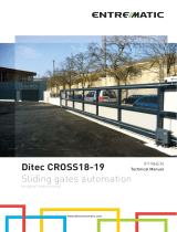
Automation for a single door wing with left-hand opening
LT PL LM A B C D E F S
2000
2PL+3S+20
915
(LT-3S-20)/2
1015
PL+2S
40 1780
C+340
1440
LT-LM-15+420+S
1280
C-160
900
C-540
120 50
2200 1015 1115 40 1880 1540 1380 1000 120 50
2600 1215 1315 40 2080 1740 1580 1200 120 50
3000 1415 1515 40 2280 1940 1780 1400 120 50
3300 1565 1665 40 2430 2090 1930 1550 120 50
3600 1715 1815 40 2580 2240 2080 1700 120 50
4000 1915 2015 40 2780 2440 2280 1900 120 50
4400 2115 2215 40 2980 2640 2480 2100 120 50
The values shown here are calculated by considering an overlap of S=50
PL
LM
LT
S
5555
S
OPEN
B
A
F
C
D
E
3 4 5 6 72 21 11
11053
LM
OPEN
7 98 11

14
IP2239EN - 2016-05-11
6.3 Assembling the carriages
Assemble the anti-derailing wheel [13] on the carriages, in the position shown in the figure.
13
7
6.4 Assembling the transmission
Position the transmission as shown at page 11, 12, 13 in position [F].
12

15
IP2239EN - 2016-05-11
6.5 Assembling the belt
Example for an automation with two door wings
Insert the belt in the motor pulley (to make this operation easier, turn the pulley).
Wrap the belt around the transmission.
Join the belt ends in line with the belt connection brackets [9], and lock it in place with the belt
restrainer hook [10]. Cut off any excess.
9
7
10

16
IP2239EN - 2016-05-11
6.6 Installing the door wing block (optional)
6.7 Installing the end stops
The door wing blocking device can be fitted to keep the door closed.
The automation automatically recognises the blocking device and acts properly.
- Fasten the door wing blocking device inside the box by means of the screws supplied.
- Place the door wing in the closure position.
- Check that, with the door closed, the block is resting correctly on the block hook-up bracket,
preventing the door from sliding.
- Make the electrical connections as explained in chapter 8.1.
For more information, refer to the blocking device manual.
Insert the end stops [2] in the beam profile and fix them in place.
Refer to the images on pages 11-12-13 for the correct positioning.
22
11
2
LEFT RIGHT

17
IP2239EN - 2016-05-11
6.8 Assembling the cover supports
Insert the cover supports [19] in the cover profile and fix them in place (A) near the end plate, as
shown in the figure.
Use the screws supplied to fix the heads to the casing profile, as shown.
Insert the cover restraints (20) along the cover profile.
To fix the cover to the beam, push up the support 18, insert it in the beam and fix it by screws (B).
18
(x2) (x5)
19
18
B
A
fascetta
stringicavo
15
18
19
Insert the cover support (18) at the ends of the guide of the cover.
Screw the end plate (15) to the cover.
cable fasteners
cable
fasteners
ties

18
IP2239EN - 2016-05-11
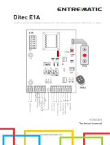
7.1 Beam fastening
7. Installing the automation
HM = H-40
H = HM+40 65
65
10
140
120
+/-7 +/-6
• Establishing the fixing height from the highest point of the finished floor.
• Measure the height, including the door wing connection. The installation height is equal to
HM+40mm.
• Fix the beam profile in the points indicated, using wall plugs and bolts. NB: the heads of the
screws/bolts must not be more than 6.5mm.
• Distribute the fixing points every 400mm, and at different heights if necessary.
• Make sure the top surface of the beam is perpendicular with the floor and not deformed
lengthwise with the shape of the wall. If the wall is not straight and smooth, iron plates must
be fixed to it and then the guide in turn fixed to the plates.
NOTE: the maximum space for the wings between cover and beam is 65mm.
WARNING: The fastening of the beam to the wall must be suitable in order to sustain the weight
of the door wings.

19
IP2239EN - 2016-05-11
7.2 Installing and adjusting the door wings
Fix the carriages to the door wings as shown in the figure.
53
110
53
53
53
53
53
110
OPEN OPEN
OPEN
OPEN
AUTOMATION WITH TWO DOOR WINGS
AUTOMATION WITH ONE DOOR WING WITH
RIGHT-HAND OPENING
AUTOMATION WITH ONE DOOR WING WITH
LEFT-HAND OPENING

20
IP2239EN - 2016-05-11
7.3 Adjusting the belt
The vertical position of the door wing can be adjusted, as shown in the figure.
Loosen the screws [A] and adjust the height with the screws [B].
Move the door wing manually to make sure the movement is free and without friction, and that all
the wheels (including the anti-derailing wheel) are resting on the guide.
A
B
+/- 6
Adjust the belt tension by means of the screw [A].
WARNING: incorrect adjustment impairs the correct functioning of the automation.
A
I
I
I
I
I
I
I
I
I
I
I
I
I
I
I
I
I
I
Torque:
for opening passage PL ≤ 1400mm --> 0,5 Nm
for opening passage PL > 1400mm --> 1,0 Nm

21
IP2239EN - 2016-05-11
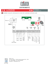
8. Electrical connections
Connect the automation to an efficient earthing system that complies with current safety
standards.
During installation, maintenance and repair operations, cut off the power supply before opening
the cover to access the electrical parts.
The automation protection casing must be removed by qualified personnel only.
An omnipolar disconnection switch with a contact opening distance of at least 3 mm must be
fitted on the mains supply.
Check there is an adequate residual current circuit breaker and overcurrent cut-out upstream
of the electrical system.
Make sure the yellow/green conductor is at least 3 mm longer than the brown and blue con-
ductors.
Install an electric switch next to the automatic system.
• Connect an electric cable – type H05RN-F 3G1,5 or H05RR-F 3G1,5 – to the terminals L
(brown), N (blue), (yellow/green) on the power supply connector.
Make sure there are no sharp edges that may damage the power supply cable.
If the power cable is damaged, have it replaced by the manufacturer or qualified personnel.
• Connect the power cable [1] to the terminal board [2].
• Connect the connection cable [3] to the power supply unit [4].
1
3
2NL
4

22
IP2239EN - 2016-05-11
Make the connections indicated.
Output Description
A
Power supply unit connection
B
Motor connection
C
Encoder connection
green LED
D
Function selector switch connection
For connecting COM500MKS selectors up to a 50m max distance.
E
Connection of battery kit DAS901BAT1 (12V)
To charge the batteries, connect the mains power and the battery kit at
least 30 minutes before starting the system.
With the mains power supply off, the automation will carry out an ope-
ning operation at low speed and remains open ( except when program
selector in “door closed” position)
WARNING: for charging purposes, the battery kit must be connected
to the control panel at all times. Periodically check the efficiency of
the battery kit.
NOTE:
Battery type: 12V, 1,2mAh NiMH.
If a different type of battery is used it can damage!
Power supply
Motor
Control panel
COM500MKS
DAS901BAT1 (12V)
(optional)
A
D
E
C
B
/