Page is loading ...

EN - Programming and operations manual
Uninterruptable power supply
DC Power Supply with
HyCharger™ DC
DC Power Supply

HyCharger DC Components 115V & 208/230V
HyCharger DC Supplement
iiii support.hysecurity.com
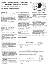
Internal & external wiring not shown.
Drawing is not to scale
Two 12V, 110Ah AGM batteries
Power disconnect
switch
Electrical panel
DC Power Supply cabinet
DC motor
circuit breaker
STC & accessory
24V Fuse (5A)
Line voltage
fuse (25A)
AC power
input terminal
strip
Heater strip
beneath shelf
Protected AC
terminal strip
Equipment ground
Power loss & DC
power terminal
Cooling fan
IMPORTANT NOTE: This document is a supplemental document that provides site planning specications and other references for the
DC Power Supply with HyCharger DC. For safety considerations and information specic to your gate operator, refer to the HySecurity gate
operator's Installation Instructions and Programming and Operations Manual.

DC Power Supply Cabinet Mounted on Posts
Introduction iiiiii
MX3645-01 Rev.E ©2023
Internal & external wiring not shown.
Drawing is not to scale. DC Power Supply cabinet
can also be wall-mounted.
Concrete pad
Conduit
Support posts Voltage identication label

Installer’s CheCklIst For DC Power suPPly wIth
hyCharger DC
Date Installed: __________________________________________ Gate Operator: ___________________________________________
Site Location: ___________________________________________ Serial Number: ___________________________________________
Date Installed DC Power Supply with HyCharger DC: _____ Serial Number: ___________________________________________
Customer Name: _______________________________________________________________________________________________________
Mailing Address: ________________________________________ Inspected by: ____________________________________________
________________________________________________________ Date Inspected: __________________________________________
Phone Contact: _________________________________________ Phone contact number: ___________________________________
Checked Initials
1. Site Planning _____________
Concrete pad poured.
Conduit and appropriate wire size installed. Refer to gate operator manual for wire size charts
2. Safety _____________
Review Important Safety Information.
Warning labels apparent and afxed properly.
Area around equipment free of debris, cabinets/chassis include locking mechanism.
3. Electrical _____________
3.1 Measure Input Voltage
Single phase: (check all boxes that apply),
115V 208/230V 50Hz 60Hz 20A
3.2 Input Power Connections
Input power properly connected.
L1 and L2 / Neutral and T1 and T2, Ground wired per illustration on UPS to Gate Operator Wiring on page 25.
3.3 Grounding
• NFPA 780 Standard for the Installation of Lighting Protection Systems.
• Solid copper ground rod (C\,-inch diameter, 10 ft length) driven into ground within 3 ft of the operator.
• Single length of unspliced 6AWG copper wire less than 3 ft long attached to lug nut in operator.
3.4 Gate operator using Smart Touch Controller has the most current software loaded.
3.5 Congure the Smart Touch Controller
• Set the Power Loss function (AP) in the User Menu. See page 22.
• Access the Installer Menu and select the type of power that the operator uses to AD 2. See page 24.
4. Review gate operator installation checklist _____________
5. Photographs of installation and End User Demo _____________
HyCharger DC Supplement
iviv support.hysecurity.com

Contents
Installer’s Checklist For DC Power Supply with HyCharger DC .......................................................................................iv
Welcome to HySecurity ...........................................................................................1
Introducing HyCharger DC ..............................................................................................................................................1
Intelligent Features ..........................................................................................................................................................2
Notices and Bulletins .......................................................................................................................................................2
Contact Information .........................................................................................................................................................2
Supplemental Documents ................................................................................................................................................2
IMPORTANT SAFETY INFORMATION .............................................................................................................................3
Prevent Electrical Shock ...............................................................................................................................................3
Emergency Stop and Manual Release..............................................................................................................................4
Hazardous Materials and Proper Disposal .......................................................................................................................4
Safety Notices ..................................................................................................................................................................5
Common Industrial Symbols ............................................................................................................................................5
Tools Required .................................................................................................................................................................6
inStallation overvieW ..............................................................................................7
Site Overview & Planning .................................................................................................................................................7
Battery Safety and Longevity ...........................................................................................................................................7
Site Overview & Planning: DC Cabinet Install .................................................................................................................9
SlideDriver: Right Handing Conguration ..................................................................................................................11
SlideDriver: Left Handing Conguration .....................................................................................................................12
HydraSupply XL Site Overview ......................................................................................................................................13
PoWer ..................................................................................................................15
Site Considerations ........................................................................................................................................................15
UPS to Gate Operator Wiring .......................................................................................................................................15
Installing the Earth Ground ...........................................................................................................................................16
SlideDriver: Wiring AC, 115V HyCharger DC ................................................................................................................17
SlideDriver: Wiring AC, 230V HyCharger DC ................................................................................................................18
HydraSupply XL: Wiring Diagram DC Single .................................................................................................................19
HydraSupply XL: Wiring Diagram DC Twin ....................................................................................................................20
HyCharger DC Power .....................................................................................................................................................21
Gate Operator AC Power ...............................................................................................................................................21
Turning the Power ON ...................................................................................................................................................21
Test the Gate Operator ..................................................................................................................................................22
Table of Contents vv
MX3645-01 Rev.E ©2023

DiSPlay & menu oPtionS ........................................................................................19
Initial Setup ....................................................................................................................................................................19
Gate Operator Display and Keypad ..............................................................................................................................19
Menu Mode and the STC Keypad ................................................................................................................................20
Menu Mode Navigation .................................................................................................................................................20
Run Mode and the STC Keypad ...................................................................................................................................21
Check Time and Date .................................................................................................................................................21
Stop the STC Status Display Scroll..............................................................................................................................21
Change the Contrast on the 7-Segment STC Display ................................................................................................21
AC Power Loss Function: User Menu .............................................................................................................................22
User Menu, AP: Table 1, OLED and 7 Segment Displays ...........................................................................................22
AP Menu, AC Loss: Table 2, Conguring DC Power...................................................................................................23
Installer Menu ................................................................................................................................................................24
Installer Menu: Table 3, OLED and 7 Segment Displays ............................................................................................24
troubleSHooting ...................................................................................................25
System Diagnostic Messages .........................................................................................................................................25
Troubleshooting Codes: Table 6 .................................................................................................................................26
Mechanical Issues and Hydraulic Issues .........................................................................................................................26
general maintenance ..........................................................................................27
Battery Maintenance ......................................................................................................................................................27
Replacing the Batteries ..................................................................................................................................................28
Specications .................................................................................................................................................................30
HyCharger DC Supplement
vivi support.hysecurity.com

Safety 11
MX3645-01 Rev.E ©2023
Welcome to HySecurity
Thank you for your recent purchase of the HyCharger DC™. Housed in our HySecurity Gate, Inc. DC Power
Supply Cabinet, the HyCharger DC assures operational integrity at your hydraulic gate site. This supplemental
manual provides an overview for site planning and presents the power requirements and operational
programming available with the HyCharger DC system.
For safety information and additional instructions regarding the hydraulic operator powered by the unit, refer to
your gate operator’s product manual.
HySecurity Gate, Inc. Headquarters in Kent, WA
IntroDuCIng hyCharger DC
The latest offering for DC-powered hydraulic operators meets or exceeds ETL requirements and provides
unparalleled user benets:
Smart – Smart charge system using high efciency switching technology that optimizes battery conditioning,
storage capacity and battery life.
Power – Supplies 50A of 24VDC power on continuous basis to both motor drive circuit or charger circuit. Burst
mode supplies additional energy to gate operator when needed.
Robust – The electronics and batteries are rated for temperatures ranging from -40°F to 158°F (-40°C to 70°C).
A heater strip attached to the base of the shelf automatically turns on to keep batteries at optimal operating
temperature.
Adaptable - Easy replacement of existing, older DC chargers in HySecurity DC Supply Cabinets. If you are
interested in replacing an older DC charger, contact HySecurity for replacement parts:
MX2890-01 HyCharger DC 230V or MX2890-02 HyCharger DC 115V

HyCharger DC Supplement
22 support.hysecurity.com
IntellIgent Features
• Multi-stage charging
• Redundant chargers
• Battery Voltage sensing
Fast recharge - After AC power is restored, batteries are completely recharged in as little as 2 hours (12 hours
when operating a high-trafc gate).
Temperature control - A heater and fan are standard features and automatically turn on to keep the interior of
the cabinet at temperatures that are optimal for maintaining and sustaining a long battery life and charge.
S.T.A.R.T. software and diagnostics - With S.T.A.R.T. software loaded on a PC laptop computer, you have an
invaluable management tool for all HySecurity operators. To download this free software, visit the HySecurity
website: www.hysecurity.com.
notICes anD BulletIns
Installers should visit HySecurity’s online Technical Support page at www.hysecurity.com or contact HySecurity
prior to installing product to make sure they have received the most up-to-date information.
ContaCt InFormatIon
Before contacting your distributor or HySecurity Technical Support, obtain the serial number of your operator.
Qualied HySecurity distributors are experienced and trained to assist in resolving any problems. For the name of
a qualied distributor near you, contact HySecurity at 800-321-9947.
For information about HySecurity training for installers, maintenance personnel, and end users, refer to the
company website at www.hysecurity.com.
suPPlemental DoCuments
The product literature is comprehensive and contains information needed to plan, install, operate and maintain
the HyCharger DC. Additional general information concerning HySecurity hydraulic gate operators or the
HyCharger DC can be obtained from the following:
• HySecurity web site www.hysecurity.com - Contains links to the product catalog, product order form,
operator manuals, operator software downloads, technical support bulletins and other useful information.
• S.T.A.R.T. - Smart Touch Analyze and Retrieve Tool - User’s Guide (D0049) detailing the extensive software,
diagnostic and troubleshooting capabilities of the Smart Touch Controller board.
• Technical Bulletins (as applicable).
NOTE: Technical Bulletins are automatically issued to registered users of HySecurity products. The product warranty registration card
can be lled out online at www.hysecurity.com.

Safety 33
MX3645-01 Rev.E ©2023
ImPortant saFety InFormatIon
WARNING
Read all the product safety information prior to installation. Automatic gate operators move the gate with high
force and can cause serious injury and death! Make sure the automatic gate operator is installed to reduce the
risks of entrapment. Verify the gate operator is installed to comply with all safety standards and local and federal
regulations.
Understand that you as the site designer, installer, maintenance crew, or owner/user must consider the risks
associated with gate operators. Be sure to take responsibility, read, and follow the Important Safety Information
found in the gate operator’s manual and review all the literature that accompanies the product.
Hazards, associated with automatic gates, can be reduced with proper site design, installation, and use. It is
important that only qualied installers handle the installation of the HySecurity equipment and gate operators.
A “qualied” installer has one of the following:
• A minimum of three years experience installing similar equipment
• Proof of attending a HySecurity Technical Training seminar within the past three years
• Signicant manufacturer endorsements of technical aptitude in gate operator installation and operation
Underwriter Laboratories (UL) and the American Society for Testing and Materials (ASTM) are responsible for
current safety standards and regulations regarding automatic vehicular gate operators. To pass certication, all
aspects of gate operator and gate installation must comply with the appropriate safety standards.
For the most up-to-date ASTM F2200 Gate and Fence Standards, refer to www.astm.org
For UL 325 Safety Standards, refer to www.ul.com
Prevent Electrical Shock
To stop the ow of electricity, turn off the main disconnect power switch found in the DC
Supply Cabinet. The Power disconnect switch only disconnects power to the operator. If you
are performing routine maintenance or more extensive repairs always be sure to turn OFF
the main AC power to the gate operator and DC Power Supply. For additional information,
refer to Battery Safety and Longevity on page 7.
Residual amounts of electricity reside in the batteries even when the AC power switches are turned off. If
shorted, the batteries can deliver very high currents. Exposed connector pins must be handled with extreme care
and caution; they can be easily shorted against any metal surface. If a short circuit persists beyond a second,
connectors, cables, and tools can be damaged or destroyed. Fire and personal injury may result and potential for
electrical shock exists.
This manual is a supplement to the gate operator. Read and follow the Important Safety Information found in the
gate operator’s Programming and Operations Manual.
WARNING
Power disconnect switch

HyCharger DC Supplement
44 support.hysecurity.com
emergenCy stoP anD manual release
No emergency stop or manual release is found in the DC Power Supply cabinet. The gate operator’s emergency
stop button is strategically placed on the outside of the gate operator and its manual release location is
dependent on the type of gate operator. Refer to the gate operator’s product manual for more information.
hazarDous materIals anD ProPer DIsPosal
Be aware of the international, federal, and local codes in your area and how best to handle hazardous waste
materials.
HyCharger DC uses sealed, state-of-the-art Absorbed Glass Mat (AGM) batteries and highly recommends
replacing used batteries with new AGM-type batteries.
CAUTION
If the gate operator has a battery backup system, the batteries contain materials that are considered hazardous
to the environment. Proper disposal of the battery is required by federal law. In the U.S.A., refer to federal EPA
guidelines for proper hazardous waste disposal.
To reduce the risk of re or injury to persons:
• Observe the polarity between the batteries and charging circuit.
• Never mix battery sizes, types, or brands. Only sealed AGM style batteries should be used.
• Exercise care in handling batteries. Be aware that the metal found in rings, bracelets, and keys can
conduct electricity, short the batteries, and cause potential injury. Remove metal objects from your person
before working or handling items in the DC Supply Cabinet.
• Do not open or mutilate the batteries. Battery cells contain corrosive materials which may cause burns
and other injuries. The material within batteries is toxic and considered hazardous waste material.
• Always dispose of batteries properly. Do NOT place batteries in re. The battery cells may explode.
Follow federal guidelines for proper disposal of hazardous waste.
• Replace batteries according to the instructions found in Replacing the Batteries on page 28.

Safety 55
MX3645-01 Rev.E ©2023
saFety notICes
The following four levels of safety notices are used where applicable within this manual; each notice contains
information specic to the situation.
DANGER
Indicates death or serious injury will occur if the hazardous situation is not avoided.
WARNING
Indicates death or serious injury could occur if the hazardous situation is not avoided.
CAUTION
Indicates mild or moderate injury could occur if the hazardous situation is not avoided.
NOTICE: Indicates damage to equipment is probable if the hazardous situation in not avoided.
Common InDustrIal symBols
The following international safety symbols may appear on the product or in its literature. The symbols are used
to alert you to potential personal injury hazards. Obey all safety messages that follow these symbols to avoid
possible injury or death.
Attention
- Take Note -
- Danger -
Keep Away Entrapment
Zone Possible
Pinch Point
Ground
Symbol
O
Electrical Phase
Symbol

HyCharger DC Supplement
66 support.hysecurity.com
tools requIreD
• Standard socket set (>\zn-inch combo wrench, M\zn-inch socket wrench, two M\zn-inch box end wrenches)
• Crescent wrench
• Phillips head screwdriver
• Flat head screwdriver
• Wire cutter and wire nuts

Installation Overview 77
MX3645-01 Rev.E ©2023
Installation Overview
Gate operators equipped with the HyCharger DC option are powered by two 12-Volt, 110Ah DC batteries which,
when AC power loss occurs, maintain a true Uninterrupted Power Supply (UPS) system. When the local AC
power fails, the UPS back up system continues to move the gate. To review system features, refer to Introducing
HyCharger DC on page 1. See specications on the back cover for backup gate travel capacity.
NOTE: The HyCharger DC option is not available for gate operators using Variable Speed Drives (VFD).
sIte overvIew & PlannIng
• Place cabinet within 10 ft (3 m) of the gate operator. Contact HySecurity Technical Support if distance
between gate operator and HyCharger DC needs to be greater than 10 feet.
• Locate concrete footings a minimum of 16 inches (41 cm) deep or to frost line per local codes.
• At minimum, use 4-inch (10 cm) diameter support posts for DC Power Supply cabinet. Support posts and
hardware are not provided by HySecurity. Neither is wall mounting hardware.
• DC Power Supply cabinet can also be wall-mounted.
• Provide additional 2-inch (5 cm) round conduit for wires between the DC Power Supply cabinet and gate
operator. Six wire conductors are required:
Control Panel: Two each, 14 AWG minimum
Control Panel Power: Two each, 14 AWG minimum
Motor: See table for wire size.
NOTE: See Power on page 25 for additional site considerations.
Battery saFety anD longevIty
Residual amounts of electricity reside in the batteries even when power switches are turned off. If shorted, the
batteries can deliver very high currents. Exposed connector pins must be handled with extreme care and caution;
they can be easily shorted against any metal surface. If a short circuit persists beyond one second; connectors, cables,
and tools can be damaged or destroyed. Fire and personal injury may result and potential for electrical shock exists.
Remove all metal objects from your person before servicing the DC Power Supply with HyCharger DC.
• Control of the load is important since the gate operator may need to run on backup batteries. Gates that
move easily and do not bind will drain less energy from the battery, preserving capacity for more cycles
during a power failure.
• Be certain to observe polarity when connecting the batteries or adding accessories. Reversed polarity may
result in a non-functional operator or damage to a component. Red (+) is positive and black (-) is negative.
If shorted, the batteries will generate a very high current. The batteries are connected in series on each
shelf. Each battery “shelf” is connected to the other in parallel. See
.
WARNING

HyCharger DC Supplement
88 support.hysecurity.com
• Variations in temperature affect battery performance! Batteries have a nite life and age more
quickly when exposed to temperatures above 80°F (27°C). A fan automatically turns on when internal
cabinet temperature exceeds 110°F (43°C), +/- 5°. To provide residual heat inside the enclosure,
HySecurity mounts a heater beneath each battery shelf which turns on when temperatures dip below 32°F
(0°C), +/- 5°. An example of amp hour (Ah) performance is shown in the chart below.
Example of Battery Performance:
Temperature Capacity
77°F (25°C) 100%
32°F (0°C) 80%
-22°F (-30°C) 50%
• As the batteries age, they will progressively lose their capacity to store energy. If the total amount of
back up capacity is critical, plan to replace the batteries after two years of use, especially in hot climates.
Properly discard used batteries. See Hazardous Materials and Proper Disposal on page 4.
• Batteries contain sulfuric acid. Acid in your eyes, on your skin, or on your clothing can cause injury and
severe burns. If batteries are dropped or damaged dispose of them properly.
• HySecurity uses permanently sealed AGM batteries which last longer than wet cell batteries and require
no maintenance over their life span. Batteries are protected from over discharge by smart system charger.

Installation Overview 99
MX3645-01 Rev.E ©2023
sIte overvIew & PlannIng: DC CaBInet Install
NOTE: Consult with local site engineers for pad size if pole height extends beyond 54 inches
(137 cm)
Drive rail
Example:SlideDriver gate operator
Offset 4½ (114 mm)
Support post 4 inch
diameterHeight:54 inches
minimum (137 cm)
Wheel and cover
Cantilever gate (4 wheel)
Gate panel
Support posts 4 inch
diameter
DC
Supply
Cabinet
Raised concrete pad
Street grade
6 inches (15 cm)
minimum
Height from top of drive rail
to base of gate operator. All
SlideDriver models: 9¼ in (235 mm)
Unistrut attached
to cabinet ange.
Installer supplies,
Unistrut, U-bolts
and fasteners.
Covered
wheel
Concrete pad
(above & below grade)
Cross sectional view
Concrete pad below grade must
extend, at minimum, to frost
depth (per local codes), or 24"
(61 cm) whichever is greater.
30 inch minimum (76 cm)
13½ inches
(34 cm)
1⅞ inches
(5 cm)
1¼ inches
(3 cm)
Flange
Door
clip
C/LC/L
13½ inches
(34 cm)
C/L
DC Supply Cabinet
C/L
Flange
Unistrut U-bolt
Wall or post-mount DC Supply Cabinet.
If planning a post mount, mounting holes
need to be drilled (U-bolts, fasteners, and
Unistrut are not provided) Three mounting
holes on anges are ⅜-inch diameter.
30 inches
(76 cm)
12 inches
(30 cm)
M|, inch
(22 mm)
M|, inch
(22 mm)
DC Power Supply Cabinet
Dimensions: Inches: 30W x
30H x 12D (Centimeters: 76W
x 76H x 30D)

HyCharger DC Supplement
1010 support.hysecurity.com
SLIDEDRIVER
FACE OF GATE
CONDUIT
AREA
slIDeDrIver sIte overvIew
Un-interruptible
Power Supply
(UPS)
Conduit cutout for electrical access. Cut out
dimensions: 8 x 7½ inches (10 x 19 cm)
Shown: Post-
mounted.
U-bolts
mounted
to Unistrut
on back of
cabinet.
Cabinet may
also be wall-
mounted with
anchor bolts.
Minimum clearance 30
inches (76 cm)
30 inches (76 cm)
Door swing Concrete pad extends 2 inch (5 cm) minimum beyond
side and front of gate operator chassis’ footprint.
Conduit runs between gate operator and cabinet.
Support post
Gate panel
Drive rail
Close
direction of
gate
Allow 12 to 16
inches (30 to 41 cm)
Distance between gate face and
rear chassis: 1½ ± ⅛ inch (38 mm)
Obstructed area
Hydraulic motor location
Gate travel.
Close direction.
NOTE: DC Power Supply may be wall-mounted or post-
mounted. Maximum distance from gate operator is 10 ft (3
m). Dimension for concrete pad, dependent on site design.
8 inches
(20 cm)
30 inches (76 cm)
minimum
C/L
7¼ inches
(18 cm)
1¼ inches (3 cm)
1¼ inches (3 cm)
13 inches
(33 cm)
26 inches (33 cm)
C/L
1¼ inches (3 cm)
2 inches (5 cm)
2 inch (5 cm)
minimum
1½ inches (38 mm)
C/L
C/L
C/L
2 inches (5 cm)
5 inches (13 cm)
2 inches
(5 cm)
14½ inches (37 cm)
Minimum concrete dimensions
for SlideDriver: 20W x 30L X 16D
inches
(51 x 76 x 41 cm)
Mounting bolts (4x):
Four ½ x 4 inch anchor bolts
12 inches (31 cm)
minimum
Leave enough space between cabinet and
chassis to avoid pinch point and access issues.
Minimum 24 inches (61 cm)
SLIDEDRIVER
FENCE LINE
CAUTION
If you cut, drill, or alter the chassis, you will
void the Warranty.

Installation Overview 1111
MX3645-01 Rev.E ©2023
SlideDriver: Right Handing Configuration
The following illustrates the SlideDriver and HyCharger DC in a right handing conguration.
WARNING
The DC Power Supply cabinet is very heavy and requires either multiple personnel or separate lifting equipment
(recommended) to facilitate wall or post mounting. Failure to comply may result in serious injury to personnel,
damage to the equipment, or both.
Gate opening
(Right hand gate
shown.)
Gate panel Fence
Drive rail
Offset 3 inches (7.6 cm)
from the surface of the
support posts to rear of
SlideDriver chassis.
SlideDriver
HyCharger DC
Chassis base cut
out for conduit Clearances for HyCharger DC:
Door swing: Allow 30 inches (76 cm)
Rear access: Minimum 24 inches (61 cm)
Clearances for SlideDriver:
Side access: Minimum 24 inches (61 cm)
Front access: Allow 30 inches (76 cm)
UPS
Front View Rear View
SlideDriver
Transparent views of DC Supply Cabinet and SlideDriver

HyCharger DC Supplement
1212 support.hysecurity.com
Gate edge
Limit ramps
Drive rail
Left hand gate shown.
For a right hand installation, place the DC
Power Supply on the opposite side of the
SlideDriver.
DC Power Supply
Inches: 30W x 30H x 12D
Centimeters: 76W x 76H x 30D
SlideDriver (No 50VF - series)
Inches: 26W x 26H x 14½ D
Centimeters: 66W x 66H x 37D
Option:
SlideDriver Base Riser
Inches: 26W x 12H x 14½ D
Centimeters: 66W x 30H x 37D
Concrete pad
Conduit
CAUTION
Do NOT cut, drill or otherwise alter
the gate operator base; doing so may
compromise the structural integrity and
may void the limited warranty.
SlideDriver: Left Handing Configuration
The following illustrates the SlideDriver and HyCharger DC in a left handing conguration.
HyCharger
DC
Two 12V, 110Ah
Batteries
Concrete
pad SlideDriver
Conduit
beneath grade
The DC Power Supply cabinet (shown post-
mounted) can also be wall-mounted, but needs
to stay in close proximity, within 10 feet (3 m), to
the gate operator.

Installation Overview 1313
MX3645-01 Rev.E ©2023
hyDrasuPPly Xl sIte overvIew
16”
(41 cm)
48”
(121 cm)
Eye bolts used
for lifting
36”
(92 cm)
PUBLIC
SECURE
NOTE: Pay attention to and plan for clearance and access. Cabinets
shown post-mounted.
HydraSupply XL
Cabinet
Concrete pad
foundation
Roadway
Conduit runs between
HydraWedge SM50 and cabinet.
Wall
36” (91 cm)
minimum
Door swing
Optional Safety Skirt
Bollards
DANGER
Life-threatening danger due to incorrect installation and initial
commissioning. Installation errors and improper electrical connections
may cause life-threatening situations or a considerable extent of
property damage which is not covered by the Warranty. To mitigate
danger to life and property, thoroughly read the installation
instructions and the Important Safety Information found in the
HydraSupply XL Programming and Operations Manual. Plan site design
and construction for proper operation and HydraWedge SM50 and
HydraSupply XL commissioning. Consult with qualied and authorized
engineers.
DC Power Supply
HyCharger DC
Door swing
30” (76 cm)
minimum
Max. 10 ft (305cm)
HydraSupply XL Cabinet
Wall or post-mount the HydraSupply XL cabinet.
If planning a post mount, mounting holes need to be
drilled (U-bolts, fasteners, and unistrut are not provided).
Cabinet may also be wall-mounted with anchor bolts.
NOTE: The mounting holes on the top and bottom anges
are ½-inch diameter. For additional information, refer to
the HydraWedge SM50 Installation Instructions. An entire
page is devoted to HydraSupply XL installation.
13½ in
(34 cm)
1⅞ in
(5 cm)
1¼ in
(3 cm)
Door
clip
C/LC/L
Flange
Flange Unistrut U-bolt
36 in (92 cm)
HydraSupply XL Cabinet

HyCharger DC Supplement
1414 support.hysecurity.com
Page intentionally left blank
/