Page is loading ...

Sterling Power Products
Copyright
Pure Sine Wave Inverter / Charger MANUAL
Pro
Combi S+
STERLI G
POWER
Copyright © 2017
Sterling Power
V 4.0 July 2017 RoHS
compliant
www.sterling-power.com
www.sterling-power-usa.com
Warranty (2 years return to factory)
WARNING:
DO NOT OPEN UNIT | HIGH INTERNAL VOLTAGE | PLEASE READ AND UNDERSTAND THE INSTRUCTIONS PRIOR
TO INSTALLING OR OPERATING THIS PRODUCT | SHOULD ONLY BE INSTALLED BY A QUALIFIED PERSON
This Combi, when on inverter mode, is neutral
earth bonded for use with RCD and other types
of earth fault detectors.
This Manual applies to these models:
Languages:
Operation with a small generator ( Genset ).
The majority of none digital (non pure sine wave) generators from 1-10
KW have poor regulators and produce erratic wave forms when
presented with a inductive load. The wave form is simply not good
enough to run the Combi in battery charger mode. However, over the
years we have found that running an old style 50W light bulb in
conjunction with the generator output can settle the regulator on the
genset and the Combi will then, most likely work. Please note you still
need to ensure that your generator is powerful enough (continuous real
wattage, not VA).
www.sterling-power.com
www.sterling-power-usa.com
230V / 50Hz model
PCSP121600
PCSP241600
110V / 60Hz model
PCSPA121600
PCSPA241600
For the latest instructions, refer to the website
Auxiliary Charge Module (optional) Part no.
12V/24V Combi charger to 12V battery ~5A = ACM12
12V Combi charger to 24V battery ~3A = ACM1224
24V Combi charger to 24V battery ~3A = ACM2424
Contact Sterling Power or a Sterling dealer to purchase

Using the Instruction Manual
This manual must be read throughout before installing this
electronic device. Do not lose these instructions - keep them safe.
The most up to date instructions can be found on the Sterling Power
website. Please refer to the latest instruction manual before
contacting Sterling. At Sterling, we endeavour to include all of the
product information that we can think of into the manual.
Installation of the electronic device must be carried out by a
qualified and trained personnel only. The personnel must be
familiar with the locally accepted guidelines and safety measures.
Sterling Power’s warranty statement
A comprehensive warranty statement is provide at the back of the
instruction manual. A comprehensive warranty statement can also
be found on sterling-power.com.
Copyright and plagiarism
Copyright © 2015 Sterling Power. All rights reserved.
Reproduction, transfer, distribution or storage of part or all of the
contents of this document is strictly prohibited. If you wish to use all
of this document, or excerpts from it, Sterling Power must be
contacted.
Liability
Sterling Power can not accept liability for:
Ÿconsequential damage due to use of this device
Ÿpossible errors in the manuals and the results thereof
Device modification
Please do not modify the device unless you have been instructed to
do so by Sterling Power, directly. Product modification shall be done
at Sterling, when needed. Warranty shall be voided if personal
attempts are made to modify the device, without Sterling’s
approval.
Use the Pro Combi S+ Inverter/charger only:
ŸFor AC to DC charging.
ŸFor DC to AC conversion.
ŸWith fuses protecting the AC/DC cables.
ŸIn a well ventilated, dry, dust-free and condensation free
environment.
ŸWhen instruction manual has been read through.
Transport and storage
Ensure that the mains supply and battery leads are disconnected.
No liability can be accepted for damage in transit once equipment
has been unpackaged.
Store the product in a dry environment, between –20°C to 60°C.
Refer to the battery manufacturer's manual for information on
transportation, stowage, charge rates, recharging and battery
disposal.
Safety Symbols
ŸExample - WARNING. Never use the device in situations
where there is danger of gas / dust EXPLOSION or potentially
flammable products.
General maintenance and repair
The device must be switched off during maintenance. and all cables
removed from the direct feed to or from the unit It must also be
protected against unexpected switching off. Remove battery
connections and ensure unit is off. If repair is required, only use
original parts.
General safety and installation precautions
WARNING: these units are heavy, do not lift unassisted.
ŸCheck that your model is correct - 110V / 230V and 12V / 24V?.
ŸThe orientation of the unit it not critical.
ŸPlace as close to the house / domestic batteries as possible.
ŸEnsure Combi is off when installing.
ŸDisconnect AC wires whilst installing
ŸConnect AC output to Residual Circuit Breaker (RCD) and current
overload trips.
ŸWhen installing the DC cable, connect cable to the battery first,
have the appropriate fuse connected to this cable and then connect
to the inverter/charger - in that order.
ŸSterling recommend Multi Core Tri rated AC cable.
ŸInstall device in well ventilated space. Do not expose device to:
Rain, snow, spray, moisture, pollution, condensation.
ŸDo not cover or obstruct ventilation openings.
ŸDevice connects to common negative. Common negative must
be earthed.
ŸIn case of fire use a fire extinguisher suitable for electric fires.
ŸEnsure reverse polarity and short circuiting is avoided - to prevent
damage to battery.
ŸProtect DC and AC wires with the appropriate sized fuse.
ŸCheck cabling annually- fix where needed.
ŸAvoid contact with device with damp hands on DC side.
ŸEnsure the device is adequately and securely mounted to prevent
the unit from displacement.
ŸUse a professional to install device.
ŸSelect the correct battery chemistry profile before turning the unit
on.
Ÿ Turn the unit on before turning on the AC appliances connect to it.
Battery safety
Excessive charge or discharge and high voltages can cause serious
damage to batteries. Never exceed the recommended limits. If
battery acid contacts skin or clothing, wash immediately with soap
and water. If acid enters the eye(s), immediately flood the eye(s) with
running cold water for 20 minutes and seek medical attention. Give
extra care to not drop metal tools or jewellery on to the battery
terminals as short circuiting can take place.
Refrain from charging battery up to 4 hours prior of installation to
avoid the formation of explosive gases.
CAUTION
WARNING
EXPLOSION
Contents
Legal and Safety
2
Page 2 Legal and Safety - PLEASE READ
Read page before installation
Page 3 Quick Installation
Wiring diagram
Fuse and cab le sizes
Circuit b oard layout with key
Page 4 Installation
Insallation procedure
Battery chemistry tab le
Desulphation mode
Auxiliary battery charging mode
Comb i operation
Page 5 Additional Installation
Power Reduction mode
Auxiliary module installation
Unit Specification Chart
Page 6 LED Information + Alarms
Page 7 Remote Control Functions
Page 8 Warranty Statement

+ + + + + +
input output
L E N L E N
engine start
DC fuse
as close to
battery as
possible
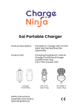
AC input:
230V/50-60Hz (check model)
Continuous through current
Max 16A AC on 1600
Shore power / gen set
110V/50-60Hz (check model)
Continuous through current
Max 32A AC on 1600
Shore power / gen set
FUSES
Quick Installation
House / Domestic
+ + +
L E N
AC INPUT
(SHORE POWER)
+ + +
L E N
AC OUTPUT
( to consumer unit
with RCD )
DC – DC +
1
6
7
8
DC low voltage AC high voltageWarning:
34
11
910 2
Alarm
(alarms on box )
fuse
10A
+ + + + + +
input output
AC 230V
power in
AC power out
AC 110V
power in
AC power out
L E N L E N
R.C.D. /
Earth Leak Detector
Please be aware that fuses are there mainly to protect your cabling, not the device.
L=Live
E=Earth
N=Netural
When the Combi is in inverter mode the
‘through the box’ earth line is
automatically disconnected from the
input earth and joined to the output
neutral. This complies with neutral
earth inverter requirements. If you wish
to maintain a through earth simply
connect the input earth and output
earth.
Auxiliary
Charging
Output
up to 5A Main
Charging
Output
When ordering the wire using one cable is always best. However, you can add up smaller cable’s mm
sq to equal the equivalent larger size. For example, if you want 100mm sq using 2x50mm sq would be
ample, likewise with 3x 33mm sq etc.. Do not forget that each cable shall need fusing at half (or a third
etc) of the single cable rating, its not safe to put multiple cables on a single fuse .
AC Cable 110V
12 AWG 3.5mmsq 30A
10 AWG 5.0mmsq 50A
AC Cable 230V
2.5mmsq for 16A
3.5mmsq for 30A
DC Cable Sizes and Fuses
NEG POS
5
12
4
2
3
AC input
AC output
MODEL DC Fuse size Cable size (0 -1.5m) Cable size (1.5 -4.0m)
PCSP(A)121600 200A 50mm2 / 0 AWG 70mm2 / 00 AWG
PCSP(A)241600 150A 35mm2 / 2 AWG 50mm2 / 0 AWG
1) AC input from shore. 7) Rotary switch for battery chemistry selection.
2) Fuse for inverter only (inside) non resettable. 8) Auxiliary charging output (positive only).
3) AC output to your RCD and distribution box. 9) DC negative battery connection.
4) Fuse resettable for through power protection. 10) DC Positive only.
5) Auxiliary charge power board (optional). 11) Reverse polarity tell-tale, warranty void if damaged.
6) Remote port for connecting the remote control. 12) Not Applicable

1) Firstly refer to the General safety and installation precautions part of the
Legal and Safety page before installing.
2) Ensure Combi is turned off whilst installing.
3) Acquire and install the correct sized Mulit Core Tri Rated cabling with the
correct fuses for DC (refer to cable / wire table associated with the wiring
diagram).
4) For AC, 30A supply use a 40A fuse. For a standard 13A-16A supply use a
20A fuse. Connect a Residual Current Device (RCD) or over-load trips to the
Combi’s AC output.
5) Connect the cables from the Combi to the fuses then to the battery, in that
order. If there is an isolation switch, connect this prior to connecting to
Combi. Ensure the isolation switch’s current rating is suitable for the Combi
being used.
6) Before initially turning the unit on, check that the correct battery charging
chemistry is selected, and do not connect AC input yet. see below:
7) Battery charging power reduction switch. To reduce the amount of AC
current required to run the charger you can turn the DC charge rating down
by 50%. For example, a normal 1000VA genset (800W) shall, realistically,
only run a combi charger at about 35-40A of DC charge at 15V. However, the
charger of the 1600 model is 70A, therefore, by applying the ~50% reduction
rate you can bring the charger rate down to ~40A – hence it can then operate
from the 1000VA genset. This can be extrapolated for larger scenarios
whereby a standard 13A 230VAC supply shall not run the 220A charger on
5000 model. This too, shall have to be set at the 50% reduction. There are
many other circumstances where reducing the DC rating is beneficial –
other examples include not over loading your AC supply and not utilising the
entire power of a genset to run the charger; you may wish to run other
appliances from the genset, simultaneously. See table below. Please note
the power reduction reduces the battery charging power only, it has no affect
on the inverter’s power ability.
Remember it is the voltages which are more important than our battery
types, our battery types are a simple generic recommendation. After
installation, test the voltage from the unit is the desired voltage. Ensure you
remove at least 1 wire from the battery temperature sensor as the
product voltage may be higher (if in cold climate) or lower (if in warn
climate) than the pre conceived voltage. The voltage requirements of the
battery company will override our recommendations as it is them who are
supporting the battery warranty. If in doubt, and until you have the
correct charging profile, select preset 1. Preset 1 is the lowest
charging voltage (the safest). Change to the correct profile when
known.
InstallationInstallation
Battery Chemistry Selection
If batteries are left undercharged or under used for a period of time, sulphate
crystals build up on the battery’s plates. This inhibits or slows the electrolysis
reaction thwarting the performance of the battery. To help combat this, a high
voltage (15.5V (x2 for 24V)) is applied. This is a very high voltage and the setting
should only be used if you know and understand what you are doing.
Procedure:
- Ensure the battery bank is totally isolated from anything else on the boat or
vehicle. It has the potential to cause damage to anything connected to the battery
bank in question (appliances / inverters / other batteries etc.)
- Ensure battery compartment is very well ventilated and battery caps are
removed.
- Switch the battery type selector switch to the correct position (8), then switch the
AC power on.
- There is a 4 hour time out period built into the software. If you have a very large
bank, you shall need to manually restart the cycle. NEVER LEAVE THE SYSTEM
UNATTENDED. IF THE TEMP OF THE BATTERY EXCEEDS 50C THEN STOP
THE PROCESS.
What to expect:
- The voltage on battery terminals should shoot up to ~15.5V (31.0V) immediately
(if the batteries are sulphated). After 1-2 hours at this voltage you should start to
see the voltage drop down to around 12.5V. It should then start to rise, more
slowly. This is a good sign and indicates that the battery is now receiving current.
once the procedure is completed the unit will stop working then Please restart
the Combi in the correct charging profile. You may have to cycle this a few times -
this is just a professional guess tool.
The auxiliary output is a positive 12V or 24V charging terminal that shall,
generally, be connected to the starter / cranking battery to keep it topped up. It
shall charge at a voltage slightly lower (0.3V) than the main Combi output. It is a
trickle / maintenance charger of about 5A at 12V (2.5A at 24V) and provides a
constant voltage. The Auxiliary Battery Charger is an optional module that can be
purchased from Sterling or from one of our distributors. They can be purchased
as a 12V or 24V module for their respective Combis. Also, you can connect a 12V
auxiliary module to a 24V Combi unit if you have a 12V starter and a 24V
domestic (for example) - or vice versa.
To fit the module simply remove the DC cover plate and add the PCB to the empty
pins on the left hand side of the DC area. Then use the
auxiliary 6.3mm Lucas Spade connector as the positive output source. As there is
no negative with the auxiliary charger please ensure that the battery negative that
is connected to the auxiliary charger is common to that of the main battery
connected to the main Combi DC terminals.
After having installed the Combi - with the AC input still disconnected, using the
front panel, turn the unit on. The LEDs shall turn on and go through their test
routine. The unit shall go to inverter mode and 230V / 110V should be produced
on the output AC terminals. If not, check that the input DC voltage is 11V+ at 12V
(or 22V+ at 24V).
If this is working, then proceed to connect the non-live AC input terminals from the
shore power. When connected turn on the input AC. The inverter (DC to AC)
should soon turn off and the through current (AC input to AC output) should then
operate. The unit shall change from inverter mode to through current mode in
20ms (you shall not notice it) if you have appliances running. Simultaneously, the
battery charger shall start charging and go through. So, when a live AC input is
connected both the through current and the charger operate. The rating of both
the charger and the through current is determined by your AC input current from
the mains. The combined charger power and the through power shall be no more
than the shore power rating.
Combi 50Hz-60Hz auto select (no interaction required).
This combi has a unique feature which enables it to auto select the inverter
frequency based on the AC input voltage frequency. I.e. if you are in Europe
(50Hz) the unit will work on 50Hz and the inverter will produce 50Hz sine wave.
However, if you go to Argentina (60Hz 230V) then when the unit is connected to
the shore power the unit will know it is in a 60Hz country and adopt that frequency
on the inverter I.e. it will become 60Hz inverter. Moving back to a 50Hz area will
reset the unit to 50Hz.
The auxiliary output is a positive 12V or 24V charging terminal that shall,
generally, be connected to the starter / cranking battery to keep it topped up. It
shall charge at a voltage slightly lower (0.3V) than the main Combi output. It is a
trickle / maintenance charger of about 5A at 12V (2.5A at 24V) and provides a
constant voltage. The Auxiliary Battery Charger is an optional module that can be
purchased from Sterling or from one of our distributers. They can be purchased
as a 12V or 24V module for their respective Combis. Also, you can connect a 12V
auxiliary module to a 24V Combi unit if you have a 12V starter and a 24V
domestic (for example) - or vice versa.
To fit the module simply remove the DC cover plate and add the PCB to the empty
pins on the left hand side of the DC area. Then use the auxiliary 6.3mm Lucas
Spade connector as the positive output source. As there is no negative with the
auxiliary charger please ensure that the battery negative that is connected to the
auxiliary charger is common to that of the main battery connected to the main
Combi DC terminals.
abc ( under DC plate )
d
DC cover plate AC cover plate
To remove the DC electrical cover plate, unscrew
recessed screws a & b then slide out the cover plate.
To remove AC cover plate you must remove the
DC cover plate first to expose the recessed screw
c. Then remove screw c & d and slide out the cover
plate. Reverse the sequence to replace the plates.
++
+
+
4
AC input power (W) required to run DC charger
Model 0% (full power) 50%
1600 1400W 1000W
Preset Absorption (V) Float (V)
0Factory setup only N / A N / A
1Gel I 14.0 13.7
2AGM I 14.1 13.4
3AGM II 14.6 13.7
4Sealed Lead Acid 14.4 13.6
5Lithium 14.4 13.8
6Open Lead Acid 14.8 13.3
7Calcium 15.1 13.6
8Desulphation 15.5V for 4 hours N / A
9Not Used
x2 for 24V
123456789
use this dial on
the circuit board

Additional Installation
4
2
5
After having installed the Combi - with the AC input still disconnected,
using the front panel, turn the unit on. The LEDs shall turn on and go
through their test routine. The unit shall go to inverter mode and 230V /
110V should be produced on the output AC terminals. If not, check that the
input DC voltage is 11V+ at 12V (or 22V+ at 24V).
If this is working, then proceed to connect the non-live AC input terminals
from the shore power. When connected turn on the input AC. The inverter
(DC to AC) should soon turn off and the through current (AC input to AC
output) should then operate. The unit shall change from inverter mode to
through current mode in 20ms (you shall not notice it) if you have
appliances running. Simultaneously, the battery charger shall start
charging and go through. So, when a live AC input is connected both the
through current and the charger operate. The rating of both the charger
and the through current is determined by your AC input current from the
mains. The combined charger power and the through power shall be no
more than the shore power rating.
Faults with Combi can be transmitted by LEDs and alarm sounds. The
remote control gives a little help but the real fault finding can only take
place at the unit. Please see the fault finding chart over the page for full
information.
Low input voltage alarm is by far the most common. When the alarm
sounds the likeness is that it is low input voltage. In most cases this is
indeed the problem (i.e. the batteries are flat). However, if the batteries
appear to be full but the alarm is still sounding then remember the alarm
voltage is being read at the Combi DC terminals (not the battery terminals).
Therefore, DC voltage measurements should be made at the DC terminal
of the Combi. If there is a large discrepancy between the battery’s voltage
and the Combi’s DC terminal voltage then check for problems along the
cabling. Remember to measure the battery voltages at the central battery
post and not the battery terminal clamp where the wires are. This is
because oxide can build up on the battery post between the post and the
clamp. Other problems could be too thin cabling, loose cabling, poor
crimping, fuses, diodes, shunt issues etc.. Always consult your voltmeter
for voltage continuity.
Battery Charger Power Reduction.
To facilitate small portable generator charging or low input shore
power. If you wish to run the Combi’s charger from a small petrol portable
generator as a auxiliary power supply or you may find yourself in a
situation where a low power supply is only available and, due to the high
power of the combi, the low power supply will not operate the product.
The solution. The Combi S+ has a power reduction ability, for example, the
1600 model at 230V would require about 1300W to run the 70A battery
charger. From the mains, this is fine. However, a so called 1500 (about
1300W) sine wave portable generator would be required to run this unit at
its full power but some people may only have a 1300VA portable generator
(about 1000W) this simply would not run the product at this power level,
the gen set would stall or overload. The solution is to reduce the power of
the product from 70A to about 40A, thus reducing its power requirement to
about 1000W and, as such, the 1300 portable generator should work the
product. In essence you are better with 40A, which works, as opposed to
70A which does not work.
Due to the large capacitance in this product, on first installation,
expect a sharp spark from the cables to the battery, this is expected
as the capacitors first charge up.
Specification Table
INVERTER 1600 Model
Output AC Wave form Pure Sine
Input AC Wave form Pure Sine
Nominal input/output AC Voltage (110V | 230V) 110V | 230V
Real input/output AC Voltage (110V | 230V) 95-130V | 196-245V
Continuous Pow er VA (25 Deg C) 1600VA
Output Continuous Pow er (25 Deg C) 1300W
Output Continuous Pow er (40 Deg C) 1200W
Output Peak Pow er 3000W
Pow er Saver Mode yes
Pow er Saver Mode (pow er on threshold) 20W
Standby consump. Pow er Save OFF (12V | 24V) 0.9A | 0.5A
Standby consump. Pow er Save ON (12V | 24V) 0.4A | 0.2A
BATTERY CHARGER
Charger rating for house / domestic (12V | 24V) 70A | 40A
Optional Aux rating (12V | 24V same value) 4A
Battery Temperature sensor Yes
GENERAL 1600 Model
Remote control. yes - Front Panel
AC Transfer sw itch rating 16A
Low voltage trip +/- 4% (110V | 230V) 90V | 190V
Minimum engage +/- 4% (110V | 230V) 95V | 194V
High voltage trip +/- 4% (110V | 230V) 125V | 263V
High voltage re-engage +/- 4% (110V |230V) 123V | 243V
Max input AC voltage +/- 4% (110V | 230V) 130V | 270V
Nominal input frequency +/- 4% (110V | 230V) 60Hz | 50Hz
Low freq trip +/- 4% (110V | 230V) 50Hz | 40Hz
High freq trip +/- 4% (110V | 230V) 62Hz | 53Hz
Overload protection Circuit Breaker
Short circuit protection Circuit Breaker
Efficiency on line transfer mode: 96%+
Line transfer time : 20ms
Bypass w ithout battery connected : yes
Max bypass current : 16A
Bypass over load current : 20A Fuse
Inverter Specification / output
Pow er Factor 0.9-1.0
Nominal efficiency 85%+
Dimesions and Weight
Dimensions (H x W x D) mm 225 x 205 x 230
Weight (Kg) 8.5
Auxiliary Charge Module Installation
DC –
Insert the ACM circuit board into the
connection marked 5.
The positive output stud on the module
should be wired from the module to the
battery (typically a starting battery).
The 12V output provides ~5A. The 24V
output provide ~2.5A. Use a 10A fuse.
5
Under the DC cap

AC Input online, battery charger active
Power save OFF, inverter ON, charger OFF
Charger ON, fast charge mode (Flashing)
Charger ON, float charge mode
Unit over temperature trip
Inverter overload trip
Power save ON, inverter ON, charger OFF
Aux 12V output charger active
Aux 24V output charger active
WARNING- High Voltage cover plate side.
Do not remove unless qualified to do so.
To avoid electric shock,
disconnect AC power & DC battery power
before doing any work on this product
WARNING- Low Voltage high current cover plate side.
Do not open or remove any cover plates unless qualified
to do so. Read and fully understand all operation and
installation instructions regarding this product before
proceeding to install or use this product.
Pro Combi S+1600
www.sterling-power.com www.sterling-power-usa.com
Designed and developed in England. Made in Taiwan
1
2
3
4
5
6
7
8
9
LED Information + Specification
LED Indicator information panel
Multi function thermal fault
Beeper / audible noise continuous
Beeper / audible noise beep every 5 seconds
REMOTE CONTROL LEDs
Constant current charge
Constant voltage charge
Float
Standby
Inverter on
Power saver on
Low input voltage
Battery High voltage
Over load ( Inverter mode)
Over load (Line mode)
Over temp (inverter mode)
Over temp (Line mode)
Over charge
Fan Lock
Battery high V
Inverter mode overload
Line mode overload
Over temperature
Back voltage
F = Flash
F
Power saver
auto mode
Power saver
off
Charge
only
on=
Charge on
Flash =
Charge only
Inverter
(Inverter on )
Alarm
(alarms on box)
1
2
3
Combined pure sine wave inverter and battery charger
Pro Combi S Plus
AC Input online, battery charger active
Power save OFF, inverter ON, charger OFF
Charger ON, fast charge mode (Flashing)
Charger ON, float charge mode
Unit over temperature trip
Inverter overload trip
Power save ON, inverter ON, charger OFF
Aux 12V output charger active
Aux 24V output charger active
F
Sticker information
1) AC Input online, battery charger active
2) Power save OFF, inverter ON, charger OFF
3) Charger ON, fast charge mode (Flashing)
4) Charger ON, float charge mode
5) Unit over temperature trip
6) Inverter overload trip
7) Power save ON, inverter ON, charger OFF
8) Aux 12V output charger active
9) Aux 24V output charger active
- 230V or 110V AC applied to unit and charger is on.
- Power save is off, 0.9A quiescent current, charger not running.
- Charger in the initial stages of the charging cycle.
- Charger in the last stage of the charging cycle (float mode).
- Unit has tripped due to high internal temperature.
- Inverter has been over loaded, your appliance is too highly rated for the Combi.
- Power save is off, 0.4A quiescent current, charger not running. Any device <20W shall not work.
- 12V auxiliary charging module, if installed, shall light up to inform you that it is operational.
- 12V auxiliary charging module, if installed, shall light up to inform you that it is operational.
LED Alarm + Fault finding
6

Remote control installation, Best undertaken before installing the product
Remove the DC cover plate to expose the remote
control socket, remove the plug already inserted (
this is the cable for the control box on top of the
unit which shall become the remote control.
Gently push this cable end through the mesh grill
into the control box electronics.
DC
cover plate
Once removed, insert the blank
cover plate into the hole in front
off the product and using the 10
metre extension position the
remote control, insert the 10 m
cable into the remote control
socket to re engage the remote
Power saver
auto mode
Power saver
off
Charge
only
on=
Charge on
Flash =
Charge only
Inverter
(Inverter on )
Alarm
(alarms on box)
1
2
3
Combined pure sine wave inverter and battery charger
Pro Combi S Plus
Remote Control - Installation
Slide off the 2 small curved panels to reveal
4 x screws. Remove the 4 screws securing
this panel to the product. Carefully remove
the panel by gently pulling the cable behind
it through the box.
Remote Control - 3 Functions
Auto (default) - Power saver mode on
Should be left in auto under normal
operations. If shore/genset power AC is live
and connected, the charger and the through
power is active. This mode automatically
converts the unit into a battery charger and
passes power through the unit to the ring
mains. Also, when the AC input is turned off
or disconnected the unit changes to inverter
mode. If there is no AC output load, the unit
then goes into power saver mode. This
changes quiescent current from 0.9A to
0.4A. When in power saver mode you need a
20W+ load on the AC output to kick start. If
your appliance demands less than this on
start up you shall need to turn power save
mode off which will keep the power on all the
time.
Charger Only
If the switch is in charger only mode (middle)
then the battery charger only aspect is
engaged. If the AC input is off or
disconnected the unit simply turns off and
does NOT automatically engage inverter
mode. This is ideal if you leave your boat
(vehicle) for extended periods of time and do
not wish for the inverter to turn on but still
wish to maintain the batteries with the
charger function. This mode consumes
0.000A when off.
Power Saver Off
This is very similar to Auto mode. However,
the inverter shall remain online regardless of
the load on the AC side. For example, if a
mobile phone needs to be charged and does
not use the initial 20W+ to activate during
Auto mode. This mode is the most common
in modern applications due to cell phone
chargers or laptop chargers being used a lot.
The auto function would not work with them,
also, microwaves or other digitally controlled
devices may not activate on the power saver
on circuit due to their small control system
draw.
Best operational mode advice: Simply locate the remote control panel in a
convenient location. If you are not using a fridge or other products which require the
automatic start up function and you wish to eliminate any unnecessary power
consumption of the unit, then simply switch the inverter off (charge only mode) when
inverter power is not required.
AC Input online, battery charger active
Power save OFF, inverter ON, charger OFF
Charger ON, fast charge mode (Flashing)
Charger ON, float charge mode
Unit over temperature trip
Inverter overload trip
Power save ON, inverter ON, charger OFF
Aux 12V output charger active
Aux 24V output charger active
AC input on,
charger working AC input off,
Power save OFF
Inverter working
~0.9A draw (12V)
AC input off,
Power save ON
Inverter working
~0.4A draw (12V)
*
*
*If the green LED ‘Aux 12V’ is on, then
you have the 12V auxiliary charger installed
and operating.
If the yellow LED ‘Aux 24V’ is on, then
you have the 24V auxiliary charger installed
and operating.
If neither lights are on, then aux charger not installed.
Both lights can not come on simultaneously.
4
2
7
*

There is a 2 year return to factory warranty with Sterling Power USA
If you do NOT have a Sterling Power USA receipt the warranty length is 2 years. USA warranties must be returned to Sterling Power USA
Contact Sterling in Europe or USA. www.sterling-power.com www.sterling-power-usa.com
There is a 2 year return to factory warranty with Sterling Power UK
Pro Combi+ 1600:
Sterling Power - 2 years warranty
Your 100 % satisfaction is our goal. We realise that every customer and circumstance is unique. If you have a
problem, question, or comment please do not hesitate to contact us. We welcome you to contact us even after the warranty
and return time has passed.
Product Warranty:
Each product manufactured by Sterling Power UK comes with at least a 2 year limited factory warranty. Certain products
have a warranty period of time greater than 2 years. Each product is guaranteed against defects in material or workmanship
from the date of purchase. At our discretion, we shall repair or replace free of charge any defects in material or workmanship
that fall within the warranty period of the Sterling Power product. The following conditions do apply:
- The original receipt or proof of purchase must be submitted to claim warranty. If proof cannot be located a
warranty is calculated from the date of manufacture.
- Our warranty covers manufacture and material defects. Damages caused by abuse, neglect, accident, alterations
and improper use are not covered under our warranty.
- Warranty is null and void if damage occurs due to negligent repairs.
- Customer is responsible for inbound shipping costs of the product to Sterling Power either in the USA or
England.
- Sterling Power will ship the repaired or warranty replacement product back to the purchaser at their cost.
If your order was damaged in transit or arrives with an error, please contact us ASAP so we may take care of the matter
promptly and at no expense to you. This only applies for shipping which was undertaken by our company and does not
apply for shipping organised by yourself. Please do not throw out any shipping or packaging materials.
All returns for any reason will require a proof of purchase with the purchase date. The proof of purchase must be sent with
the returned shipment. If you have no proof of purchase call the vendor who supplied you and acquire the appropriate
documentation.
To make a claim under warranty, call our customer care line at ( USA 1-(207)-226-3500, England 01905 771771). We will
make the best effort to repair or replace the product, if found to be defective within the terms of the warranty. Sterling Power
will ship the repaired or warranty replacement product back to the purchaser, if purchased from us.
Please review the documentation included with your purchase. Our warranty only covers orders purchased from Sterling
Power. We cannot accept warranty claims from any other Sterling Power distributor. Purchase or other acceptance of the
product shall be on the condition and agreement that Sterling Power USA LLC and Sterling Power LTD shall not be liable for
incidental or consequential damages of any kind. Some states may not allow the exclusion or limitation of consequential
damages, so, the above limitations may not apply to you. Additionally, Sterling Power USA and Sterling Power LTD neither
assumes nor authorizes any person for any obligation or liability in connection with the sale of this product. This warranty is
made in lieu of all other obligations or liabilities. This warranty provides you specific legal rights and you may also have other
rights, which vary from state to state. This warranty is in lieu of all other, expressed or implied.
Sterling Power Products Ltd
Unit 8, Wassage way
Hampton lovett ind est
Droitwich
Worcestershire
ENGLAND WR9 0NX
Tel : 01905 771771
Fax: 01905 779434
www.sterling-power.com
Sterling Power USA
Warranty Service Center
www.sterling-power-usa.com
Customer Service & Warranty

Sterling Power Products
Copyright
Sinus Wechselrichter / Ladegerät - Anleitung
Pro
Combi S+
STERLI G
POWER
Copyright © 2016
Sterling Power
V 2.5 April 2016 RoHS
compliant
www.sterling-power.com
www.sterling-power-usa.com
2-Jahres-Werks-Garantie
ACHTUNG:
ÖFFNEN SIE DAS GERÄT NICHT | HOHE SPANNUNG | LESEN SIE DIE ANLEITUNG VOR DER INSTALLATION
UND VOR DEM BETRIEB | NUR VON PERSONEN MIT FACHKENNTNIS DÜRFEN DAS GERÄT INSTALLIEREN
Im Wechselrichter Betrieb ist der Schutzleiter
mit dem Neutral Leiter verbunden, damit die
Funktion des FI-Schalters gewährleistet ist.
Diese Anleitung gilt für folgende Geräte:
Languages:
230V / 50Hz Modell
PCSP121600
PCSP241600
110V / 60Hz Modell
PCSPA121300
PCSPA241300

Inhalt
Rechtliche Hinweise und Warnungen
Seite 2 Rechtliche Hinweise und Warnungen
Bitte vor der Installation lesen
Seite 3 Schnellinstallation
Anschluss-Schema
Sicherungen und Kab el
Seite 4 Installation
Installationsroutine
Batterieprofile
Desulfatierungs Modus
Zusätzlicher, optionaler Ladeausgang
Kombi - Betrieb
Seite 5 Installation
Grafik
Seite 6 LED Information + Alarme
Seite 7 Fernbedienung
Betrieb + Installation
Seite 8 Garantie
2
ACHTUNG
WARNUNG
EXPLOSIONS-
GEFAHR

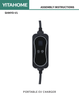
+ + + + + +
input output
L E N L E N
Starterbatterie
DC Sicherung
(so nah wie möglich
an den Batterien)
AC max. Schaltstrom
(Durchgang):
230V/50-60Hz
Max 16A AC (1600W)
110V/50-60Hz
Max 32A AC (1600W)
Schnell-Installation
Service-Batterien
+ + +
L E N
AC INPUT
(SHORE POWER)
+ + +
L E N
AC OUTPUT
( to consumer unit
with RCD )
DC – DC +
1
6
7
8
DC Ausgang AC Eingang ACHTUNG:
34
11
910 2
Alarm
(alarms on box )
Sicherung
10A
+ + + + + +
Eingang Ausgang
AC 230V
EINGANG
AC power out
AC 110V
power in
AC AUSGANG
L E N L E N
FI ( Fehlerstrom-
Schutzschalter)
Sicherungen sind hauptsächlich dazu da, die Kabel zu sichern,
nicht primär das Gerät.
L=Phase
E=Schutz-
leiter
N=Neutral
Arbeitet das Gerät im Wechselrichter-
Modus, dann wird der Neutral-Leiter mit
dem Schutzleiter verbunden, um die
Funktion des FI-Schalters zu
gewährleisten.
Optionaler
Ladeausgang
bis max. 5A
AC Cable 110V
12 AWG 3.5mmsq 30A
AC Kabel 230V
2,5mm² für 16A
DC Kabel und Sicherungen
NEG POS
5
12
4
2
3
LS-
Schalter
MODELL Sicherung Kabel ( 0 - 2,5m) Kabel (2,5 - 4m)
PCSP(A)121600 250A 50mm² 70mm²
PCSP(A)241600 150A 16mm² 35mm²
1) AC 230V/110V Eingang vom Netz. 7) Battery-Typ-Auswahl
2) Sicherung für Wechselrichter Ausgang 8) Optionaler Ladeausgang
3) AC 230V/110V Ausgang zum FI + Verteilung. 9) DC MINUS Batterie Anschluss
4) Rücksetzbare Sicherung (Durchgang) 10) DC Positiv Anschluss
5) Optionale Steckplatine für zweiten 5A Ausgang 11) Verpolungs-Indikator
6) Anschluss für Fernbedienung

15
14.5
14
13.5
13
12.5
12
11.5
11
10.5
100%
50%
0%
Zeit
V
O
L
T
Für 24V x 2
FLOAT 13.5 V
1
1
2
2
3
34
4
4 - Stufen Ladekennline (IUoUo)
Installationanleitung
Batterie - Profile
abc ( under DC plate )
d
DC Abdeckkappe AC Abdeckkappe
Zum Öffnen der Anschlüsse müssen die
Abdeckkappen entfernt werden.
Für den DC Anschluss schrauben Sie zuerst die
Schrauben a + b heraus und schieben Sie die
Kappe nach unten.
Für den 230V AC Anschluss schrauben Sie die
Schraube c + d heraus. Die Schraube c liegt
unter der DC Abdeckkappe. Um an die AC
Anschlüsse zu gelangen, muss zuerst die DC
Kappe entfernt werden.
++
+
+
4
S
T
R
O
M
Benötigte AC Leistung für das Ladegerät
Model 100% 50% 25%
1600 1300W 1000W N/A
Preset
Ladespannung
(V)
Erhaltungss
pannung (v)
0Nur für Fabrik N / A N / A
1Gel I 14.0 13.7
2AGM I 14.1 13.4
3AGM II 14.6 13.7
4Wartungsfrei 14.4 13.6
5LiFePO4 14.4 13.8
6Offene Blei-Säure 14.8 13.3
7Kalzium 15.1 13.6
8Desulfatierung 15.5V für 4 Std. N / A
9Ohne Funktion
x2 für 24V

Zusätzliche Informationen
4
2
5
Specification Table
WECHSELRICHTER 1600
Spannungsverlauf Reiner Sinus
Benötigter Eingangs-Spannungsverlauf Reiner Sinus
Nominale Eingangsspannung 110VAC | 230VAC
Eingangsspannungsbereich 95-130V | 196-245V
Dauerleistung VA (25 Deg C) 1600VA
Dauerleistung W (25 Deg C) 1300W
Dauerleistung W (40 Deg C) 1200W
Maximalleistung W 3000W
Energiesparmodus ja
Energiesparmodus aktiv < 20W Last
Stromverbrauch aktiv Modus (12V | 24V) 0.9A | 0.5A
Stromverbrauch im Energiesparmodus (12V | 24V) 0.4A | 0.2A
LADEGERÄT
Ladeleistung (12V | 24V) 70A | 40A
Optionaler Ladeausgang (12V | 24V) 4A
Batterie-Temperatur-Sensor Yes
ALLGEMEIN
Fernbedienung ja, Frontpanel
Leistung der Spannungsumschaltung 16A
Unterspannung +/- 4% (110V | 230V) <90V | <190V
Minimale Spannung +/- 4% (110V | 230V) >95V | >194V
Überspannung +/- 4% (110V | 230V) >125V | >263V
Reaktivierung nach ÜS +/- 4% (110V |230V) <123V | <243V
Maximale Eingangsspannung +/- 4% (110V | 230V) 130V | 270V
Frequenzeingang +/- 4% (110V | 230V) 60Hz | 50Hz
Unterfrequenz-Abschaltung +/- 4% (110V | 230V) <50Hz | <40Hz
Überfrequenz-Abschaltung +/- 4% (110V | 230V) >62Hz | >53Hz
Überlast-Schutz Sicherung
Verpolungsschutz (AC) Sicherung
Effizienz der Umschaltung 96%+
Umschaltzeit 20ms
Umschaltung ohne Batterie ja
Maximale Verbrauchslast der Durschschaltung 16A
Überlast-Schutz der Durchschaltung 20A Sicherung
WECHSELRICHTER SPEZIFIKATION
Leistungsfaktor 0.9-1.0
Nominale Effizienz 85%+
Maße und Gew ichte
Höhe x Breite x Tiefe (mm) 225 x 225 x 225 380 x 225 x 225 520 x 225 x 225
Gew icht (kg) 10 18 26

AC Input online, battery charger active
Power save OFF, inverter ON, charger OFF
Charger ON, fast charge mode (Flashing)
Charger ON, float charge mode
Unit over temperature trip
Inverter overload trip
Power save ON, inverter ON, charger OFF
Aux 12V output charger active
Aux 24V output charger active
WARNING- High Voltage cover plate side.
Do not remove unless qualified to do so.
To avoid electric shock,
disconnect AC power & DC battery power
before doing any work on this product
WARNING- Low Voltage high current cover plate side.
Do not open or remove any cover plates unless qualified
to do so. Read and fully understand all operation and
installation instructions regarding this product before
proceeding to install or use this product.
Pro Combi S+1600
www.sterling-power.com www.sterling-power-usa.com
Designed and developed in England. Made in Taiwan
1
2
3
4
5
6
7
8
9
LED Information + Spezifikation
LED Anzeige
Dauer - Alarmton
Alarmton alle 5 Sekunden
Fernbedienungs LEDs
Identischer Alarmton wie Gerät
Maximalstromladung
Ausgleichsladung
Erhaltungsladung
Standby
Wechselrichter EIN
Energiesparmodus AN
Unterspannung
Batterie - Überspannung
Überlast ( Wechselrichter)
Überlast (230V / 110V Netz)
Überhitzung (Wechselrichter)
Überhitzung (Netzmodus)
Überladung
Lüfter blockiert
Battery high V
Inverter mode overload
Line mode overload
Over temperature
Back voltage
F = Blinken
F
Power saver
auto mode
Power saver
off
Charge
only
on=
Charge on
Flash =
Charge only
Inverter
(Inverter on )
Alarm
(alarms on box)
1
2
3
Combined pure sine wave inverter and battery charger
Pro Combi S Plus
Landstrom anliegend, Ladegerät aktiv - 1
Energiespar AUS, Wechselr. EIN, Ladeg. AUS - 2
Ladegerät EIN, Ladung aktiv - 3
Ladegerät EIN, Erhaltungsladung - 4
Gerät überhitzt - 5
Wechselrichter überlastet - 6
Energiespar AN, Wechselrichter EIN, Ladeg. AUS - 7
2. Ladeausgang 12V aktiv - 8
2. Ladeausgang 24V aktiv - 9
LED Fehler Anzeigen
6

DC
Abdeckung
Power saver
auto mode
Power saver
off
Charge
only
on=
Charge on
Flash =
Charge only
Inverter
(Inverter on )
Alarm
(alarms on box)
1
2
3
Combined pure sine wave inverter and battery charger
Pro Combi S Plus
Installation der Fernbedienung
Schieben Sie die 2 Seitenteile zur Seite und
entfernen Sie die 4 Schrauben.
Anschließend können Sie das
Fernbedienpanel vorsichtig herausnehmen.
Achten Sie auf das Kabel an dem Panel.
Fernbedienung - 3 Funktionen
Bedienhinweis: Installieren Sie das Fernbedienpanel an der von Ihnen gewünschten
Position. Wenn Sie keinen Kühlschrank oder ähnliche Produkte nutzen, welche einen
ständigen Standby-/Autostart-Modus benötigen und jeder unnötige Stromverbrauch
verhindert werden soll, dann schalten Sie den Wechselrichter über das Panel aus,
wenn er nicht benötigt wird (Inverter off/ Charge only).
AC Input online, battery charger active
Power save OFF, inverter ON, charger OFF
Charger ON, fast charge mode (Flashing)
Charger ON, float charge mode
Unit over temperature trip
Inverter overload trip
Power save ON, inverter ON, charger OFF
Aux 12V output charger active
Aux 24V output charger active
Ext. Spannung am Eingang,
Gerät arbeitet als Ladegerät Keine ext. Spannung,
Wechselrichter EIN
Stromsparmodus EIN
~0,4A (12V) Stromverbrauch
Keine ext. Spannung,
Wechselrichter EIN
Stromsparmodus AUS
~0,9A (12V) Stromverbrauch
*
**
*
**
Leuchtet, wenn der optionale 12V
Ladeausgang installiert ist.
Leuchtet, wenn der optionale 24V
Ladeausgang installiert ist.
4
2
7

Sterling Power Products
Copyright
Wartung, Pflege & Garantie
STERLI G
POWER
8
Regelmäßige Überprüfungen vor dem Einschalten
ŸAuf Beschädigungen.Sollte das Gerät beschädigt
sein, darf es nicht weiter betrieben werden. Es sind
dann alle stromführenden Kabel zu entfernen.
ŸAuf Gegenstände, die die Lüftung des Gerätes
abdecken oder beeinträchtigen könnten.
ŸAuf Verschmutzungen der Lüftungsein- und auslässe.
Sollten Verschmutzungen bestehen, müssen diese
vor der Inbetriebnahme entfernt werden.
ŸSicherungen auf Kontakt und Korrosion
ŸAuf Feuchtigkeit oder Wassereintritt
Regelmäßige Überprüfungen nach dem Einschalten
ŸAuf korrekte Funktion und Ladung
ŸAuf Fehlermeldungen/-anzeigen
Monatliche Überprüfungen
ŸFeste Verbindung des Gerätes mit der Wand /
Befestigungswand bestätigen.
ŸAlle Anschlüsse am Gerät fest sind und keine Kabel
lose herumhängen.
ŸKorrosion von Anschlüssen und Kabeln.
ŸKabelzustand und Befestigung
ŸBatteriezustand und Kontrolle des Wasserstandes bei
offenen Blei-Säure-Batterien
ŸBatterietemperatur während des Ladevorganges.
Diese darf nicht viel höher sein, als die
Umgebungstemperatur.
Fehlerbehebung und Reparatur
Sollte es zu einer Fehler am Gerät kommen, sollte zuerst
übeprüft werden, um welchen Fehler es sich handelt und
ob es Möglichkeiten gibt (solange des sich um einen
Fehler handelt, der außerhalb des Ladegerätes die
Ursache hat), diesen zu beheben.
Im Zweifelsfall rufen Sie bitte unsere Service-Nummer
an, die Sie bei Ihrem Händler oder auf unserer Webseite
erfahren.
Grundsätzlich sollte immer überprüft werden, ob alle
Kabel korrekt verbunden sind und ob alle Sicherungen
funktionieren und nicht durchgebrannt sind. Auch
Korrosion kann erheblichen Einfluss auf den Stromfluss
haben.
Ein- und Ausschalten des Gerätes, mit einer Pause von
mindestens 10 Sekunden (komplett stromlos machen)
kann auch zu einer Fehlerbehebung führen, sollte sich
die Software aufgehängt haben.
Sollte der Fehler weiter bestehen, ist als nächstes der
Temperatursensor zu entfernen, um festzustellen, ob
dieser Sensor eventuell defekt ist.
Auch sind alle Ausgänge mit einem Multimeter zu
überprüfen, um festzustellen, ob die angezeigten
Spannungen mit den Messungen des Multimeters
übereinstimmen.
Überprüfen Sie alle verbauten Sicherungen auf
einwandfreie Funktion und Durchgang.
Auch gibt es Fehler, welche nicht auf einen Fehler des
Gerätes zurückzuführen sind.
Eine zu hohe Spannung „DC high voltage trip“ kann auch
durch eine externe Spannungsquelle verursacht werden.
Der Fehler „High Charger Temp trip“ kann auch deshalb
vorkommen, weil das Gerät in einer zu warmen
Umgebung installiert wurde, kein Luftaustausch
vorhanden ist oder der Lüfter defekt ist.
Der Fehler „Unterspannung“ kann auch dadurch
zustande kommen, dass die Batterien defekt oder
sulfatiert sind, und keine Ladung mehr aufnehmen und
abgeben können.
Versuchen Sie NIEMALS das Gerät selber zu
reparieren oder zu öffnen.
Senden Sie ein defektes Gerät an uns oder Ihren
Händler mit einer Fehlerbeschreibung und einer
Kopier der Kaufrechnung zurück.
Unsere Adresse:
Sterling Power Products Ltd.
8 Wassage Way
GB - Droitwich WR9 0NX
UK / England
Tel: +44 1905 771 771
email: deutsch@sterling-power.com
help@sterling-power.com
Bitte überprüfen Sie vor Rücksendung an uns, ob die
Adresse und Kontaktdaten noch aktuell sind.
Alle Sterling Produkte haben eine 2 Jahre Werksgarantie
Kontaktieren Sie Sterling in Europa oder den USA.
8
/