Page is loading ...

Installation and Operating Manual
MobilPOWER Inverter SMI 1200 Sinus ST No. 3177
MobilPOWER Inverter SMI 1700 Sinus ST No. 3183
Inverter 12 V DC / 230 V AC for application in special purpose vehicles, high-quality campers, as well
as in the marine field.
The sine inverters convert 12 V Direct Voltage (DC) of a battery into
230 V/50 Hz Sinusoidal Alternating Voltage (AC) in quality of mains voltage.
The MobilPOWER Inverters Sinus are the ideal solution for operation of all 230 V mains consumers with high power
consumption of up to 1200/1700 Watts continuous rating, such as air-conditioning systems, electric tools, cleaning
appliances, coffee makers, microwave ovens, vacuum cleaners, hair driers etc.
On the other hand, also sensitive units with low capacity, such as computers, laptops, fax units, printers, scanners,
wireless transmitting sets, small charging devices, charging trays, monitors, TV, video etc., can be operated without any
problems.
This list comprises also appliances with electronic control and complex power control, such as automatic coffee machines,
as well as low-cost units with simple capacitor power packs.
The units are designed according to the state of the art in clock pulse-controlled execution (“switch mode”). Due to the
microprocessor control combined with advanced SMD technology a compact design could be realized. Easily running fans
(with speed control) being noise-optimised and friction-optimised ensure perfect cooling and thus unproblematic
continuous operation, even at full capacity.
Furthermore, the thermal and electric load, as well as overload and short-circuit of the output circuit are supervised by
integrated protective circuits.
The inverters are equipped with an intelligent control for power saving with automatic disconnection, which ensures
minimised power consumption during idle time.
An integrated undervoltage protection protects the batteries by disconnecting the inverter in case of dropped battery
voltage.
Features:
• Output voltage in quality of mains voltage (pure sine)
• Output frequency crystal stabilized
• Control for power saving with automatic disconnection (automatic mode)
• The display panel can be rotated by 360 °, and it can be used as remote control.
• Solid dimensioning, robust and compact design, high operating safety.
• Automatic disconnection in case of low voltage of the battery
• Automatic disconnection in case of overvoltage of the battery
• Electronic and thermal overload protection
• Intelligent microprocessor control
• Clock-pulse controlled execution (switch mode)
• High efficiency (approx. 90 %)
• Continuous cooling fan with temperature control and control of the fan-in current
Please read these assembly and operating instructions and in particular the safety instructions on
page 2 before starting the connection and start-up.

- 2 -
Safety Instructions
Appropriate Application:
The inverter has been designed according to the valid safety regulations.
Appropriate application is restricted to:
1. At lead acid, gel or AGM batteries as well as LiFePO4 batteries of the specified rated voltage in fixed
installed systems. The specified minimum battery capacity must be observed.
2. For supplying mains voltage devices up to the specified maximum power.
3. With battery connection cable of the recommended minimum cross-section and maximum length.
4. Technically faultless condition.
5. Installation in rooms being protected from rain, humidity, dust, aggressive battery gas, as well as in an
environment being free from condensation water.
6. If the driver and other road users are not affected.
• Never use the unit at locations where the risk of gas or dust explosion exists!
• The inverter is to be equipped with a fuse for protection of the battery cables.
• Open-air operation of the unit is not allowed. For installation in vehicles the valid VDE safety regulations are to
be observed!
• Handling of units being connected to the inverter is to be effected as careful, as if the units were connected to
the local mains supply. In case of potential hazardous situations, the inverter is to be switched-off immediately,
or the consumer is to be separated from the inverter.
• Never open units being connected to the inverter, neither when the inverter has been switched-off, nor when
it is separated from the battery.
• Never connect supply voltage, an AC generator or an additional inverter to the socket of the inverter,
otherwise the unit might be destroyed.
• Cables are always to be laid in such a way that damage is excluded. Observe to fasten them tightly.
• Do not lay the 12 V cable with 230 v cables together in the same cable duct (conduit).
• Check live cables or leads periodically for insulation faults, points of break or loosened connections. Occurring
defects must be remedied immediately.
• The unit is to be disconnected from any connection prior to execution of electrically welding or work on the
electric system.
• If the non-commercial end-user is not able to recognize the characteristic values being valid for a unit or the
regulations to be observed, a specialist is always to be consulted.
• The user/buyer is obliged to observe any construction and safety regulations.
• Do not open the unit in any way! It contains no user-replaceable parts and can also contain dangerously high
voltages for a long time (especially in case of faults) after separation from the battery)!
• Keep children away from the inverter and the batteries.
• Observe the safety regulations of the battery manufacturer.
• Non-observance may result in injury or material damage.
• The warranty period is 36 months from the purchase date (against presentation of the sales slip or invoice).
The warranty will be void in case of any inappropriate utilisation of the unit, if it is used beyond the technical
specification, in case of improper operation or external intervention. We do not assume any liability for any
damage resulting hereof. The liability exclusion is extended to any service being executed by third, which has
not been ordered by us in writing. Service is to be effected exclusively by VOTRONIC Lauterbach.
Installation:
Install the inverter near the battery/batteries (to enable short battery cables) at a location being clean and protected
from humidity. The unit can be installed in any position. The vent holes should never be covered (distance to the vent
holes and air escape at the front and at the back: at least 20 cm) to ensure optimum cooling. If the inverter is installed in a
storage space, the storage space must be equipped with a sufficient number of vent holes to ensure sufficient ventilation
to the ambiance. Install the unit on an even and hard mounting surface. The four rubber feet are provided for reduction
of vibration. Never remove the rubber feet.

- 3 -
Display Panel / Remote Control:
The display panel can be removed after removal of the two fastening screws to
facilitate positioning of the inverter. It can be reinstalled later in the desired position
(it can be rotated in steps by 90 °) and screwed down.
If the inverter had been installed at a difficultly accessible location, the display panel
can also be used as remote control. Remove the display panel from the unit, reconnect it
to the unit using the control cable (length 5 m) and install it at the desired location.
Capacity of the Battery (Ah):
Ensure that sufficient battery capacity is available to achieve optimum operation of the inverter. If a small consumer, such
as a TV-set (approx. 50 Watts) is operated over the inverter, the load of the battery is only approx. 5 amperes. This
means, that a battery capacity of e. g. 100 Ah allows an operation of many hours without any problems.
However, should the inverter load be approx. 1000 watts (hair dryer, vacuum cleaner etc.), the current rate is many times
higher (approx. 100 amperes), and the operating time with the same battery capacity (100 Ah) is reduced to approx. 15 -
30 minutes. This means, a small battery capacity reduces the operating time of large consumers significantly.
Connection to the Battery:
The connection of the battery cable for the inverter (2x25 mm² or 35 mm²) should always be made with
CORRECT POLARITY! Wrong polarity might result in destruction of the unit!
A unit failure due to wrong polarity will be recognized and stored. This can be recognized in the factory at
any time. This improper operation is not covered by the guarantee.
Black Cable: - Negative Pole (Ground) to the negative pole of the battery (or Shunt of Batt.-Computer)
Red Cable: + Positive Pole (+12 V) over a fuse to the positive pole of the battery (cable protection)
Table 1: Recommended Length of Battery Cable, Cross-section and + Fuse:
Length of Battery Cable
Plus + (red) and
Minus – (black)
SMI 1200 Sinus ST SMI 1700 Sinus ST
red and black each 0.8 - 2.0 m 25 mm2 ** 35 mm2 **
red and black each 2.0 - 2.8 m 35 mm2 50 mm2
Fuse into +-cable 175 A 250 A
** The stated value indicates also the required minimum cross section on the unit performance!
When connecting the inverter to the battery, a spark might occur for a short moment. Therefore, ensure
sufficient ventilation during connection (explosive battery gas)!
It is highly recommended to insert the fuses between the battery and the inverter into the positive cable near the battery
to avoid fire at the cables. Fuse holder with short connection cable and fuses are available as accessories (see available
accessories).
Connection Output Alternating Voltage (AC):
Observe the extremely dangerous supply voltage 230 V AC at the output of the inverter at the shockproof
socket! Always observe the national installation regulations and the safety regulations concerning
protection from electric shocks (protection against contact of live parts, insulation regulations).
Note: For reasons of safety and to avoid insulation faults of the connected units, as well as for universal
applicability, the output (230 V AC) of the inverter is designed in such a way, that it is electrically isolated
(completely isolated) from the battery side (DC) as well as from the housing. This means, it is neither earthed
to phase nor to zero internally (protection class II).

- 4 -
During the stand-by mode, the inverter is not completely switched-off, but it will be "searching" from
time to time!!
When being set to Run Mode "Always On", the inverter can start automatically!!
It is therefore imperative to always separate the inverter from the 230 V consumers or the installation
prior to execution of work at the 230 V consumers or the installation belonging to it (withdraw all plugs)!
Ensure, that no external voltage reaches the output "Out" of the inverter. Otherwise the unit might be
destroyed immediately.
Connection Plan 1:
Operation of one Consumer at the Inverter:
The consumer will be connected at the shockproof socket "OUT" of the unit.

- 5 -
Connection Plan 2:
Operation of a Multi-Socket at the Inverter:
The multi-socket will be connected at the shockproof socket "OUT" of the unit. According to standards, the multi-socket
should not be fixed installed, and the connection of the earth bolt at the inverter with the potential equalization cable 4
mm² green/yellow to the main earth terminal of the vehicle serves as protection from possible insulation faults of the
connected units.

- 6 -
Connection Plan 3:
Operation of Several Consumers in Fixed Installed System at the Inverter:
The fixed installed consumer sockets "2" are connected to the shockproof socket "OUT" of the inverter and, according to
standards, is led over a fault current breaker (FI, 30 mA) and is equipped with an additional potential equalization cable.
Furthermore, the terminal screws "N1" and "PE" at the inverter will be connected with a short insulated piece of wire 2.5
mm² serving as "earth bridge", and the earth bolt and the potential equalization cable 4 mm² green/yellow will be
connected to the main earth terminal of the vehicle.

- 7 -
Start-up and Operation:
After the connection of the inverter to the 12 V battery, the inverter is ready for operation.
The unit is switched-on by momentarily pressing the ON/OFF switch (ON) at the display panel of the inverter (ON). The
green light-emitting diode (LED) „INVERTER“ indicates the readiness for service. After an internal self-test of the entire
system being indicated by 2 short beeps and one long beep, the inverter operation starts. 230 V alternating voltage (AC) is
now supplied to the unit socket at the front panel for supply of the consumers.
Operation of the Inverter in Automatic Mode (Stand-by Mode):
The automatic mode helps to save battery energy in case of larger consumers. Very often, large consumers are switched-
on for a short moment or in intervals due to their high power consumption, but the inverter permanently loads the
battery, even if the consumer has already been switched-off (idle time)!!
This unnecessary battery load can be reduced by use of the stand-by function!
The inverter is started in automatic mode by momentarily pressing the ON/OFF switch, and the LEDs "INVERTER" and
"AUTOM." will be lighting.
When being switched-on, the inverter checks the connected load continuously (e. g. TV-set). So, capacity is required, as
long as the TV-set is switched-on (> 25 W, see below Adjustment of the Threshold). If the TV-set will be switched-off (< 25
W), the inverter will recognize this state, and it changes automatically to stand-by mode after a short observation time.
All light-emitting diodes will stop lighting, only the yellow LED „AUTOM.“ will be flashing every second. Now, the battery
load is reduced to approx. 0.4 A.
The inverter checks every second, if any load (> 25 W) has been
connected to the output. If the inverter does not find a consumer
within the following 5 or 10 minutes (duration of the search is
adjustable) during the stand-by mode, it will be switched-off
completely, and it can only be restarted by means of the ON/OFF
switch (safety measure).
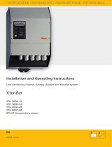
Optimum adaptation of the stand-by mode to the corresponding
requirements is achieved by setting the stand-by threshold (load) as
well as the duration of the stand-by search (time). Remove the
display panel from the front panel and use the two switches for
setting:
Switch 1 (Load): Threshold 25 W or 60 W
Switch 2 (Time): Duration of the search, 5 minutes or 10 minutes
Switch 3 (PowerSave): If desired by remote control
can be switched-on/off or permanently off
Switch 4 (Run Mode): Operation by display panel / remote control or
continuous operation
During the stand-by mode, the inverter is not completely switched-off!!
When being set to Run Mode "Always On", the inverter can start automatically!!!
It is therefore imperative to always separate the inverter from the 230 V consumers or the
installation prior to execution of work at the 230 V consumers or the installation belonging to it!
View: Display panel removed

- 8 -
Operation of the Inverter without Automatic Mode (Stand-by Mode = OFF):
If the inverter shall be operated without automatic mode, which might be required for unproblematic operation of
consumers with very low capacity, such as battery chargers, portable radios etc., the automatic mode must be
deactivated.
This can be effected in two different ways.
1. Permanent Setting:
Set switch 3 (PowerSave) to position OFF.
2. Setting can be selected when starting the inverter:
Push the ON/OFF switch for more than 3 seconds when starting the inverter. After this time, the yellow LED
„AUTOM.“ will stop lighting, and the inverter is in continuous mode.
If the connected consumer is switched-off, the inverter will continue working (idle time), and it will load the
battery permanently with approx. 7-10 watts!
Operation of the Inverter in Permanent Continuous Operation:
If the inverter shall operate in permanent continuous operation, set switch 4 (RunMode) to position "Always ON".
This switch position starts the inverter automatically as soon as it is connected to 12 V battery voltage.
During this mode the key of the display panel has no function. Operation of the inverter can be reactivated by
setting switch 4.
Connected Capacity of the Connected Consumers:
A safe operation requires, that the total of the nominal capacity rates (Watts) of the connected consumers (indication in
"VA” or "W" on the nameplate or in the technical data of the corresponding appliance) does not exceed the nominal
capacity of the inverter (1200 / 1700 W).
Please observe, that the real current consumption of many 230 V household appliances is higher than the value resulting
from the active power, which is indicated in "W" on the nameplate.
It is also to be considered that almost all appliances are requiring a higher capacity during the starting phase (moment of
starting) than during normal operation. The starting capacity can be many times higher than the continuous rating! For
these appliances, the inverter can be loaded above its nominal capacity for a short-moment (refer to technical data).
Pilot Lamps Load/Overload and Overload Protection:
The load of the inverter is indicated by three light-emitting diodes (LED) at the control panel:
• The LED „< 50%“ is lighting in green, if the load is approx. 10 / 20 Watts up to 50 % of the nominal capacity of the
connected appliance.
• If the nominal capacity exceeds 50 %, the LED „<100 %“ will be lighting in yellow.
• If the inverter is operated with more than 100 % of its nominal capacity, the red LED „OVERLOAD“ will be lighting.
Additionally, an audible alarm will refer to the overload.
From an overload of 5 %, the rhythm of the audible alarm will be slow. During this operating state, the inverter
will continue working; however, a disconnection of the inverter due to overtemperature can be expected in the
long term.
From an overload of 15 %, the rhythm of the audible alarm will be quick. In case of this operating state, the
inverter will be disconnected within the following 10 seconds. Now, the drawn capacity should immediately be
reduced.
If the maximum duration for the overload is exceeded, the inverter will be switched-off due to overload. The green LED
„INVERTER“ will stop lighting, the red LED „OVERLOAD“ will be flashing, and an audible signal is released. After reduction
of the connected load or disconnection of consumers, the inverter can be restarted by pushing the ON/OFF switch.

- 9 -
Table Error Messages:
If the inverter is switched-off due to overload, this disconnection is additionally evaluated to describe the error
clearly. The LED display indicates the criterion for disconnection as below:
(X = LED is flashing, O = LED is flashing depending on time and temperature, = LED OFF):
Overload
< 100 %
< 50 %
Inverter
Type of Load
Audible Signal
X
X
X
- / O
A) Output bridge defective
Beep for 3 sec. - Pause
X
X
-
- / O
B) Short-circuit output
2x Short Beeps - 1x Long Beep - Pause
X
-
-
- / O
C) Overload, Load Jump
6 x Beep - Pause
X
-
-
- / O
D) Overtemperature
8 x Beep - Pause
-
-
-
- / O
E) Undervoltage
4 x Beep - Pause
-
-
-
- / O
F) Overvoltage
2 x Beep - Pause
-
-
-
X
G) Internal Error
Beep Interval without Pause
Error Messages:
A) The inverter has recognized a component failure. As long as the LED „INVERTER“ is flashing (approx. 1 minute),
the inverter has not been cooled down sufficiently to be restarted. Switch-off all connected consumers and
restart the unit. If the failure should be indicated several times (3x), the inverter is defective. In this case, please
contact our service address.
B) The inverter has recognized a short-circuit or an operating state being similar to a short-circuit. (This might have
been caused by connection of a consumer with very high starting current rates, and does not necessarily stand
for a defective 230 V consumer). As long as the LED „INVERTER“ is flashing (approx. 1 minute), the inverter has
not been cooled down sufficiently to be restarted. Switch-off all connected consumers and restart the unit. In
this case, it should be observed to switch-on the consumers in the lowest power stage to ensure safe starting of
the appliance. Increase the capacity step by step after that (e. g. vacuum cleaner). A possibility to start
appliances with high starting current is to "run up" the inverter together with the consumer. First switch-on the
corresponding consumer and after that the inverter. By this method, the inverter limits the maximum capacity of
the consumer during starting.
If the failure should be indicated at least 3 times, the inverter is defective and must be checked in the factory.
C) The inverter has recognized an excessive load or load jump. Load jumps or high starting current rates are always
an extreme load for the inverter. In order to prevent damage of the inverter by these characteristics, the inverter
being already heated by load will be switched-off earlier than an inverter being cold. As long as the LED
„INVERTER“ is flashing, the inverter has not been cooled down sufficiently to be restarted.
D) A further measure for protection against continuous overload or insufficient cooling (see installation) is the
internal temperature control (protection against overheating) for automatic disconnection of the inverter. An
audible signal can be heard, the green LED „INVERTER“ will stop lighting, and the red LED „OVERLOAD“ will be
flashing. The integrated cooling fan continues working. Permanent lighting of the red LED „OVERLOAD“ during
operation indicates a premature disconnection of the inverter. Increased temperature is indicated by a slow
beep rhythm.
Further increase of the temperature will be indicated by a quick beep rhythm, and the inverter will be switched-
off.
Restart the unit by pushing the "ON/OFF" switch. If this should not be possible, restart it after a longer cooling-
down phase.
E) The battery is controlled by the inverter to prevent harmful total discharge of the battery.
1. In case of dropped battery voltage, an audible signal (4x "Beep") indicates imminent total discharge.
2. In case of a discharged battery, an additional audible signal (4 x „Beep“) indicates imminent total discharge,
and the inverter will be switched-off automatically.
The inverter determines the switching thresholds dynamically from the battery load.
F) The inverter protects itself against excessive battery voltage (>15 V) by automatic disconnection: The green LED
„INVERTER“ will be flashing, and an audible signal (2 x „Beep“ ) can be heard.
G) The self-test of the inverter has recognized an internal error or a condition beyond the limit values. Starting is
not possible to prevent destruction of the inverter. The green LED „INVERTER“ will be flashing, and an audible
signal (continuous „Beep“ interval) can be heard. In case of this failure, the unit can be restarted after approx.
10-15 minutes waiting time.
If the failure occurs frequently, please contact the service address.

- 10 -
Tips for Inverter Operation:
• The inverter itself only requires few current. Thus, the connected consumers determine the current consumption
out of the battery. The longest possible operating time at the battery can be achieved by disconnection of the
consumers being not required.
• If possible, the automatic mode (stand-by function) should be used to save energy.
• The real power consumption of some consumers, such as TV-sets being set to a very high brightness, is higher
than the indicated nominal capacity.
• The power requirement of HiFi-systems with inferior volume is comparatively much lower than the indicated
capacity.
• The power consumption for starting of some consumers is higher than during the continuous operation. If the
continuous rating of these consumers is e. g. below 25 W, but the starting capacity exceeds 25 W, it might
happen that these consumers are continuously switched-on and off during the automatic mode (stand-by
function). In this case, the automatic mode should be deactivated, and the inverter should be switched-off
manually after use.
• Operation of 230 V consumers only during driving or with running motor is possible by an ON/OFF control unit
(control unit, order No. 2065) being available as accessory switching the inverter automatically on and off over
the D+ of the dynamo.
• Operation of the inverter with a second display panel or a second remote control is possible with an extension
set with control cable of 5 m length, adapter and remote control being available as accessory (order No. 2067).

- 11 -
Technical Data:
Technical Data: SMI 1200 Sinus ST SMI 1700 Sinus ST
Nominal Voltage Lead-Acid/Gel/AGM Battery (DC): 12 V 12 V
Nominal Voltage Lithium LiFePO4 Battery (DC): 12 V - 13.3 V 12 V - 13.3 V
Input Voltage (DC): (10.5 V - 15.5 V) (10.5 V - 15.5 V)
Recommended Minimum Battery Capacity: > 110 Ah (depending on consumer) > 150 Ah (depending on consumer)
Battery Connection Cable min. Cross-Section: 25 mm2 35 mm2
Battery Connection Terminals Clamping Range: 50 mm2 50 mm2
Recommended Fuse Positive Pole Battery: 175 A 250 A
Output Voltage (AC): 230 V Pure Sine 230 V Pure Sine
Output Frequency: 50 Hz, crystal stabilized 50 Hz, crystal stabilized
Continuous Rating (at 40 °C / 12.0 V): 1200 W 1700 W
Momentary Capacity: 1400 W 2100 W
Peak Power: 2000 W 3000 W
Power Consumption DC at Nominal Capacity: 115 A 165 A
Power Consumption DC at Overload max.: 150 A 210 A
CosPhi of the Consumers: No Restriction No Restriction
Overvoltage Battery max.: 16.0 V 16.0 V
Low Voltage Battery min.: 10.5 V (load-dependent, dynam.) 10.5 V (load-dependent, dynam.)
Own Consumption ON (without load) approx.: 8 W 10 W
Own Consump. During Stand-by (without load): approx. 3 W approx. 5 W
Criterion for Disconnection of Stand-by: < 25 W / 60 W < 25 W / 60 W
Dwell Time for Stand-by: 30 Seconds 30 Seconds
Duration During Stand-by: 5/10 Minutes 5/10 Minutes
Overload Protection /Overtemperature Protect.: Yes / Yes Yes / Yes
Fan with Continuous Temp. Control: Yes Yes
System of Protection, Protection Classes: IP2X, II IP2X, II
Dimensions (mm): 366 x 262 x 91 482 x 262 x 92
Weight: 3,800 g 4,900 g
Ambient Conditions, Humidity of Air: max. 95 % RH, no condensation
Safety Regulations: EN 62368-1

- 12 -
Declaration of Conformity:
In accordance with the provisions of the statutory requirements and the relevant directives, Electrical
Equipment (Safety) Regulations 2016, Electromagnetic Compatibility Regulations 2016, The Restriction of
the Use of Certain Hazardous Substances in Electrical and Electronic Equipment Regulations 2012 this
product complies with the following standards or normative documents:
BS EN55014-1; BS EN61000-6-1; BS EN61000-4-2; BS EN61000-4-3; BS EN61000-4-4; BS EN62368-1;
BS EN50498, BS EN IEC 63000.
Declaration of Conformity:
In accordance with the provisions of Directives 2014/35/EU, 2014/30/EU, 2009/19/EC, this
product complies with the following standards or normative documents:
EN55014-1; EN55022 B; EN61000-6-1; EN61000-4-2; EN61000-4-3; EN61000-4-4;
EN61000-4-5; EN62368-1; EN50498.
The product
must not be
disposed of in
the household
waste.
The product is RoHS compliant.
It complies with the directive
2015/863/EU for Reduction of
Hazardous Substances in electrical
and electronic equipment.
Recycling:
At the end of its useful life, you can send us this device for professional disposal:
You can find more information about this on our website at www.votronic.de/recycling
Delivery Scope: Available Accessories:
•
Power Inverter - Control Unit Order No. 2065
•
IEC Power Cable, Length: 2 m - Extension Set with Second Remote Control Order No. 2067
•
Installation and Operating Manual - Power fuse holder Order No. 2250
• Control Cable, 5 m Length, for
Operation of the Display Panel as
Remote Control
for SMI 1200 Sinus ST:
- High-current cable 25 mm², length: 40 cm, for
fuse holder
Order No. 2262
- Power Fuse 175 A
Order No. 2256
for SMI 1700 Sinus ST:
- High-current cable 35 mm², length: 40 cm, for fuse
holder
Order No. 2263
- Power Fuse 250 A
Order No. 2259
Subject to misprints, errors and technical modification without notice.
All rights reserved. This material may not be published, broadcast, rewritten or redistributed in whole or part without the
express written consent of the manufacturer. Copyright VOTRONIC 11/2022.
Made in Germany by VOTRONIC Elektronik-Systeme GmbH, Johann-Friedrich-Diehm-Str. 2, 36341 Lauterbach/GERMANY
Phone: +49 (0)6641/91173-0 Fax: +49 (0)6641/91173-10 E-mail: [email protected] Internet: www.votronic.de
/