Page is loading ...

QTS-CLX-APACS
APACS
®
IOBUS Module
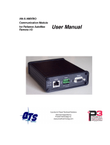
User Manual

Page ii QTS-CLX-APACS March 2015
Because of the variety of uses for the products described in this publication, those
responsible for the application and use of these products must satisfy themselves that all
necessary steps have been taken to assure that each application and use meets all
performance and safety requirements, including any applicable laws, regulations, codes
and standards. In no event will Quest Technical Solutions be responsible or liable for
indirect or consequential damage resulting from the use or application of these products.
Any illustrations, charts, sample programs, and layout examples shown in this publication
are intended solely for purposes of example. Since there are many variables and
requirements associated with any particular installation, Quest Technical Solutions does
not assume responsibility or liability (to include intellectual property liability) for actual
use based upon the examples shown in this publication.
Throughout this manual we use notes to make you aware of safety considerations.
WARNING!
Identifies information about practices or circumstances that can lead to
personal injury or death, property damage, or economic loss.
These warnings help to:
• identify a hazard
• avoid the hazard
• recognize the consequences
IMPORTANT!
Identifies information that is especially important for successful
application and understanding of the product.
TIP
Identifies information that explains the best way to use the
QTS-CLX-APACS
Microsoft is a registered trademark of Microsoft Corporation.
Windows, Windows 95, Windows NT, Windows 2000, Windows XP and Vista are trademarks of Microsoft Corporation.
ControlLogix, RSLinx and RSLogix 5000 are trademarks of the Allen-Bradley Company, Inc.
APACS and 4-mation are trademarks of Siemens Moore Process Automation, Inc.


QTS-CLX-APACS MODULE OVERVIEW 1
Part Number 2
Module Features 2
Power Requirements 3
Other Requirements 3
Package Contents 3
INSTALLATION 4
Prevent Electrostatic Discharge 4
Prepare the Chassis for Module Installation 4
Determine Module Slot Location 4
Insert the Module in the Chassis 5
Replacing a Module 6
Cabling and Termination 7
Software Installation 7
CONFIGURING THE MODULE IN RSLOGIX 5000 8
Module Configuration 8
Adding the Module 8
RSLINX 14
MONITOR MODE OPERATION 15
ClxApacsMonCfg Software 15
Exporting a 4-mation database file 16
Configuring the IOBUS 16
Assigning ControlLogix addresses 17
What gets mapped 18
Setting the Module Name 19

QTS-CLX-APACS Page iii
Saving a Configuration File 21
Uploading and Downloading Configurations 21
Configuring the QTS-CLX-APACS Module in RSLogix 5000. 22
Aliases 22
Opening a Configuration File 24
Clearing the Configuration 24
Setting the RSLinx Path 24
Changing the Module Mode 24
USING MONITOR MODE FOR MIGRATION 25
MASTER MODE OPERATION 27
ClxApacsMasCfg Software 28
Configuring from an APACS IOBUS 28
Assigning ControlLogix addresses 30
What gets mapped 30
Setting the Module Name 32
Saving a Configuration File 33
Uploading and Downloading Configurations 33
Configuring the QTS-CLX-APACS Module in RSLogix 5000. 34
Aliases 35
Opening a Configuration File 37
Clearing the Configuration 37
Setting the RSLinx Path 37
Changing the Module Mode 37
ACCESSING DATA 38
Required Connections 38
I/O Data 38

Page iv QTS-CLX-APACS March 2015
Program/Run 38
Diagnostic Data 38
TROUBLESHOOTING 40
ControlLogix Module LEDs 40
NET LED – IOBUS Status 40
CLX LED – ControlBus Status 40
OK LED – Module Health 41
All LEDs Red 41
QTS-CLX-APACS Module 4-Character Display 41
RSLogix 5000 41
The Debug Log 42
Diagnostic Counters 42
Slot Status Bits 42
Fatal Errors 43
UPDATING THE FIRMWARE 44
SPECIFICATIONS 45
QTS-CLX-APACS ControlLogix Module 45
SUPPORT 46
WARRANTY 47

QTS-CLX-APACS Module Overview
The QTS-CLX-APACS connects a ControlLogix controller to an APACS
®
IOBUS
network.
Use the QTS-CLX-APACS to migrate APACS systems to ControlLogix controllers. You
can retain the APACS I/O as the first step in the migration.
The module acts as either a monitor or as a master on the APACS IOBUS. You select the
mode by downloading different firmware to the module, using the Windows configuration
programs provided.
In monitor mode, the QTS-CLX-APACS sends APACS I/O input and output data to input
data in the ControlLogix. It cannot transmit on the bus.
In master mode, the ControlLogix sends output data to the QTS-CLX-APACS, which then
transmits it as output data on the APACS IOBUS. The QTS-CLX-APACS sends APACS
input data to input data in the ControlLogix.
The QTS-CLX-APACS:
• supports IOBUS cable redundancy
• supports up to the maximum of 39 I/O cards allowed by the APACS IOBUS in a
maximum of 4 MODULRACS
The QTS-CLX-APACS communicates with the ControlLogix processor using scheduled
connections. You configure the module in RSLogix 5000 (v19 or greater) with up to:
• 10 I/O connections, 9 for data and 1 for status

Page 2 QTS-CLX-APACS March 2015
Each I/O connection supports:
• scheduled input data, 496 SINTs or 124 REALs
• scheduled output data, 496 SINTs or 124 REALs
The Windows configuration programs supplied with the module map IOBUS data to the
scheduled data. They also:
• upload and download configuration data
• map the IOBUS data to ControlLogix scheduled data
• save and open configuration files
• export aliases for use in your RSLogix 5000 application
• change the module mode, between monitor and master modes
Firmware Update
The module firmware can be updated using the Change Module Mode functions in the
Windows utilities supplied (see page 44).
Part Number
The part number of the module is QTS-CLX-APACS.
Module Features
The following figure shows the features of the module.
The module has:
• A label that identifies the module, text QTS
Universal Comm
• A 4-character scrolling display
• 3 LEDs, labelled NET, CLX, and OK, to indicate
the status of the I/O bus, the state of the connection
to the ControlLogix processor, and the internal state
of the module
• 2 5-pin Phoenix connectors to connect to the IOBUS
A and IOBUS B bus cables
The module supports insertion and removal under power.
The module is shipped in monitor mode, with a blank configuration.

QTS-CLX-APACS Page 3
Watchdog and Jabber Inhibit
A watchdog timer is implemented in the module’s hardware. If the firmware does not
kick the watchdog within the timeout period the watchdog times out and generates a fatal
error (see page 43) with error code D1. In master mode, the module stops scanning and
stops communicating with the ControlLogix.
A jabber inhibit timer is implemented in the module’s hardware. If the bus transmitter is
on longer than 150% of the longest frame time, the jabber inhibit forces the transmitter
off and generates a fatal error (see page 43) with error code D0. In master mode, the
module stops scanning and stops communicating with the ControlLogix.
Power Requirements
The QTS-CLX-APACS module requires 5 mA @ 24VDC and 475 mA @ 5.1VDC from
I/O chassis backplane.
Other Requirements
To use the Windows utility programs, you must have RSLinx software, version 2.54 or
later, with an activation. Use RSLinx Gateway or RSLinx Professional software. Do not
use RSLinx Lite.
Package Contents
• QTS-CLX-APACS module
• CD containing software and documentation

Page 4 QTS-CLX-APACS March 2015
Installation
Prevent Electrostatic Discharge
The module is sensitive to electrostatic discharge.
WARNING!
ATTENTION: Electrostatic discharge can damage integrated circuits
or semiconductors if you touch backplane connector pins. Follow these
guidelines when you handle the module:
• Touch a grounded object to discharge static potential
• Wear an approved wrist-strap grounding device
• Do not touch the backplane connector or connector pins
• Do not touch circuit components inside the module
• If available, use a static-safe work station
• When the module is not in use, keep it in its static-shield packaging
Prepare the Chassis for Module Installation
Before you install the ControlLogix module, you must install and connect a ControlLogix
chassis and power supply. To install these products, refer to the installation instructions
you received with them.
Determine Module Slot Location
This example shows chassis slot numbering in a 4-slot chassis. Slot 0 is the first slot and
is always located to the right of the power supply. You can use any size ControlLogix
chassis and install the module in any slot.
Figure 1 Chassis Slots

QTS-CLX-APACS Page 5
You can install multiple QTS-CLX-APACS modules in the same chassis.
Insert the Module in the Chassis
The ControlLogix module is designed to be installed or removed while chassis power is
applied.
WARNING!
ATTENTION: When you insert or remove the module while
backplane power is on, an electrical arc can occur. This could cause an
explosion in hazardous location installations. Be sure that power is
removed or the area is nonhazardous before proceeding.
Repeated electrical arcing causes excessive wear to contacts on both the
module and its mating connector. Worn contacts may create electrical
resistance that can affect module operation.

Page 6 QTS-CLX-APACS March 2015
Figure 2 Inserting the Module
Replacing a Module
If you are replacing an existing module with an identical one, and you want to resume
identical system operation, you must:
• install the new module in the same slot.
• run the configuration program and download the appropriate configuration to the
module.
• check that it has the correct master or monitor firmware and the correct version.
• ensure that the data has been synchronized

QTS-CLX-APACS Page 7
Cabling and Termination
WARNING!
Connecting the module disrupts bus traffic!
Connect the module at a time when it is safe to do so.
Connect the QTS-CLX-APACS like any other IOBUS device.
Refer to the following Siemens document for details on cabling:
• "APACS+ / QUADLOG MODULRAC and Local Termination Panel
Installation and Service Instructions", SD39MODULRAC-1
Refer to section 2.10.2 of the manual shown above.
Place the QTS-CLX-APACS module at the beginning or end of the currently installed
MODULRAC racks:
1. Purchase a Siemens cable that fits the end of the MODULRAC rack that will
be used (left side of first rack or right side of last rack).
2. Cut off the end of the cable that will connect to the QTS-CLX-APACS
module and strip the cabling.
3. Wire the Bus A signals IOBUS (+) to I/O A+, IOBUS (-) to I/O A-, MRET
to MRET and MEN to MEN on the top Phoenix connector.
4. Set the shunt plug on the MODULRAC from terminate to the I/O bus
continue position and place a 120 ohm resistor between I/O A+ and I/O A-
signals on the top Phoenix connector.
Repeat steps 1 through 4 for IOBUS B cabling on the bottom Phoenix connector of the
QTS-CLX-APACS module.
Terminate both ends of the IOBUS A and B using termination provided by the
MODULRAC racks or a 120 ohm resistor attached to the physical ends of the bus, if the
QTS-CLX-APACS module is placed at the beginning or end of the bus. There should be
two and only two terminators on each bus.
The cabling is the same for monitor and master modes of the QTS-CLX-APACS.
Software Installation
You must uninstall any previous version of the software before you can install a new
version. Use the Windows Control Panel Add and Remove Programs to remove the old
version.
Insert the CD supplied and run the program QtsApacs_vx.x.exe on the CD to install the
Windows software.

Page 8 QTS-CLX-APACS March 2015
Configuring the Module in RSLogix 5000
You configure the module in RSLogix 5000 to set how much scheduled data to transfer
and how often to transfer it.
The terms input and output are relative to the ControlLogix.
In monitor mode, the QTS-CLX-APACS sends APACS IOBUS input and output data to
input data in the ControlLogix. The QTS-CLX-APACS cannot transmit on the bus.
In master mode, the ControlLogix sends output data to the QTS-CLX-APACS, which
then transmits it as output data on the APACS IOBUS. The QTS-CLX-APACS sends
APACS input data to input data in the ControlLogix.
You should always access data using the aliases generated by the configuration programs.
Module Configuration
The ControlLogix configuration may be different for master and monitor modes of the
QTS-CLX-APACS.
The Windows configuration tools show the required connections and minimum
connection sizes.
The QTS-CLX-APACS module supports up to 10 scheduled connections. Connection 9
is reserved for diagnostics.
Discrete data is mapped from connection 0 upwards, analog data is mapped to connection
8 downwards.
Adding the Module
1. Place an ENBT in the I/O tree.
Disable keying, set the Rack Connection to None, and set the slot to whatever slot the
QTS-CLX-APACS is in.
The IP address doesn't matter, e.g., use Private Network 192.168.1.77
The Name doesn't matter, e.g., use ApacsEmuEnbt

QTS-CLX-APACS Page 9
2. Place another ENBT on the Ethernet under the first ENBT.
Disable keying, set the Rack Connection to None, set the slot to 16.
The IP Address doesn't matter, e.g., Private Network 192.168.1.78
Name this ENBT what you want the Controller Tag Name to be, e.g., APACS.
TIP
Make this name the same as the name you give the module in the
configuration program (monitor or master).
This name will prefix all aliases.
This name will appear on the module’s 4-character scrolling display so
you can easily identify it if you have more that one QTS-CLX- APACS
module.

Page 10 QTS-CLX-APACS March 2015
3. Place generic 1756-MODULEs in slots 0 to 9, as required.
The configuration programs assign IOBUS data to connections 0 to 8. Discrete inputs and
outputs and module status bytes are mapped to SINT data in connection 0 and up. That
is, if connection 0 is full, the configuration programs start mapping data to connection 1,
and so on.
Analog inputs and outputs are mapped to REAL data in connection 8 and down. That is,
if connection 8 is full, the configuration programs start mapping data to connection 7, and
so on
Diagnostic counters are mapped to INT data in connection 9.
Right click on the backplane associated with the second ENBT and select New Module.
Expand the Other tab, select a module of Type 1756-MODULE Generic 1756 Module
and click OK.
RSLogix 5000 displays the New Module dialog box.
Assign the module a Name and optionally a Description.
Set the Slot to match the connection number
Connection for SINT data
Set the Comm Format to Data – SINT
.
Set the Connection Parameters as shown. The sizes shown are the maximum values.

QTS-CLX-APACS Page 11
Click OK
Connection for REAL data
Set the Comm Format to Data – REAL
Set the Connection Parameters as shown. The sizes shown are the maximum values.
Click OK.

Page 12 QTS-CLX-APACS March 2015
Connection for Diagnostic Data
Diagnostics are always mapped to connection 9. Connection 9 is not required but we
strongly recommend that you create it.
Set the Comm Format to Data – INT
Set the Connection Parameters as shown.
Do not reduce the connection size for connection 9 from the values shown. In addition to
the diagnostic counters, other undocumented diagnostic information which may be useful
for technical support is also mapped to connection 9.
The sizes of connections 0 to 8 (as needed) can be smaller than the maximum to reduce
traffic in the ControlLogix backplane. Double click on the root of the network tree in the
APACS configuration programs to determine the minimum connection sizes.
RPI
Next, set the RPI for the connection.
Selecting an RPI.
The module supports RPIs from 2.0 to 750.0 ms. The default RPI is 5 ms.
Select an RPI appropriate to the I/O bus scan time and to your process. It makes no sense
to use an RPI that is much faster than the bus or process update time.
You can use different RPIs for each connection, depending on the requirements of your
application.

QTS-CLX-APACS Page 13
For example, you can use a longer RPI for the diagnostic data in connection 9, for
example 500 milliseconds, since diagnostics do not need to be updated as frequently as
I/O data.
Remote Connections
If you are using the QTS-CLX-APACS in a remote chassis, for example a chassis
connected to the controlling ControlLogix processor over Ethernet or ControlNet, it may
be necessary to increase the RPI, as the intermediate network may not have sufficient
bandwidth to support faster updates (small RPIs).

Page 14 QTS-CLX-APACS March 2015
RSLinx
When you right click on the module in RSLinx and select Properties, RSLinx displays the
following:
Parameter
Value
Device Name CLX-APACS-MON (Monitor)
CLX-APACS-MAS (Master)
Vendor
832 (Quest Technical Solutions)
Product Type
12
Product Code 1062 (Monitor)
1061 (Master)
Revision
depends on firmware
Serial Number
depends on module
RSLinx Properties
To use the Windows utility programs, you must have RSLinx software, version 2.54 or
later, with an activation. Use RSLinx Gateway or RSLinx Professional software. Do not
use RSLinx Lite.
When you create a driver for the configuration programs to access the QTS-CLX-APACS
module, use the Remote Devices via Linx Gateway driver.
/