Page is loading ...

TECHNICAL MANUAL
FOR
TRAYWASHER
MODELS
TRAC 321-2
TRAC 321-2 RPW
Insinger
Machine Company
6245
State Road
Philadelphia PA
19135-2996
Telephone
215
-
624
-
4800
800-344-4802
FAX: 215-624-6966

Insinger
Machine Company
TRAYWASHING MACHINES
Model: TRAC 321-2/TRAC 321-2RPW
Table of Contents
Part 1 - Technical Information
* Introduction
* Catalogue Cut-sheet and Installation Drawing
* Warranty
Part 2 - Installation and Operation Instructions
* Section A, Installation Instructions
* Section B, Operation and Cleaning Instructions
Part 3 - Maintenance and Repair Procedures
* Section A, Maintenance and Repair Procedures
* Basic Service Guide
Part 4 - Electrical Schematics and Replacement Parts
* Machine Wiring Diagrams
* Control Panel Layout and Component Drawing
Part 5 - Replacement Parts
* Overall Assembly Drawing for:
* TRAC 321-2
* TRAC 321-2RPW
* Drain Assembly
* Motor Assembly's
* Manual Fill Assembly
* Auto Fill Assembly
* Scrap Screen Arrangement
* Final Rinse Piping Assembly
* Guide Rail Assembly's
* Photo-eye Installation
* Steam Injectors, Steam Coils and Steam Booster Assembly's
* Electric Booster Assembly
cm \wp51\mnl\mnltrac.doc
rlsd: 4/91

Insinger
Machine Company
Thank you for Purchasing this quality Insinger product.
On the space provided please record the Model and Serial Number of this unit:
Model: ______________________
Serial Number: _______________
When referring to this equipment please have these numbers available.
Each piece of equipment at Insinger is carefully tested before shipment for proper operation.
If the need for service should arise please contact your local Authorized Insinger Service
Company. If you do not know the name of your Authorized Service Company please contact our
Customer Service Engineer toll-free, 800/344-4802.
For proper activation of the Insinger Limited Warranty the Warranty Registration Card provided
with your unit must be returned within 30 days of the installation date.
Please read the Insinger Limited Warranty and all installation and operation instructions
carefully before attempting to install or operate your new Insinger product.
Thank you.
Insinger Machine Company
cm \wp\mnl\intro

Insinger 100 Years of Service________
TRAC321-2
AUTOMATIC SINGLE TANK
TRAY WASHER
CSI-11400
DESIGN
Automatic Conveyor, single tank
tray-washer with re-circulating wash
and fresh water final rinse. Capacity
is 630 trays per hour, with an
adjustable conveyor speed.
Designed for left or right hand
conveyor travel, as specified.
STANDARD EQUIPMENT
• Tank Heat: 15 KW Electric
Immersion Heater or Steam
Injector
• Capillary Thermometer for Wash
• In-Line Thermometer for Final
Rinse
• Vacuum Breaker
• Manifold Cleanout Brush
• Inspection Door
• S/S Frame with S/S Legs
• Vents with Adjustable Damper
Controls
• Automatic Tank Fill
• Low Water Protection
• Detergent Connection Provision
• Top Mounted Control Panel
(NEMA 12)
• Simplified Scrap Screen Design
• Door Safety Switch
• Standard Frame Drip Proof Motor
• Tray Unload Table
• Entrance Chute Flush System
OPTIONAL ACCESSORY
EQUIPMENT
? Stainless Steel Steam Coil Tank
Heat
? Pressure Reduction Valve and Line
Strainer
? Steam Booster
? Electric Booster
? Security Package
? S/S front enclosure panel
? Chemical Sanitizer Injector
Package For Low Temperature
Operations
? Insulated Hood and Door
? Door Activated Drain Closer
Insinger NOTES:
Machine Company
6245 State Road
Philadelphia PA 19135-2996
215/624-4800
215/624-6966 FAX
800/344-4802

TRAC321-2RPW
AUTOMATIC DOUBLE
TANK TRAY WASHER
DESIGN
Automatic Conveyor, double tank
tray-washer with re-circulating wash,
prewash and fresh water final rinse.
Capacity is 630-840 trays per hour.
with an adjustable conveyor speed.
Designed for left or right hand
conveyor travel, as specified.
STANDARD EQUIPMENT
• Tank Heat: 15 KW Electric
Immersion Heater or Steam Injector
• Capillary Thermometer for Pre-
Wash and Wash
• In-Line Thermometer for Final
Rinse
• Vacuum Breaker
• Manifold Cleanout Brush
• Inspection Doors
• S/S frame with S/S Legs
• Vents with Adjustable Damper
Controls
• Automatic Tank Fill
• Low Water Protection
• Detergent Connection Provision
• Top Mounted Control Panel
(NEMA 12)
• Simplified Scrap Screen Design
• Door Safety Switches
• Standard Frame Drip Proof Motors
• Entrance Chute Flush System
• Tray Unload Table
OPTIONAL ACCESSORY
EQUIPMENT
? Stainless Steel Steam Coil Tank
Heat
? Pressure Reduction Valve and
Line Strainer
? Steam Booster
? Electric Booster
? Security Package
? S/S front Enclosure panel
? Chemical Sanitizer Injector
Package For Low Temperature
Operations
? Insulated Hood and Doors
? Door Activated Drain Closers
Insinger
Machine Company
6245 State Road
Philadelphia PA 19135-2996
215/624-4800
215/624-6966 FAX
800/344-4802
NOTES:

Insinger 100 Years of Service__TRAC321-2
Note: For all rough in connections see Installation and Layout Detail Drawing.
SPECIFICATIONS
CONSTRUCTION—Hood and tank constructed of 16 gauge 18-8 type 304 S/S. Hood unit of all welded seamless construction. S/S frame and legs. All internal
castings are non-corrosive lead free nickel alloy, bronze or S/S investment.
DOOR—Extra large die formed 18-8 type 304 S/S front inspection door riding in all S/S channels. A triple ply leading edge on the door channels made of S/S
with no plastic or nylon sleeves or liners used. Two intermediate S/S door-safety stops on the door.
CONVEYOR—One S/S roller conveyor chain with tray cradles. Width between guide rails is adjustable from 1.5" to 4.0". Conveyor accommodates trays up to
16" high. Conveyor drive system includes direct drive gear motor with slip clutch system, continuously running. Trays conveyed automatically through washing
and rinsing systems powered by independent conveyor motor.
PUMP—Centrifugal type "packless" pump with a brass petcock drain. Construction includes ceramic seal and a balanced cast impeller on a precision ground
stainless steel shaft. All working parts mounted as an assembly and removable as a unit without disturbing pump housing. One 2 HP motor, 1725 RPM - wash,
standard frame, horizontal C-faced, drip proof, squirrel-cage, induction run type, 60 cycle, internally cooled with ball-bearing construction.
CONTROLS—Top-mounted control cabinet, NEMA 12 rated with heat insultation provided between hood and control cabinet, housing motor controls and
overload protection, transformer, contactors and all dishwasher integral controls. All controls safe low voltage 24 VAC.
ENERGY SAVER—Electric photo eye automatically operates the final rinse solenoid only when a tray passes, saving water and energy. The eye also activates
an adjustable timer control. If no tray passes during the set time, the machine shuts down.
SPRAY SYSTEM—Wash and final rinse spray systems arms made of 18-8 type 304 stainless steel schedule 40 pipe. Spray assemblies removable without the
use of tools.
Wash-Four wash arms threaded into S/S manifold. The wash arms are schedule 40 S/S pipes. (2 on each side on conveyor) Each pipe designed with 8 high
pressure action cleansing slots. The slots precision milled for water control producing a fan spray.
Final Rinse-eight nozzle assemblies on either side of conveyor threaded into S/S schedule 40 pipes. Nozzle assemblies produce a cone spray reducing water
consumption needs, maximizing heat retention.
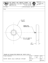
DRAIN—Drain valves externally controlled. Overflow assemblies with skimmer caps are removable without use of tools for drain line inspection. Heaters
protected by low water level control.
UNLOAD TABLE—A stainless steel tray unload table receives clean trays. Table constructed with guide rails which ease the trays onto table.
Motor size Electric usage Steam consump
tion
at 20 psi min.
Final rinse peak flow
at 20 psi min.
15 kw wash tank
Capacity per hour
Tank Capacity
2 hp (wash)
17 kw booster 40°rise
630 trays 24.1 gals. 1/8 hp(conveyor) 30 kw boosters 70°rise
54 lbs./hr. tank 2.8 gals./min.
Current Draw
Amps
208/3/60
Steam
10
Electric
W/O Booster
52
230/1/60 N/A N/A
230/3/60 10 48
380/3/60 8 31
Final rinse
consumption at
20 psi min.
168 gals./hr.
Exhaust hood
requirement
100 CFM Load
300 CFM Unload
Peak rate
drain flow
9 gals./min.
Shipping
weight
660 Ibs.
460/3/60 6 25
2M 5-94—Printed in U.S.A. Insinger's Full Line Specification Data Available in First Place.™


Note: For all rough in connections see Installation and Layout Detail Drawing.
SPECIFICATIONS
CONSTRUCTION—Hood and tank constructed of 16 gauge 18-8 type 304 S/S. Hood unit of all welded seamless construction. S/S frame
and legs. All internal castings are non-corrosive lead free nickel alloy, bronze or S/S investment.
DOORS—Two extra large die formed 18-8 type 304 S/S front inspection doors riding in all S/S channels. A triple ply leading edge on the
door channels made of S/S with no plastic or nylon sleeves or liners used. Two intermediate S/S door-safety stops on the door.
CONVEYOR—One S/S roller conveyor chain with tray cradles. Width between guide rails is adjustable from 1.5" to 4.0". Conveyor
accommodates trays up to 16" high. Conveyor drive system includes direct drive gear motor with slip clutch system, continuously running.
Trays conveyed automatically through washing and rinsing systems powered by independent conveyor motor.
PUMP—Centrifugal type "packless" pump with a brass petcock drain. Construction includes ceramic seal and a balanced cast impeller on
a precision ground stainless steel shaft. All working parts mounted as an assembly and removable as a unit without disturbing pump
housing. One 2 HP motor, 1725 RPM - wash, standard frame, horizontal C-faced, drip proof, squirrel-cage, induction run type, 60 cycle,
internally cooled with ball-bearing construction.
CONTROLS— Top-mounted control cabinet, NEMA 12 rated with heat insulation provided between hood and control cabinet, housing
motor controls and overload protection, transformer, contactors and all dishwasher integral controls. All controls safe low voltage 24 VAC.
ENERGY SAVER—Electric photo eye automatically operates the final rinse solenoid only when a tray passes, saving water and energy.
The eye also activates an adjustable timer control, if no tray passes during the set time, the machine shuts down.
SPRAY SYSTEM—Pre-wash, wash and final rinse spray systems arms made of 18-8 type 304 stainless steel schedule 40 pipe. Spray
assemblies removable without the use of tools.
Pre-wash-Four wash arms threaded into s/s manifold. The wash arms are schedule 40 s/s pipes. (2 on each side on conveyor) Each pipe
designed with 8 high pressure action cleansing slots. The slots precision milled for water control producing a fan spray.
Final Rinse-eight nozzle assemblies on either side of conveyor threaded into s/s schedule 40 pipes. Nozzle assemblies produce a cone
spray reducing water consumption, maximizing heat retention.
DRAIN—Drain valves externally controlled. Overflow assemblies with skimmer caps are removable without use of tools for drain line
inspection. Heaters protected by low water level control.
UNLOAD TABLE—A stainless steel tray unload table receives clean trays. Table constructed with guide rails which ease the trays onto
table.
Insinger's Full Line Specification Data Available in First Place.™
ZM 5-14—Printed In U.S.A
Electric usage
15
kw wash tank
Tank capacity
10.3 gals. (pre-wash)
Motor size
1/2 hp (pre-wash)
2 hp (wash)
17 kw booster 40°rise
Capacity
per hour
630-840 trays
22.5 gals. (wash)
1/8 hp (conveyor)
30 kw boosters 70°rise
Steam consump
-
tion at 20 psi min.
54 lbs./hr. tank
Final rinse peak flow
at 20 psi min.
2.8 gals./min.
Current draw Steam Electric
amps
230/1/60................................n/a........................n/a
230/3/60 ................................12........................ 50
Exhaust hood
requirement
100 CFM Load
380/3/60................................ 10........................ 33
Final rinse
consumption at
20 psi min.
168gals./hr.
300 CFM Unload
Peak rate
drain flow
14 gals./min.
Shipping
weight
740 Ibs.
460/3/60................................. 8..........................27


Insinger
Machine Company
TRAYWASHER
INSTALLATION INSTRUCTIONS
Section A
A.1 PLACEMENT
A.1.1 Carefully uncrate machine. Take caution to not damage components which may be mounted on the
top or sides of the machine.
A.1.2 Set unit in place and adjust the feet to level the machine.
A.1.3 Fasten the table (optional) to the load side of the machine.
Most installations require fastening the turn-down lip of the dish tables to the side of the machine with flathead
counter-sunk screws.
A.2 ELECTRICAL CONNECTIONS
A.2.1 Connect electrical lines sized for the correct voltage, current and phase of the machine. These
should agree with machine requirements indicated on the nameplate and labels in control panel.
A.2.2 On machines not provided with a single-point connection there is an electrical connection required
for the, 1. Pumps and control circuit, and 2. Wash tank heater(s).
A.2.3 If an electrical booster is provided connect the power directly to the booster.
NOTE: In each case connections must be made to a circuit breaker or fused disconnect as provided by
the end-user and required by local codes. A wiring diagram is supplied inside the control panel. Please
return diagram when finished.
IMPORTANT: As with any 3 phase system, an electrician should check all motors for proper phasing,
i.e., Pump motors must be running in direction indicated by arrow on housing.
A.3 MECHANICAL CONNECTIONS
A.3.1 Connect 140DEGF water lines for tank fills and booster as tagged and noted on the installation
drawings.
A.3.2 If machine is provided with steam heat connect the steam lines and steam condensate lines as
tagged and noted on installation drawings.
A.3.3 Connect the drain lines.
A.3.4 If a booster is provided a 140DEGF water connection is necessary. If a steam booster is provided
there is also a condensate line needed.
rlsd: 4/91
cm \wp51\mnltrac.doc

Insinger
Machine Company
TRAYWASHER
INSTALLATION INSTRUCTIONS
Section A
NOTE: Drain lines must be as specified on installation drawings. Drain line should be properly vented and
should have fall of not less than 1/4" to the foot of proper flow. Some area plumbing codes require drains to
flow into an open gap with an opening twice the diameter of the pipe. Check with your local plumbing codes for
the type of drain connection required.
NOTE: All lines should be flushed prior to use to remove debris.
IMPORTANT: Do not reduce the size or lines as specified in installation drawings. All lines are sized to
facilitate necessary flows, pressures, etc.
A. 4 HVAC
A.4.1 Ventilation system should be sized to provide adequate ventilation per machine specs. Refer to
spec sheet.
A.4.2 Stainless steel, watertight ducting should be connected to the vent cowls on each end of the
machine.
A.5 Chemicals
A.5.1 Upon completed installation of the dishwasher contact a local detergent/chemical supplier for the
correct chemicals for your area.
A.5.2 Electrical connection points for the detergent dispenser and rinse injector are located inside the
control panel. Refer to the wiring diagram for this machine for the proper connection points.
Dispensers may be connected on either the primary voltage side of the machine or the 24 VAC
control voltage side.
IMPORTANT: When connecting on the 2 4 VAC control voltage side of the transformer, total KVA must
not exceed .5KVA.
A.5.3 The detergent density probe should be located in a convenient place in the wash tank.
A.6 Tabling
A.6.1 Unload table should be pitched towards the machine to return excess water into the machine.
rlsd: 4/91
cm \wp51\mnl\mnltrac.doc

Insinger
Machine Company
TRAYWASHER OPERATION
Section B
Insinger traywashers are user-friendly, making them the easiest dishwashers on the market to operate and
maintain.
By following the operation procedure and general cleaning procedures your Insinger traywasher will give you
years of trouble free service.
B.1 Operation Instructions
B.1.1 Ensure drain overflow tube is in place close all tank drain valves. One drain is provided for each
tank of the traywasher.
B.1.2 Check for proper installation and cleanliness of all internal, removable components such as suction
strainers, scrap screens, and spray manifolds.
B.1.3 Ensure all water, and steam lines are open. Ensure electrical circuits are on.
B.1.4 Close machine doors.
Note: An interlock is provided to shut the machine down if the doors are open, therefore the machine
will not run if doors are opened. Machines provided with the Prison Package do not have this feature.
B.1.5 Move the power toggle switch to the "ON" position.
B.1.6 For machines provided with the auto tank fill option, the machine will begin to fill. If the machine
does not have auto tank fill, open the tank fill ball valve for each tank.
B.1.7 When the tanks are full the tank heat will operate automatically.
IMPORTANT: To ensure proper operation of the auto tank fill feature and the tank beaters the two (2)
level floats located in each tank MUST be cleaned daily.
B.1.8 Depress the Green button to start the conveyor system.
B.1.9 The system is now ready for operation. All ware should be properly scrapped.
B.1.10 Place the tray on the conveyor belt. The tray will pass the through the various machine cycles. The
final rinse is automatically started when the tray passes the photo-eye located at the entrance chute
for the machine.

Insinger
Machine Company
TRAYWASHER
OPERATION
Section B
IMPORTANT: The photo-eye located at the entrance chute of the machine should be cleaned daily of lime
build-up for proper operation of the energy saver feature and the final rinse.
B.1.11 Upon completion of ware cleaning depress the Red button to stop the conveyor system.
B.1.12 Move the Power toggle switch to the "OFF" position.
IMPORTANT: Move the Power toggle switch to the "OFF" position before draining the machine.
B.1.13 Refer to the cleaning procedures for proper clean-up of the dishmachine.
B.1.14 Report any unusual occurrences to qualified service personnel.
The following cleaning procedures should be done daily, at the end of the shift.
B.2 Cleaning Procedures, Daily
B.2.1 Remove all internal removable parts including spray manifolds, scrap screens, drain overflow tubes,
suction strainers and curtains.
B.2.2 Remove the end caps from the spray manifolds and clean with the brush provided. Flush the
manifolds.
B.2.3 Flush scrap screens.
B.2.4 Clean drain overflow tube.
Note: V-cup seal on the drain overflow tube may become gummed not allowing a proper seat of the
overflow tube. This will cause the drain to leak water. Remove any build-up on the V-cup seal. When the
seal becomes worn, replace.
B.2.5 Clean suction strainers of build-up.
Note: Improper cleaning of suction strainers will cause the pumps to cavitate. This will cause poor
washing results.
rlsd: 4/91
cm \wp51\mnl\mnltrac.doc

Insinger
Machine Company
TRAYWASHER
OPERATION
Section B
B.2.6 Clean tank level floats (1 per tank) with Scotch-Brite or equivalent.
Important: Level floats must be cleaned daily. Build-up of grease and scum will cause faulty
operation of tank fill and heating system.
B.2.6 Clean curtains. When curtains are beyond cleaning, or torn, they should be replaced.
B.2.7 Final rinse nozzles should be cleaned of matter clogging the jet spray.
B.2.8 Clean the photo-eye lenses with a damp, soft cloth.
B.2.9 Doors should be left open to allow drying of interior surfaces.
rlsd: 4/91
cm\wp51\mnl\mnltrac.doc

Insinger
Machine Company
TRAYWASHER
MAINTENANCE and REPAIR PROCEDURES
Section A
Following is a basic guide for the repair and replacement of common traywasher parts.
Refer to the Basic Service Guide for troubleshooting tips.
A.1 MAINTENANCE
A.1.1 Daily - Refer to the operation and cleaning instructions provided in this manual for daily cleaning
procedures.
A.1.2 Weekly
A.1.2.1 The entire machine should be wiped down using an industrial grade stainless steel cleaner.
A.1.2.2 Under the supervision of your detergent supplier the machine interior must be properly de-limed.
NOTE: The water quality in some areas requires de-liming to be done more frequently. Contact your
detergent supplier for recommended de-liming frequency.
A.1.3 Quarterly
A.1.3.1 Remove and clean the strainer screens on water and steam lines. If the screens cannot be
cleaned, replace.
A.1.3.2 Inspect condition of solenoid valve seats and diaphragms. Replace where necessary.
A.1.3.3 Inspect drain 0-Rings for leakage. Replace where necessary.
A.1.3.4 Adjust conveyor chain tension using adjustment bolts located at machine entrance chute.
A.2 MAINTENANCE PROCEDURES
A.2.1 Solenoid Valve Disassembly
A.2.1.1 Disconnect power supply to machine. Turn off Water supply.
A.2.1.2 Remove cap on top of coil. Remove coil.
A.2.1.3 Remove 4 hex bolts and lift bonnet from valve body. Note positioning of spring and plunger.
A.2.1.4 Remove main piston.
A.2.1.5 Inspect for dirt, wear or lime build-up. Clean or replace as required.
A.2.1.6 Reassemble in reverse of disassembly.
rlsd: 4/91
cm\wp51\mnl\mnltrac.doc

Insinger
Machine Company
TRAYWASHER
MAINTENANCE and REPAIR PROCEDURES
Section A
A.2.2 Line Strainer Disassembly
A.2.2.1 Shut off water or steam supply.
A.2.2.2 Remove large hex nut on bottom of strainer body.
A.2.2.3 Remove strainer screen. Inspect and clean or replace as necessary.
A.2.2.4 Reassemble in reverse of disassembly. Water flow must be same direction as arrow on line
strainer body. Use new gaskets to ensure a tight seal.
A.2.3 Pump Disassembly
A.2.3.1 Before disassembling pump ensure there are no obstructions in the pump intake. Remove and
clean the suction strainer (inside tank).
A.2.3.2 IT IS NOT NECESSARY TO REMOVE THE PUMP HOUSING FROM THE MACHINE TO
DISASSEMBLE THE PUMP.
A.2.3.3 Remove the pump motor and impeller adaptor by removing the 4 hex bolts attaching them to the
pump housing.
A.2.3.4 Repair or replace the pump parts as required.
A.2.3.5 Reassemble in reverse of disassembly.
A.2.4 Immersion Heater Replacement
A.2.4.1 The immersion heater MUST be completely submerged at all times. If this is not the case contact
a qualified service technician. The heated surface should never be in contact with sludge.
A.2.4.2 Remove the housing covering the wiring terminations. Disconnect the immersion heater wires.
A.2.4.3 Remove the immersion heater by loosening and removing the large hex nut.
A.2.4.4 Install in reverse of removal.
NOTE: USE PLUMBERS’ PUTTY AS GASKETING AROUND THE IMMERSION HEATER TO INSURE NO
LEAKS.
A.2.5 Tank Heat Temperature Adjustment
A.2.5.1 A temperature control board is provided in the control panel for easy adjustment of tank
temperature. Though tank temperature is adjusted during the machine’s factory test, it is
sometimes necessary to re-adjust the temperature at start -up.
A.2.5.2 Locate the temperature control board (P/N DE9-96). Use the control panel layout drawing located
in Section 3, Electrical Schematic and Replacement Parts.
cm\wp51\mnl\mnltrac.doc
rlsd: 4/91

Insinger
Machine Company
TRAYWASHER
MAINTENANCE and REPAIR PROCEDURES
Section A
A.2.5.3 Adjust the tank temperature to the desired temperature by turning the potentiometer located on the
temperature control board. An arrow on the potentiometer indicates increase.
A.2.5.4 If the temperature does not change refer to section A.2.6, Troubleshooting Tank Temperatures.
A.2.6 Troubleshooting Tank Temperatures
A.2.6.1 Electric Heat
A.2.6.1.1 If temperature cannot be adjusted per section A.2.5 check the temperature control board
P/N DE9-96 proper operation. If the temperature control board is faulty, replace.
A.2.6.1.2 Verify tank heat contactor is working correctly. If not, replace.
A.2.6.1.3 Verify all immersion heaters are working properly and not limed. If not, replace.
A.2.6.2 Steam Heat
A.2.6.2.1 See Section A.2.6.1.1.
A.2.6.2.2 Verify steam pressure per machine specifications.
A.2.6.2.3 Verify steam trap is not clogged. If so, replace.
A.2.7 Motor Overloads
A.2.7.1 All motors used on Insinger Machines are provided with motor overloads. Motor overloads are
adjusted when the machines are factory tested. Should it be necessary to adjust the motor
overloads in the field, first verify the motor current draw for the voltage the machine is using.
A.2.7.2 Using the Control Panel Component Layout Dwg. located in Section 3 to identify the overload adjust
by turning the dial to the appropriate AMP draw.
cm \wp51\mnl\mnltrac.doc
rlsd: 4/91

Insinger
Machine Company
TRAYWASHER
MAINTENANCE and REPAIR PROCEDURES
Section A
A.2.8 Level System
A.2.8.1 The level control system consists of one level timer (P/N DE7-31) and one level float (DE5-60)
per tank.
A.2.8.2 When the system is powered-up, the tank(s) will begin to fill (assuming no water is in the tanks).
A.2.8.3 Once the level float is actuated, the timer begins to time-out and continues the filling process until
the tank(s) is full.
IMPORTANT: Dirty level floats will cause the tank heat to energize with no water in the tanks. LEVEL
FLOATS MUST BE CLEANED DAILY.
A.2.9 Final Rinse
A.2.9.1 The final rinse is actuated by a photo-eye located on the entrance chute. As a tray passes the
photo-eye the beam is broken. The Final Rinse timer (P/N DE7-27) will energize the final rinse
solenoid. The final rinse water will then flow.
A.2.9.2 The Energy Saver timer (P/N DE7-28) is also reset keeping the machine running.
A.2.9.3 Both timers are adjustable by turning the potentiometer located on the timer board. The final rinse
timer is adjustable 0-60SEC. The energy saver timer is adjustable 0-300SEC.
cm\wp51\mnl\nmltrac.doc
rlsd: 4/91
/