Page is loading ...

6245 State Rd. Telephone 215-624-4800
Philadelphia, PA 800-344-4802 19135-2996
Fax:215-624-6966
www.insingermachine.com
TECHNICAL MANUAL
FOR
DOOR TYPE
DISHWASHING
MACHINE
MODELS
COMMANDER 18-5
COMMANDER 18-5C
COMMANDER 18-5H CS
5 CS-5C

TECHNICAL MANUAL
including Installation, Operation, and Maintenance Instructions
FOR
DOOR TYPE DISHMACHlNES
MODELS
Commander 18-5
Commander 18-5C
Commander 18-5H
CS-5
CS-5C
rlsd: 1/97
s:\wp51\manual\mnll841

6245 State Road Telephone 215.624.4800
Philadelphia FAX: 215 624 6966
PA 19135-2996
Thank you for Purchasing this quality Insinger product.
On the space provided please record the Model and Serial Number of this unit:
Model: ______________________
Serial Number: _______________
When referring to this equipment please have these numbers available.
Each piece of equipment at Insinger is carefully tested before shipment for proper operation.
If the need for service should arise please contact your local Authorized Insinger Service
Company. A Service Network Listing is provided within this manual. Check this list for your
local authorized servicer.
For proper activation of the Insinger Limited Warranty a SureFire™ Start-up should be completed
on your machine. Refer to the Introduction section in this manual for an explanation of
Insinger's SureFire™ Start-up and Check-out Program.
Please read the Insinger Limited Warranty and all installation and operation instructions
carefully before attempting to install or operate your new Insinger product.
To register your machine for warranty by phone, fax, or the internet or for answers to questions
concerning installation, operation, or service contact our Technical Services Department:
Toll-Free 800.344.4802
Fax 215.624.6966
Email service@insingermachine. com
World-Wide Web http://WWW.insingermachine.corn
Thank you.
Insinger Machine Company
S:\WP51\MANUAL\INTRO

DOOR TYPE DISHMACHINES MODEL:
Commander 18-5 & CS Series
Table of Contents
Part 1 - Technical Information
• Section A, Introduction
• Catalogue Cut-sheet and Installation Drawing
• Warranty
• Authorized Service Agency Network Listing
Part 2 - Installation and Operation Instructions
• Section A, Installation Instructions
• Section B, Operation and Cleaning Instructions
• Part 3 - Maintenance and Repair Procedures
• Section A, Maintenance and Repair Procedures
• Basic Service Guide
Part 3 - Electrical Schematics and Replacement Parts
• Machine Wiring Diagrams
• Control Panel Layout and Component Drawing
Part 4 - Replacement Parts
• Overall Assembly Drawing for:
Commander 18-5, 18-5H, CS-5
Commander 18-5C, CS-5C
• Drain Assembly
• Motor Assembly, 1HP
• Pump, Motor & Suction Assembly
• Level Float Installation
• Electric Heater, Diode and Level float
• Steam Injectors, Steam Coils and Steam Booster Assembly's
• Final Rinse Assembly
• Final Rinse Assembly (self-contained booster)
• Electric Booster Assembly
• Self Contained Booster Assembly
• Gas-heated Machines •
Parts Listing
Troubleshooting
Sequence of Operations
rlsd: 1/97, 10/98
s:\wp51\manual\mnl185

COMMANDER 18-5 Series & CS Series
TECH MANUAL INTRODUCTION
Part 1, Section A
1.A. INTRODUCTION
I.A.I Purpose
The purpose of this Tech Manual is to provide installation, operation, cleaning and maintenance directions. A
section is provided for replacement parts.
1.A.2 Scope
This manual contains all pertinent information to assist in the proper installation, operation, cleaning,
maintenance, and parts ordering for the Commander 18-5 series and CS-5 series dishwashers. The installation
instructions are intended for qualified equipment installers. The operation and cleaning instructions are
intended for the daily users of the equipment. The maintenance and parts sections are intended for qualified
service and/or maintenance technicians. Replacement parts may be ordered directly from our factory or from
your local Insinger Authorized Service Agency. For the name of your local Insinger Authorized Service
Agency please reference the Service Network Listing in Section 1 of this manual. You can also speak to the
Insinger Technical Services Department, 800/344-4802, or e-mail us at [email protected].
When calling for warranty information or replacement parts please provide the model and serial number of
your Insinger equipment. These important numbers should be noted in this manual on the spaces provided on
the opening page.
1.A.3 Surefire™ Start-Up Program
Insinger is proud to offer our exclusive Surefire™ Start-up & Check-out Program to our commercial
customers. This service is included in the purchase price of your new Insinger dishwasher. We will provide an
authorized factory service technician for the initial start-up of your new Insinger dishwasher to ensure it is
running correctly. Please call the factory or your local Insinger Sales or Service Representative to schedule
this service.
1.A.4 Definitions
Throughout this guide you will find the following terms: WARNING, CAUTION, & NOTE. When used,
these terms will be outlined in a box to draw attention:
WARNING indicates potential physical danger.
CAUTION indicates potential equipment damage.
NOTE indicates helpful operating hints or tips.
rlsd: 1/97, 10/98
s:\wp51\manual\mnl 185

Item #
COMMANDER 18-5
AUTOMATIC SINGLE TANK
DOOR TYPE DISHWASHER
DESIGN
Automatic door type, single tank dishwasher with timed wash and
rinse cycle. Fully automatic operation with power on/off button.
Capacity is 60 - 20" X 20" racks per hour, or 1500 dishes per hour.
Cycle starts when doors are closed. Designed for straight through
operation. Corner model available for right angle operation.
• Elevated top-mounted control panel
(NEMA12)
• Easily-cleaned crowned hood top
• "Easy Clean" front-mounted wash tank
• Capillary thermometer for wash
• In-line thermometer for final rinse
• Manifold cleanout brush
• Inspection door
• S/S frame, legs and feet
• Automatic tank fill
• Low water protection
• Override switch for de-liming or extended
wash cycle
• Vent fan connection provision
OPTIONAL ACCESSORY EQUIPMENT
·
Pressure reduction valve
·
Remote electric booster
and line strainer
·
Security package
·
Stainless steel steam coil
·
Totally enclosed motor
tank heat
•
Door activated drain closer
·
Gas tank heat
·
Plastic 20" x 20" racks
·
Steam booster (plate or silver)
·
Built-in electric booster
·
S/S front panel
6245 State Road
Philadelphia,PA19135-2996
215/624-4800
215/624-6966 FAX
800/344-4802
www.insingermachine.com
STANDARD EQUIPMENT
• Space saving compact design
• Door safety switch
• Detergent connection provision
• Fully automatic operation
• Single scrap screen design
• Non-proprietary commercially
available pump motor
• Easily removable pump suction
strainer
• Tank heat: 3KW electric immersion
heater or steam injector
• SureFire™ Start-Up and Check-Out
Service
• Vacuum breaker

COMMANDER 18-5
Note: For all rough in connections see Installation and Layout Detail Drawing.
SPECIFICATIONS
CONSTRUCTION-Hood and tank constructed of 16 gauge 18-8 type 304 S/S. Hood unit of all welded seamless construction. S/S frame, legs and
feet. All internal castings are non-corrosive lead free nickel alloy or bronze.
DOORS-a front inspection/cleanout door and two simultaneously opening operating doors. Operating doors have fingertip control, balanced by
externally mounted springs. (Corner model available with 2 doors at right angles.) Extra large die formed 18-8 type 304 S/S doors ride in all S/S
channels. A triple ply leading edge on the door channels made of S/S with no plastic or nylon sleeves or liners used.
PUMP-Centrifugal type "packless" pump with a brass petcock drain. Construction includes ceramic seal and a balanced cast impeller on a precision
ground stainless steel shaft. All working parts mounted as an assembly and removable as a unit without disturbing pump housing. One 1 HP motor,
standard frame, horizontal C-faced, drip proof, squirrel-cage, induction run type, 3400 RPM, internally cooled with ball-bearing construction.
CONTROLS-Top-mounted control cabinet, NEMA 12 rated, housing motor controls and overload protection, transformer, contactors and all
dishwasher integral controls. All controls safe low voltage 24 VAC.
SPRAY SYSTEM- Wash and rinse spray systems made of 18-8 type 304 stainless steel pipe threaded into cast hub assemblies. Upper
and lower wash and rinse spray assemblies are removable without the use of tools.
WASH- 2 power spinning wash arms above and 2 power spinning wash arms below. On top, each wash arm is designed with 8 nozzles (16 total).
On the bottom, each wash arm is designed with 4 slots (8 total). The slots are precision milled for water control and produce a fan spray.
FINAL RINSE-2 power spinning rinse arms above and 2 power spinning rinse arms below. On top, each rinse arm is designed with 2 nozzles (4
total). On the bottom, each rinse arm is designed with 4 nozzles (8 total). The nozzles produce a fan spray reducing water consumption, maximizing
heat retention.
DRAIN-Drain valve externally controlled. Overflow assembly with skimmer cap is removable without use of tools for drain line inspection. Heater
protected by low water level control.
Capacity Tank capacity Motor size Electric usage Steam Final rinse
per hour
3 kw wash tank
consumption at
20
psi min.
peak flow
at 20 psi min.
60
racks
13.5
kw b.i.booster
40°
or
70°
rise
18lbs./hr
tank
1500
dishes
6
kw rem. booster
40°
rise
24
lbs./hr booster
40°
rise
75-150 meals 6.4 gals. 1 hp (wash) 12 kw rem. booster 70° rise 42 lbs./hr booster 70° rise
3.25 gals./min.
Exhaust hood
requirement
Current draw
amps
115/1/60
Steam/gas
.
17
Electric w/o
booster
42
Electric w/
built-in booster
n/a
208/3/60
5
1
3
51
240/1/60
9
23
84
240/3/60
4
12
44
380/3/50
3
8
n/a
Final rinse
consumption at
20 psi min.
60 gals./hr. 1.0
gals./rack
100CFM
Peak rate
drain flow
9 gals./min.
Shipping
weight
550 Ibs.
480/3/60 2 6 22
3M 9.97 PRINTED IN USA
INSINGER'S FULL LINE SPECIFICATION AVAILABLE IN FIRST PLACE™ and AutoQuotes™

File: STD/18
-
5
*
ADD 3 KW FOR ELECTRIC HEA T, PLUS
13.5 KW FOR BUILT-IN ELECT. BOOSTER.
** 10 KW FURNISHED WHEN SPECIFIED.
? FOR HOT WATER TO BOOSTER 140' F
STANDARD / 110' F SPECIAL
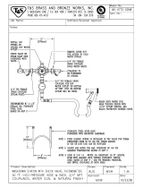
NOTES:
1. WASH TANK IS FILLED THRU THE FINAL RINSE
LINE.
2. FOR GAS HEATED MACHINE SEE DWG 18-5G.
INSTALLATION
AND LAYOUT
DETAIL
INSTALLATION CONNECTIONS
LTR
DESCRIPTION SIZE
A HOT WATER TO FINAL RINSE - 180' F 1/2 FIPS
B HOT WATER TO REMOTE ELEC. BOOSTER? 1/2 FIPS
C HOT WATER TO STEAM BOOSTER ? 1/2 F!PS
D STEAM TO TANK 1/2 FIPS
E STEAM TO STEAM BOOSTER 1/2 FIPS
F DRAIN CONNECTION
1 1/2
FIPS
G CONDENSATE RETURN - STEAM BOOSTER 1/2 FIPS
H CONDENSATE RETURN - COIL ONLY 2/8 FIPS
J ELECTRICAL CONNECTION - MOTORS 1 HP *
K ELECTRICAL CONNECTION-REMOTE BOOSTER
6 KW **
L HOT WATER TO B.I. ELEC. BOOSTER
?
1/2 FIPS
COMMANDER
18
-
5
AUTOMATIC DISHWASHING MACHIHE
6245
State Rd. Tel.
215
-
624
-
4800
Philadelphia FAX: 215-624-6966
PA 19135-2996
DWG. NO.
18-5
SCALE: 3/4" =
1’
-
0"
DRAWN: EMM 7.21.98
APPROVED: EBA 7.21.98

INS TALLA TION CONNEC TIONS
LTR
DESCRIPTION SIZE
A HOT WATER TO FINAL RINSE - 180° F 1/2 FIPS
B HOT WATER TO REMOTE ELEC. BOOSTER ? 1/2 FIPS
C HOT WATER TO STEAM BOOSTER ? 1/2 FIPS
D STEAM TO TANK 1/2 FIPS
E STEAM TO BOOSTER 1/2 FIPS
F DRAIN CONNECTION 1 1/2 FIPS
G CONDENSATE RETURN - STEAM BOOSTER 1/2 FIPS
H CONDENSATE RETURN - COIL ONL Y 3/8 F!PS
J ELECTRICAL CONNECTION - MOTORS 1 HP *
K ELECTRICAL CONNECTION-REMOTE BOOSTER
6 KW **
L HOT WATER TO B.I. ELECT. BOOSTER? 1/2 FIPS
*
AD
D 3KW FOR ELECTRIC HEAT, PLUS
13.5 KW FOR BUILT-IN ELECT. BOOSTER.
** 10 KW FURNISHED WHEN SPECIFIED.
? FOR HOT WATER TO BOOSTER 140' F
STANDARD / 110' SPECIAL
NOTES:
1. WASH TANK IS FILLED THRU THE FINAL RINSE
LINE.
2. FOR GAS HEATED MACHINE SEE DWG. 18-5CG
COMMANDER 18
-
5C
AUTOMATIC DISHWASHING MACHINE
6245 State Rd. Tel. 215
-
624
-
4800
Philadelphia FAX; 215-624-6966
PA 19135-2996
DWG. NO.
18-5C
SCALE: 3/4" =1'
-
0"
DRAWN: EMM 7.21.98
APPROVED: EBA 7.21.98

COMMANDER
18
-
5
(GAS)
AUTOMATIC DISHWASHING MACHINE
6245
State Rd. Tel.
215
-
624
-
4800
Philadelphia TWX: 710-670-1233
PA 19135-2996 FAX: 215-624-6966
DWG. NO.
18-5G
scale 3/4"
=
1'
-
0"
DRAWN: EMM 7.22.98
APPROVED: EBA 7.22.98
NOTE:
1. WASH TANK IS FILLED THRU THE FINAL
RINSE TANK.
* 2. ALLOW 2 FEET MINIMUM FROM A
VERTICAL COMBUSTIBLE WALL.
INS TALLATION CONN EC TIONS
LTR
DESCRIPTION SIZE
A HOT WATER TO FINAL RINSE - 180° F 1/2 FIPS
B DRAIN CONNECTION 1 1/2 FIPS
C GAS CONNECTION 3/4 FIPS
D ELECTRICAL CONNECTION 1 HP
E FLUE 1 3/4x5

INSTALLATION CONNECTIONS
LTR
DESCRIPTION SIZE
A HOT WATER TO FINAL RINSE - 180° F ½ FIPS
DRAIN CONNECTION 1 1/2 FIPS
B
C
GAS CONNECTION 3/4 FIPS
D ELECTRICAL CONNECTION 1 HP
E FLUE 1 3/4x5
NOTES:
1. WASH TANK IS FILLED THRU THE FINAL
RINSE LINE.
*2. ALLOW 2 FEET MINIMUM FROM A
VERTICAL COMBUSTIBLE WALL.
COMMANDER 18-5C (GAS)
AUTOMATIC DISHWASHING MACHINE
6245
State Rd. Tel. 215
-
624
-
4800
PhiladelphIa FAX: 215-624-6966
PA 19135-2996
DWG. NO.
18-5CG
SCALE:
¾ “
-
1'
-
0"
DRAWN: EMM 7.22.98
APPROVED: EBA 7.22.98

Item #________
COMMANDER 18-5H
AUTOMATIC SINGLE TANK DOOR TYPE
WAREWASHER & TRAY/UTENSIL
WASHER
DESIGN
Automatic door type, single tank dishwasher with timed wash and rinse cycle.
Fully automatic operation with power on/off button. Capacity is 60 - 20" X 20"
racks per hour, or 1500 dishes per hour. The 18-5H can also handle mixer
agitators, 18" X 26" sheet pans, utensils and mixing bowls up to 60 quarts!
Cycle starts when doors are closed. Designed for straight through operation.
Corner model available for right angle operation.
STANDARD EQUIPMENT
• Space saving compact design • Top-mounted control panel
• Door safety switch (NEMA 12)
• Detergent connection provision • "Easy Clean" front-mounted
• Fully automatic operation wash tank
• Single scrap screen design • Capillary thermometer for wash
• Non-proprietary commercially • In-line thermometer for final rinse
available pump motor • Manifold cleanout brush
• Easily removable pump • Inspection door
suction strainer •S/S frame, legs and feet
• Tank heat: 5KW electric • Automatic tank fill
immersion heater or • Low water protection
steam injector • Override switch for de-liming
• SureFire™ Start-Up and or extended wash cycle
Check-Out Service • Vent fan connection provision
• Vacuum breaker
OPTIONAL ACCESSORY EQUIPMENT
• Pressure reduction valve • Remote electric booster
and line strainer • Security package
• Stainless steel steam coil • Totally enclosed motor
tank heat • Door activated drain closer
• Gas tank heat • Plastic 20" x 20" racks
• Steam booster (plate or silver)
• Built-in electric booster • S/S front panel
6245 State Road
Philadelphia, PA 19135-2996
215/624-4800
215/624-6966 FAX
800/344-4802
www.insingermachine.com
CSI-11400

COMMANDER 18-5H
Note: For all rough in connections see Installation and Layout Detail Drawing.
SPECIFICATIONS
CONSTRUCTION-Hood and tank constructed of 16-gauge 18-8 type 304 S/S. Hood unit of all welded seamless construction. S/S frame, legs and feet.
All internal castings are non-corrosive lead free nickel alloy or bronze.
DOORS-A front inspection/cleanout door and two simultaneously opening operating doors. Operating doors have fingertip control, balanced by
externally mounted springs. (Corner model available with 2 doors at right angles.) Extra large die formed 18-8 type 304 S/S doors ride in all S/S
channels. A triple ply leading edge on the door channels made of S/S with no plastic or nylon sleeves or liners used.
PUMP-Centrifugal type "packless" pump with a brass petcock drain. Construction includes ceramic seal and a balanced cast impeller on a precision
ground stainless steel shaft. All working parts mounted as an assembly and removable as a unit without disturbing pump housing. One 2 HP motor,
standard frame, horizontal C-faced, drip proof, squirrel-cage, induction run type, 3400 RPM, internally cooled with ball-bearing construction.
CONTROLS-Top-mounted control cabinet, NEMA 12 rated, housing motor controls and overload protection, transformer, contactors and all
dishwasher integral controls. All controls safe low voltage 24 VAC.
SPRAY SYSTEM- Wash and rinse spray systems made of 18-8 type 304 stainless steel pipe threaded into cast hub assemblies. Upper and
lower wash and rinse spray assemblies are removable without the use of tools.
WASH- 2 power spinning wash arms above and 2 power spinning wash arms below. On top, each wash arm is designed with 8 nozzles (16 total). On
the bottom, each wash arm is designed with 4 slots (8 total). The slots are precision milled for water control and produce a fan spray.
FINAL RINSE-2 power spinning rinse arms above and 2 power spinning rinse arms below. On top, each rinse arm is designed with 2 nozzles (4 total).
On the bottom, each rinse arm is designed with 4 nozzles (8 total). The nozzles produce a fan spray reducing water consumption, maximizing heat
retention.
DRAIN-Drain valve externally controlled. Overflow assembly with skimmer cap is removable without use of tools for drain line inspection. Heater
protected by low water level control.
Capacity per hour Tank capacity Motor size
Electric usage
5 kw wash tank
Steam consumption
at 20 psi min.
Final rinse peak
flow at 20 psi min.
60 racks
13.5 kw b.i.booster 40°
or 70° rise
70°rise
18lbs./hr tank
1500 dishes
6 kw rem. booster 40° rise
24 lbs./hr booster 40°
rise
75-150 meals 6.4 gals. 2 hp (wash) 12 kw rem. booster 70° rise
42 lbs./hr booster 70°
rise
3.25 gals./min.
Final rinse
consumption
Current draw
amps
208/3/60
Steam/gas
8
Electric Electric w/
w/o booster built-in booster
21.9 59. 9
240/1/60 13 33.8 94.8
240/3/60 7 2 19.2 51.2
380/3/50 4.4 12 n/a
480/3/60 3.6 9.6 25.6
60 gals./hr.
1.0gal./rack
Exhaust hood
requirement
100CFM
Peak rate
drain flow
9 gals./min.
Shipping
weight
600 Ibs.
3M 9.97 PRINTED IN USA
INSINGER’S FULL LINE SPECIFICATION AVAILABLE N FIRST PLACE™ and AutoQuotes™
CSI- 11400

INSTALLATION CONNECTIONS
LTR
DESCRIPTION SIZE
A HOT WATER TO FINAL RINSE - 180° F 1/2 FIPS
B HOT WATER TO REMOTE ELEC. BOOSTER ?
1/2 FIPS
C HOT WA TER TO STEAM BOOSTER
?
1/2 FIPS
D STEAM TO TANK 1/2 FIPS
E STEAM TO STEAM BOOSTER 1/2 FIPS
F DRAIN CONNECTION 1 1/2 FIPS
G CONDENSATE RETURN - STEAM BOOSTER 1/2 FIPS
H CONDENSATE RETURN - COIL ONL Y 3/8 FIPS
J ELECTRICAL CONNECTION - MOTORS 2 HP *
K ELECTRICAL CONNECTION-REMOTE BOOSTER
6 KW **
L HOT WATER TO B.I. ELEC. BOOSTER
?
1/2 FIPS
* ADD
5
K
W FOR ELECTRIC HEAT, PLUS
13.5 KW FOR BUILT-IN ELECT. BOOSTER.
** 10 KW FURNISHED WHEN SPECIFIED.
? FOR HOT WATER TO BOOSTER 140° F
STANDARD / 110° F SPECIAL.
NOTE:
1. WASH TANK IS FILLED THRU THE FINAL
RINSE LINE.FILE: STD\18-5H
COMMANDER 18-5H
AUTOMATIC DISHWASHING MACHINE
6245
State Rd. Tel.
215
-
624
-
4800
Philadelphia FAX: 215-624-6966
PA 19135-2996
DWG. NO.
18-5H
SCALE:
3/4
"
=
1'
-
0"
DRAWN: Y.G. 12.17.9
APPROVED:

21
,
INSTALLATION CONNECTIONS
LTR
DESCRIPTION SIZE
A HOT WATER TO FINAL RINSE -180° F 1/2 FIPS
B HOT WATER TO REMOTE ELEC. BOOSTER? 1/2 FIPS
C HOT WATER TO STEAM BOOSTER
?
1/2 FIPS
D STEAM TO TANK 1/2 FIPS
E STEAM TO STEAM BOOSTER 1/2 FIPS
F DRAIN CONNECTION 1 1/2 FIPS
G CONDENSATE RETURN - STEAM BOOSTER 1/2 FIPS
H CONDENSATE RETURN - COIL ONL Y 3/8 FIPS
J ELECTRICAL CONNECTION - MOTORS 2 HP *
K ELECTRICAL CONNECTION-REMOTE BOOSTER
6 KW **
L HOT WATER TO B.I. EL EC. BOOSTER
?
1/2 FIPS
*ADD
5
KW FOR ELECTRIC HEAT, PLUS
13.5 KW FOR BUILT-IN ELECT. BOOSTER.
** 10 KW FURNISHED WHEN SPECIFIED.
? FOR HOT WATER TO BOOSTER 140° F
STANDARD / 110° F SPECIAL.
NOTE:
1. WASH TANK IS FILLED THRU THE FINAL RINSE
LINE.
FILE: STD\18-5CH
COMMANDER 18-5CH
AUTOMATIC DISHWASHING MACHINE
6245
State Rd. Tel.
215
-
624
-
4800
Philadelphia FAX: 215-624-6966 PA
19135-2996
DWG. NO.
18-5CH
SCALE: 3/4" = 1'-0""
DRAWN: PG 2.13.98
APPROVED:

CS
-
4
AUTOMATIC SINGLE TANK
CHEMICAL SANITIZING DOOR
TYPE DISHWASHER
DESIGN
Automatic door type, single tank dishwasher with a timed wash and
rinse cycle. Fully automatic operation with power on/off button.
Capacity is 80 racks per hour for light soil (60 racks per hour for normal
soil) - 20" x 20" racks. Cycle starts when doors are closed. Designed
for straight through operation. Corner model available for right angle
operation.
STANDARD EQUIPMENT
OPTIONAL ACCESSORY EQUIPMENT
·
Pressure reduction valve and
line strainer
• Stainless steel steam coil
tank heat
6245 State Road
Philadelphia, PA 19135-2996
215/624-4800
215/624-6966 FAX
800/344-4802
http://www.insingermachine.com
•
Tank heat:
3
KW electric
immersion heater or steam
injector
• NSF approved sanitizer injector
pump
• Capillary thermometer for wash
• In-line thermometer for final rinse
• Vacuum breaker
• Manifold cleanout brush
• Inspection door
• S/S frame, legs and feet
• Automatic tank fill
• Low water protection
•
Deterg
ent connection provision
• Space saving compact design
• Fully automatic operation
• Top mounted control panel
(NEMA12)
• Simplified scrap screen design
• Door safety switch
• Interchangeable upper & lower
wash arms
• Standard frame drip proof motor
• Override switch for de-liming
•
Gas tank heat
·
Security package
• Totally enclosed motors
·
Door activated drain closer

Note: For all rough in connections see Installation and Layout Detail Drawing.
SPECIFICATIONS
CONSTRUCTION-Hood and tank constructed of 16 gauge 18-8 type 304 S/S. Hood unit of all welded seamless construction. S/S
frame, legs and feet. All internal castings are non-corrosive nickel alloy, bronze or S/S investment.
DOORS-a front inspection/cleanout door and two simultaneously opening operating doors. Operating doors have fingertip control,
balanced by externally mounted springs. (Corner model available with 2 doors at right angles.) Extra large die formed 18-8 type 304
S/S doors ride in all S/S channels. A triple ply leading edge on the door channels made of S/S with no plastic or nylon sleeves or liners
used.
PUMP-Centrifugal type "packless" pump with a brass petaock drain. Construction includes ceramic and a balanced cast impeller on a
precision ground stainless steel shaft. All working parts mounted as an assembly and removable as a unit without disturbing pump
housing. One 1 HP motor, standard frame, horizontal C-faced, drip proof, squirrel-cage, induction run type, internally cooled with ball-
bearing construction.
CONTROLS-Top-mounted control cabinet, NEMA 12 rated with heat insulation provided between hood and control cabinet, housing
motor controls and overload protection, transformer, contactors and all dishwasher integral controls. All controls safe low voltage 24
VAC.
SPRAY SYSTEM- Wash and rinse spray systems made of 18-8 type 304 S/S pipe threaded into cast hub assemblies. Upper and lower
wash spray assemblies are interchangeable and are removable without the use of tools.
WASH-2 power spinning wash arms above and 2 power spinning wash arms below each designed with 8 high pressure action
cleansing slots. The slots are precision milled for water control producing a fan spray.
FINAL RINSE-2 power spinning rinse arms above and 2 power spinning rinse arms below each designed with 2 nozzle assemblies.
Nozzle assemblies produce a cone spray reducing water consumption, maximizing heat retention. The final rinse piping is chlorinate
poly vinyl chloride.
DRAIN-
Drain valves
externally
controlled.
Tank capacity Motor size Electric usage Steam consumption
at 20 psi min.
Final rinse peak
flow at 20 psi
min.
1500 dishes
75-150 meals 6.4 gals. 1 hp 3 kw wash tank 11 Ibs/hr tank 3.1 gals./min.
Final rinse
consumption
Exhaust hood
requirements
Peak rate drain
flow
Shipping weight
Current draw
amps
115/1/60
Steam
17
Electric w/o
booster
42
208/3/60
5 13
230/1/60
9 23
41 gals./hr.
230/3/60
4 12
380/3/60
3 8
0.51 gals./rack 100CFM 9 gals./min. 550 Ibs.
460/3/60
2 6
3M 3.98 PRINTED IN USA INSINGER'S FULL LINE SPECIFICATION AVAILABLE IN FIRST PLACE™
CS
-
4

FILE: STD\CS-5
CS
-
5
AUTOMATIC CHEMICAL SANITIZING DISHWASHING
MACHINE
6245
State Rd. Tel.
215
-
624
-
4800
Philadelphia
PA 19135-2996 FAX: 215-624-6966
DWG. NO.
CS-5
SCALE: ¾”
=
1'
-
0"
DRAWN: EMM 10.5.98
APPROVED: EBA 10.5.93
NOTES:
1. WASH TANK IS FILLED THRU THE FINAL
RINSE LINE.
2. CHEMICAL SANITIZER INJECTOR PUMP
FURNISHED.
INS TALLATION CONN EC TIONS
LTR
DESCRIPTION SIZE
A HOT WATER 70 FINAL RINSE - 140' F 1/2 FIPS
B STEAM TO TANK COIL 1/2 FIPS
C DRAIN CONNECTION 1 1/2 FIPS
D CONDENSATE RETURN - TANK COIL 3/8 FIPS
E ELECTRICAL CONNECTION 1 HP *
*
ADD
3
KW FOR ELECTRIC HEAT.

INSTALLATION CONNECTIONS
LTR DESCRIPTION SIZE
A HOT WATER TO FINAL RINSE- 140° F 1/2 FIPS
B STEAM TO TANK COIL 1/2 FIPS
C DRAIN CONNECTION 1 1/2 FIPS
D CONDENSATE RETURN - TANK COIL 3/8 FIPS
E ELECTRICAL CONNECTION 1 HP *
*
ADD
3
KW FOR ELECTRIC HE
AT
.
1.
WASH TANK IS FILLED THRU THE FINAL
RINSE LINE.
2. CHEMICAL SANITIZER INJECTOR PUMP
FURNISHED.
CS
-
5C
AUTOMATIC CHEMICAL SANITIZING DISHWASHING MACHINE
6245
Stole Rd. Tel.
215
-
624
-
4800
Philadelphia
PA 19135-2996 FAX: 215-624-6966
DWG. NO.
CS-5C
SCALE: 3/4"=
1'
-
0"
DRAWN: EMM 9.5.98
APPROVED: EBA 9.5.98

COMMANDER 18-5 Series & CS Series
INSTALLATION INSTRUCTIONS
Part 2, Section A
2.A.1 PLACEMENT
2.A. 1.1 Carefully uncrate machine. Take caution to not damage components which may be mounted on the
top or sides of the machine.
2.A. 1.2 Set unit in place and adjust the feet to level the machine.
2.A. 1.3 Fasten the tables to the load and unload side of the machine. Most installations require fastening the
turn-down lip of the dish tables to the side of the machine with flathead counter-sunk screws. The table design
should provide horizontal clearance of 30" for servicing.
2.A.2 ELECTRICAL CONNECTIONS
2.A.2.1 Connect electrical lines sized for the correct voltage, current and phase of the machine.
These should agree with machine requirements indicated on the nameplate and labels in control
panel.
2.A.2.2 A single-point electrical connection is provided for the pumps, control circuit, and wash
tank heater.
2.A.2.3 If an electric water booster is provided connect the power directly to the booster. If the
Insinger Self-Contained booster is provided the machine comes standard with a Single-Point
Connection (to include the booster).
CAUTION
Connections must be made to a circuit breaker or fused disconnect as provided
by the end-user and required by local codes. A laminated wiring diagram is
inside the control panel
Fuse Sizing Chart
Model 208VAC/30 230VAC/30 380VAC/30 460VAC/30 220VAC/10
18-5(C)
steam heat
6A 6A 6A 6A 15A
18-5(C)
electric heat
15A 15A 10A 10A 25A
18-5(C)
electric heat
Insinger SCB
60A 45A 30A 25A 90A
18-5H
steam heat
10A 10A 6A 6A 20A
18-5H
electric heat
25A 25A 15A 15A 40A
rlsd: 1/97, 10/98
s:\wp51\manual\mnl185
/